The idea of creating the first anti-lock braking system came to engineers almost 100 years ago, when the rapid increase in car speeds began. High speeds and effective braking systems presented designers with a problem - it was necessary to make braking not only effective, but also as safe as possible. The patent for the first anti-lock braking system was received back in 1936, but at that time Bosch did not yet have the necessary technical capabilities to implement this idea. ABS was first installed as standard on Mercedes models in 1978. Later, almost the same system was implemented by BMW. Anti-lock braking systems are constantly being modernized and improved, but the principles of operation remain unchanged. Just as then, sensors are now at the core. Sometimes they fail, and the ABS sensor needs to be replaced periodically.
Operating principles of the system
There is a widespread belief that the main task of the anti-lock braking system is to shorten the braking distance. But for this there are modern pads and smart systems. The purpose of ABS is to maintain controllability while reducing speed. When the wheels do not rotate and are blocked, and the car continues to move under the influence of inertia, it is no longer possible to influence the trajectory in any way. The car will slide on locked wheels as it pleases. When the wheels are locked, the situation on the road turns into a bowling alley.
In order to avoid such problems, the ABS system was developed. The electronic unit together with sensors does not allow the brake mechanism to completely block the wheel. The wheels rotate intermittently. A second to turn, another second to block. This mode not only provides very effective braking, but also controllability. As long as the wheels are spinning, the car will respond correctly to steering inputs.
Common breakdowns
A slight cracking sound when pressing on the brake pedal is quite normal. This sound occurs due to the functioning of modulators. If the ABS is faulty, its indicator lights up and does not go out even when the engine is running. There are several most common malfunctions of the anti-lock braking system:
- Deactivation based on self-diagnosis results. This may be caused by a malfunction of the control unit or damage to the ABS touch sensor wiring.
- After activation, ABS self-diagnoses, but then turns off. This problem can be caused by broken wires, broken contacts or their oxidation, where the supply of power and signals is disrupted.
- An error appears, but the ABC sensor works. This is a consequence of a break in the touch sensor. It can also be caused by differences in tire pressure or even different tread patterns.
- Complete loss of system functionality. There can be a lot of reasons for this, ranging from sensor breakdowns to wear of the wheel bearings.
To identify a malfunction, you need to check the pressure and play in the tires, the performance of the comb and rotor. If the elements have chips, then it is better to completely replace them. If the problem remains unresolved, then the reason most likely lies in the electronic component. In this case, you need to get a diagnostic code.
The idea of creating the first anti-lock braking system came to engineers almost 100 years ago, when the rapid increase in car speeds began. High speeds and effective braking systems presented designers with a problem - it was necessary to make braking not only effective, but also as safe as possible. The patent for the first anti-lock braking system was received back in 1936, but at that time Bosch did not yet have the necessary technical capabilities to implement this idea. ABS was first installed as standard on Mercedes models in 1978. Later, almost the same system was implemented by BMW. Anti-lock braking systems are constantly being modernized and improved, but the principles of operation remain unchanged. Just as then, sensors are now at the core. Sometimes they fail, and the ABS sensor needs to be replaced periodically.
ABS device
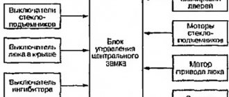
Sensors that record the wheel speed send this data to the control unit. The unit then processes the received information and controls the operation of the valve actuator unit, which is connected to the brake system. Using magnetic valves, the fluid pressure in the brake circuits is regulated.
In the process of reducing speed, the data is processed electronically, and the operation of the system is adjusted according to the development of the situation on the road and the quality of the road surface.
Modern cars are equipped with the most effective four-channel ABS systems. Here there are sensors near each wheel, and rotation adjustment can be carried out for each wheel separately. This is very convenient on difficult roads, when each wheel may have a different surface. Three-channel systems consist of three sensors, two of which are located on the front wheels and one on the rear pair.
The cheaper, simpler, but no less effective two-channel system operates on the basis of two sensors. One is installed near the front wheel, the second - near the rear wheel diagonally. The system works clearly and smoothly. Problems with it rarely happen, as owner reviews say.
ABS sensor repair
If a faulty ABS sensor is detected, it is dismantled, after which the issue of replacement or repair is decided. The cost of the device is quite high, and often there is a long wait for its delivery, which makes repairs quite feasible. The work is performed in the following order:
1. The sensor is disassembled by cutting off the part in which the measuring coil is located with a hacksaw. The body is carefully filed in a circle so as not to damage the fasteners.
2. The plastic casing protecting the coil is removed using a sharp knife and the winding is unwinded from the frame.
3. Wind a new coil with a wire of the same diameter. The RES-8 relay winding is suitable for this. The number of windings must provide the required resistance value - 0.92-1.22 kOhm. The work is carried out very carefully, since the wire is quite thin, and if it breaks, the process begins again.
4. The ends of the wires are soldered to the terminals, and the coil is effectively insulated from moisture using silicone or wax sealant.
5. The sensor is assembled by restoring the old housing. If the shell is critically damaged, it is made independently from the body of an electrolytic capacitor, suitable in size, and epoxy glue. A hole is made at the bottom of the body for the coil rod. After placing the updated part there, glue is poured.
6. After the glue has dried, the capacitor shell is removed, and the sensor mount is glued to its original place.
7. After the repair is completed, the sensor body is ground with sandpaper to accurately fit the socket. During the installation process, observe the following rules:
- The core of the device is placed parallel to the teeth of the response disk and is controlled so that it does not overlap a pair of adjacent teeth;
- A gap of 0.9-1.1 mm is left between the tooth and the core.
At the end of the installation, check the functionality of the system by starting the engine and making sure that the ABS indicator goes out 6 seconds after the start.
Operating principle of a passive ABS sensor
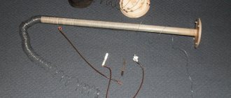
The passive sensor is a permanent magnet equipped with a core in a metal winding. Replacing an ABS sensor on a Chevrolet of this type is almost never carried out due to its simplicity and high reliability.
When a gear passes through a magnetic field, an alternating current is generated in the coil. The current strength depends on the wheel speed. It is this data that is analyzed by the ABS electronic control unit.
Sensors have advantages and disadvantages. Advantages include high reliability, resistance to dirt, no need for external power sources, ease of replacement of the ABS sensor, and resistance to wear. But the sensor begins to work effectively at speeds greater than five kilometers per hour. The accuracy of passive sensors is poor.
Design and operation of speed sensors based on the Hall element
Sensors based on Hall elements are the most common due to their simplicity and reliability of operation. They are based on the Hall effect - the occurrence of a transverse potential difference in a flat conductor placed in a magnetic field. Such a conductor is a square metal plate placed in a microcircuit (Hall integrated circuit), which also contains an evaluation electronic circuit that generates a digital signal. This chip is installed in the speed sensor.
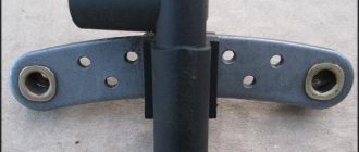
Structurally, a DSA with a Hall element is simple: it is based on a microcircuit, behind which there is a permanent magnet, and a metal plate-magnetic circuit can be located around it. All this is placed in a housing, in the back of which there is an electrical connector or conductor with a connector. The sensor is located opposite the pulse rotor, which can be made either in the form of a metal gear or a ring with magnetized sections; the pulse rotor is rigidly mounted on the wheel hub.
The operating principle of the Hall sensor is as follows. The Hall integrated circuit constantly generates a digital signal in the form of rectangular pulses of one frequency or another. At rest, this signal has a minimum frequency or is completely absent. When the car begins to move, magnetized areas or rotor teeth pass by the sensor, which entails a change in the current in the sensor - this change is monitored by an evaluation circuit that generates an output signal. The frequency of the pulse signal depends on the speed of rotation of the wheel, which is used by the anti-lock braking system.
DSAs of this type do not have the disadvantages of inductive sensors; they allow you to measure wheel speed literally from the first centimeters of vehicle movement; they are accurate and reliable in operation.
Active
Pulse rings with permanent magnets are used together with magnetoresistive sensors. The ring is fixed to the hub. The sensor is a semiconductor to which a constant voltage is applied. When the sensor passes through a magnetic field, the resistance across the semiconductor changes.
These sensors are the most accurate, but the design is also more complex, hence their fragility. Replacing the ABS sensor is associated with certain difficulties.
The best manufacturers
If you don’t know which company’s DSA is best to install on your car, then use the recommendations of specialists. Most often, they persuade drivers to use models from well-known brands. The latter value their reputation, so they supply only proven, high-quality devices to the domestic market.
Best manufacturers:
- StartVOLT (Russia);
- SAILING (China);
- BOSCH (Germany);
- ASAM (Romania);
- DELPHI (UK);
- Te Parts (Latvia);
- Nissan (Japan);
- Hyundai (South Korea);
- Febi (Germany).
Malfunctions
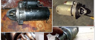
Sensors of the first design rarely break down - there is practically nothing in them that fails. Causes of malfunction include damaged wiring, unqualified repairs, and mechanical damage in the event of an accident. The elements cannot be repaired, and the problem can only be solved by replacing the ABS sensor. This is exactly what they do at Nissan.
Sensors can fail due to strong magnetic fields, but this problem can occur on special vehicles, but on city passenger cars it is excluded.
Incorrect operation may be due to play in the bearings on which the impulse rings are installed. The ring may also break. If the sensor fails, then most often experts recommend replacing the ABS wheel sensors.
Analysis of diagnostic results
The problem with the ABS function does not always lie in the sensors. The culprits of system failure may also be the wires connecting the elements to the control unit. That is why it is necessary to carry out 3 measurements and draw the following conclusions based on the results:
- If the resistance of the ABS sensor tends to zero or, conversely, the device shows an infinity symbol, then there is a malfunction of the element itself. Another option is a violation of the insulation or a break in the section of conductors from the connector to the sensor.
- The tester shows that the resistance is within normal limits, but when the brake disc rotates, its value remains constant. There are two versions here: severe contamination of the gear ring (as an option - destruction) and, again, failure of the sensor.
- The absence of voltage in the supply line indicates a break in the electrical circuit coming from the controller.
Need for replacement
Any system malfunction will definitely be diagnosed - ABS has built-in diagnostics. It is triggered before each engine start. If the system is working normally, this indicator will light up when the engine starts, and then go out after half a minute.
But if the controller does not work correctly, then when the engine is running, the indicator will be constantly on or will blink while driving. This is one of the first signs that one of the sensors is faulty.
In addition, if the sensor or sensors are faulty, the on-board computer may generate errors; during sharp braking, the wheels may lock, and there may be a characteristic vibration on the pedal when braking. When the handbrake is off, the parking brake light may come on.
If your car has at least one of the problems described, then you need to carry out a competent and complete diagnosis. If it is discovered that the sensor has failed, then it needs to be replaced with a new one.
However, before replacing the front ABS sensor, you can try checking the gaps between the sensor and the ring and the tire pressure. You can diagnose and visually check the entire electrical circuit. If no obvious faults are found, then the problem is in the sensors or electronic systems.
How to diagnose the ABS system
To obtain complete and reliable information about the state of the entire system, diagnostics should be carried out using special equipment. For this purpose, the manufacturer provides a special connector. After connection, the ignition is turned on and the test begins. The adapter issues error codes, each of which signals a breakdown of a specific component or element of the system.
A good model of such a device is Scan Tool Pro Black Edition from Korean manufacturers. The 32-bit chip makes it possible to diagnose not only the engine, but also all components and assemblies of the car. The cost of such a device is relatively low.
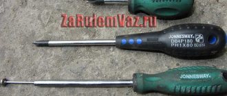
Diagnostics can also be carried out at service centers and service stations. However, even in garage conditions, if you have certain knowledge, identifying defects will not be difficult. To do this, you will need the following set of tools: soldering iron, tester, heat shrink and repair connectors.
The check is performed in the following sequence:
- the wheel being tested is jacked up;
- the control unit and controller outputs are dismantled;
- repair connectors are connected to the sensors;
- The resistance is measured with a multimeter.
A fully functional ABS sensor at rest has a resistance of 1 kOhm. When the wheel rotates, the readings should change; if this does not happen, the sensor is faulty. It should be remembered that different sensors have different meanings, so you need to study them before starting work.
Checking the ABS sensor with a multimeter
In addition to the device itself, you need to find a description of the sensor model. Further work is performed in the following sequence:
- The machine is placed on a flat, uniform surface, and its position is then recorded.
- The wheel is removed where the ABS sensor will be checked.
- The connector is disconnected and the contacts of both the sensor and the plug itself are cleaned.
- The wires and their connections are inspected for abrasions and other signs of damage to the insulation.
- The multimeter switch is switched to resistance measurement mode.
- The tester probes are applied to the output contacts of the sensor and readings are taken. Under normal conditions, the device display should show the number indicated in the sensor data sheet. If there is no such information, we take readings of 0.5 - 2 kOhm as the norm.
- Then, without removing the probes, the car wheel spins. If the sensor is working properly, the resistance will change, and the higher the rotation speed, the more the resistance changes.
- The multimeter is switched to voltage measurement mode and measurements are taken.
- At a wheel rotation speed of 1 revolution/sec. The indicator should be within 0.25 - 0.5 V. The higher the rotation speed, the greater the voltage.
- All sensors are checked in the same sequence.
In addition, the entire wiring harness is connected to each other to make sure there is no short circuit.
It should be remembered that the design and values of the sensors on the rear and front axles are different.
Based on the data obtained during measurements, the performance of the sensor is determined:
- the indicator is lower than normal - the sensor is unusable;
- a very low resistance value or near zero - short circuit of the coil turns;
- when bending the wiring harness, the resistance indicator changes - the wire strands are damaged;
- the resistance indicator tends to infinity - a break in the conductor or core in the induction coil.
You should know that if, during diagnostics, the resistance reading of one of the ABS sensors is very different from the others, it means it is faulty.
Before you start ringing the wires in the harness, you should find out the pinout of the control module plug. Then the connections between the sensors and the ECU are disconnected. And after that, you can start sequentially ringing the wires in the harness according to the pinout.
Checking the ABS sensor with an oscilloscope
An oscilloscope can also be used to determine the performance of ABS sensors. However, it is worth noting that this will require some experience in working with it. If you are one of the avid radio amateurs, then this will not seem difficult, but the average person may have a number of difficulties. And the main one is the cost of the device.
This device is more suitable for specialists and craftsmen of service centers and service stations. However, if you have such a device, it will be a good assistant and will help identify faults not only in the ABS system.
An oscilloscope is used to visualize the electrical signal. The amplitude and frequency of the current are displayed on a special screen, thanks to this you can obtain accurate information about the operation of a particular element.
So, the test begins using the same method as with a multimeter. Only at the multimeter connection point is an oscilloscope connected. And then the sequence is like this:
- the suspended wheel rotates at a frequency of approximately 2 - 3 revolutions per second;
- vibration readings are recorded on the instrument display.
After determining the integrity of one wheel, you should immediately begin checking on the opposite side of the axle. Afterwards, the data obtained is compared and conclusions are drawn based on them:
- provided that the readings are relatively identical, the sensors are in good working order;
- the absence of a step-like phenomenon when setting a smaller sinusoid signal indicates normal operation of the sensor;
- a stable amplitude with peak values not exceeding 0.5 V at the speeds mentioned above indicates the integrity of the sensor.
Checking without instruments
The performance of ABS sensors can also be checked by the presence of a magnetic field. To do this, take any iron object and apply it to the sensor body. When the ignition is turned on, it should be attracted.
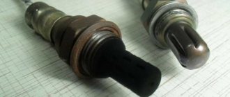
In addition, you should carefully inspect the sensor itself and its installation location for damage. The wire should not have any abrasions, chips, insulation damage, etc. The sensor connector must be free of traces of oxidation.
It is important to know that the presence of dirt and oxidation can distort the signal from the sensor.
Replacement instructions
Let's look at the process of replacing a Toyota ABS sensor on the rear axle. The car is placed on a level surface with the hand brake applied. To increase safety, chocks are placed under the wheels. At the same stage, you need to remove the negative terminal from the battery.
Next, the rear seats, threshold trim, and door seal are dismantled. You need to get to the connector. To do this, bend the clamps and pull off the trim near the shock absorber strut mount. Then disconnect the connector.
Next, the car is raised with a jack, and a block is placed under the bottom for safety. After this, you can unscrew and remove the wheel. The sensor is installed on a bracket. To replace the ABS sensor, you need to spray the bracket with liquid key and wait a little. Then unscrew the mounting bolt. By tapping the element, remove the sensor with a screwdriver.
Then you need to unscrew the fasteners holding the wire brackets. Two bolts on the arch, and one on the shock absorber strut. The wire should be pulled out into the interior.
Installation of the new device is carried out in the reverse order. This completes the operation. Sensors on other car models are changed using a similar scheme (replacing the Lancer ABS sensor is no exception).
Where can I buy
Popular models and new items can be purchased in specialized stores and showrooms that sell spare parts and accessories for motor vehicles. Managers will explain in detail and also give useful tips and recommendations - what types of sensors there are, which company is better to buy, how to choose, how much it costs.
If there is no opportunity to buy the necessary spare part at your place of residence, the best inexpensive models are always available to order online in the online store. This can be done easily through the Yandex.Market aggregator or leading online trading platforms that offer to select the desired product based on various parameters - VIN code, car make or model, etc. At the same time, there is always the opportunity to look at the description, study the characteristics, reviews and photos, and also consider the possibility of selecting analogues of the original parts.
How to check the abs block
An anti-lock brake system is an essential component of any modern car.
Not all domestic drivers are accustomed to this technical equipment. But some have already learned not only to take advantage of its benefits, but also to independently diagnose the operation of the system. The essence of ABC is that during emergency braking, the movement of all four wheels is prevented from blocking. This works to increase vehicle stability and reduce braking distance. It is especially important when driving on slippery surfaces - gravel, icy, wet asphalt. The car does not skid, the level of controllability remains high, although the brake pedal is pressed to the limit.
Key parts are a hydraulic unit that modulates fluid pressure, wheel speed sensors, their location, and a computer that processes information from the sensors and transmits it to the main unit. Location: under the hood, in the space between the brake cylinders.