What is a torpedo? In short, this is the dashboard. The word “torpedo” came to us from the West and has now become firmly established in the everyday life of domestic car enthusiasts.
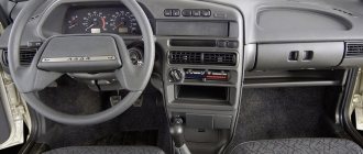
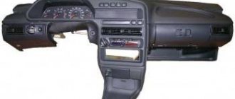
Dashboard of a VAZ 2115 car
The instrument panels on the VAZ 2113, 2114 and 2115 are almost the same. These are complex collapsible structures made of metal with plastic inserts. In addition, in the panels of this line of VAZ models, engineers actively used polymer film, which covers most of the controls.
Diagram of the main elements of the VAZ 2115 dashboard
Torpedo device
What is a torpedo? In short, this is the dashboard. The word “torpedo” came to us from the West and has now become firmly established in the everyday life of domestic car enthusiasts.
Dashboard of a VAZ 2115 car
The instrument panels on the VAZ 2113, 2114 and 2115 are almost the same. These are complex collapsible structures made of metal with plastic inserts. In addition, in the panels of this line of VAZ models, engineers actively used polymer film, which covered most of the controls.
Diagram of the main elements of the VAZ 2115 dashboard
Purpose
Let us immediately note that the task of this sensor includes several functions. It is intended:
- To supply an electronic signal to the speedometer installed on the dashboard, resulting in the ability to control the speed of movement and the distance traveled;
- Based on the readings of this sensor, the electronic unit adjusts and sets optimal speed in different modes of movement;
- The sensor signals influence the operation of the idle speed sensor.
How to remove the instrument panel from a VAZ 2115
Since the instrument panels on the thirteenth, fourteenth and fifteenth models are the same, the procedure for dismantling the dashboard will be considered using the example of the VAZ 2115. But before you begin, you should stock up on everything you need.
Tools and materials
- flat blade screwdriver;
- Phillips screwdriver;
- pliers;
- set of open-end wrenches.
Sequence of operations when removing the dashboard from a VAZ 2115
- Using a Phillips screwdriver, remove the screws that hold the left side of the console.
The left side of the VAZ 2115 console is removed with a Phillips screwdriver
The right side of the VAZ 2115 console is attached to 5 screws
The VAZ 2115 heater handles are removed manually
Just pull the handle of the VAZ 2115 fan towards you
Self-tapping screws from the VAZ 2115 panel brackets are unscrewed with a Phillips screwdriver
Self-tapping screws from under the instrument window of the VAZ 2115 are removed with a Phillips screwdriver
The self-tapping screw plug on the VAZ 2115 dashboard is pryed off with a flat screwdriver and removed
All instrument wires of the VAZ 2115 are disconnected manually
The nuts on the steering brackets of the VAZ 2115 are unscrewed with an open-end wrench
The nut on the VAZ 2115 panel bracket is unscrewed with an open-end wrench
The last screw holding the VAZ 2115 dashboard is located at the driver's door
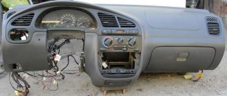
Torpedo VAZ 2115 is removed
Video: removing the dashboard from the tag
Is it allowed to install a dashboard on a VAZ 2115 from another car?
In short, no. The dashboard on the VAZ 2115, 2114 and 2113 has a number of design features that are not found on other cars. Its cross members, mounting brackets and console sides are too long. There is nothing like this even on other VAZ models, not to mention foreign cars. But it should be noted that car owners often practice reverse replacement. In particular, a dashboard from a VAZ 2114 can be successfully installed on a VAZ 2109. But in this case, you have to trim the sides of the console and drill new mounting holes on the brackets.
How to check the speedometer sensor with your own hands
To check the status of the speedometer sensor, you need to do the following:
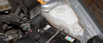
- Open the hood of the VAZ-2114.
- Get rid of the adsorber, it will be more comfortable to work.
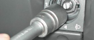
- Determine where the wire to the sensor is located in the CV joint area.
- Locate the tool located under the throttle assembly.
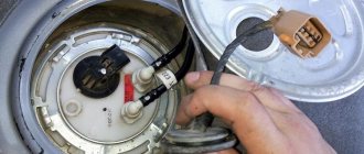
Finally, you get to the sensor itself. Take a look at what it looks like and check the functionality of the device. What is it?
- Look at the stem, it is made of plastic, this material often breaks and deteriorates.
- Failures also occur with the plastic rod.
- Pay attention to the plastic drive gear - ideally all the teeth should be in place. If they are cut off, then the sensor’s performance leaves much to be desired.
That is why, even at the stage of absence of breakdowns, service station specialists recommend replacing plastic parts with metal ones.
If the rod and gears are made of metal, the speedometer is unlikely to break soon. When changing the mechanism, consider the following features:
- The VAZ-2114 can be equipped with units with different volumes.
- The gears are not the same color. The numerical values of the speedometer drive change in accordance with the different gear ratios of the main combination of pairs. This means that the shade of the gears must match and remain the same.
Important points regarding replacement
- When removing the right side of the console, be careful. Behind it are wires that can easily get caught on the side and be damaged. So before removing this cover, you should remove the negative terminal from the battery. You should also turn off the car radio by removing its connector from the common wiring harness located behind the upper instrument panel;
- Removing the plastic handles from the stove levers can cause serious difficulties. The fact is that there are protrusions on the stove levers (top and bottom), and holes on the handles. When you put the handle on, it snaps onto the lever. The only way to remove it is to pry it off with a flat screwdriver as shown in the picture. But when prying up the handle with a screwdriver, you should not bend it too much: the plastic breaks very easily;
The handles on the levers of the VAZ 2115 stove can be removed using a flat screwdriver
So, a novice car enthusiast is quite capable of removing the dashboard from a VAZ 2115 and other cars in this line. All that is required is patience and attentiveness. If, after unscrewing all the fasteners, the dashboard stubbornly refuses to come off, you should inspect everything again: it is quite possible that some tiny screw was missed.
Functions
It is incorrect to assume that the DS serves solely to transmit information regarding the current speed of the vehicle. In fact, this device has several tasks.
- Transferring information to the dashboard, namely the speedometer, about the speed of the car.
- Supports optimal functioning of the idle air control.
- Transferring data to the electronic control unit in order to maintain optimal speed depending on the travel mode.
The DS is connected to the speedometer and controller using a mounting block located in the engine compartment. And inside the car, directly on the heater fan relay, there is a sensor fuse.
Errors and symptoms
If the device starts to work incorrectly or breaks down, you should pay attention to the on-board computer screen. Diagnostics of errors will determine that the DS has stopped functioning properly and measures should be taken to eliminate the breakdown
Error code
What does it mean
This error indicates that the computer does not receive a signal from the speed sensor.
This error code informs about the receipt of an unstable signal from the DS, which is intermittent.
If these error codes appear on the dashboard, you should definitely inspect the electrical circuit for oxidation or damage to the integrity of the contacts. Often it is because of this that the DS stops transmitting information.
But there are other signs by which you can determine that the DS is out of order:
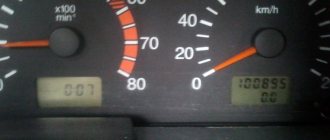
- On the dashboard, the speedometer shows incorrect speed data or the needle does not move at all;
- With a slight acceleration, the speed floats, the engine switches off on its own;
- Fuel consumption increases;
- Engine power is noticeably reduced.
These signs may be signals of problems with other systems. But if you find one of the characteristic signs of a DS failure, plus one of two error codes appears on the on-board computer, then the problem lies precisely in the speed sensor.
Functionality check
The check is performed in several ways. Decide for yourself which one you prefer.
Checking the operation of the DS
Before doing this, be sure to check the condition of the wiring and contacts. If they are oxidized or rusted, or there are breaks in the circuit, then the DS itself may well be operational. You just need to return the wiring and contacts to a functional state. If the check shows that everything is intact and there are no problems with the contacts, then diagnose the speed sensor.
- If you don’t want to remove the DS, then place the car on a level surface, secure it with blocks and lift the left front wheel with a jack. Connect the voltmeter to the contacts of the sensor and begin to rotate the wheel with your hands. At the same time, look at the voltmeter data. If the voltage increases with frequency in proportion to the increase in wheel speed, the DS operates normally.
- Another method also does not require removing the measuring device. But for this you will need a test lamp. Use a jack to lift the left front wheel and connect the test lamp to the DC contacts. After this, manually rotate the wheel. If the lamp lights up, the sensor is working well.
- The third method involves dismantling the sensor and then checking the input and output voltage. The device for measuring the indicators will be a voltmeter.
- The fourth method is actively used by those who prefer to repair their car with their own hands. Here you have to check the sensor drive. To do this, lift the wheel using a jack and remove the sensor. Feel for the DS drive, and then begin to rotate the wheel. You can feel with your fingers that the drive rotates. If there are no jams, everything rotates evenly, then the drive is in good condition.
Withdrawal procedure
- Remove the negative cable from the battery.
- Unscrew the left trim of the instrument panel console.
- Remove the cover. To do this, you need to remove the lower protrusion from the bracket.
- Unscrew the right panel of the instrument panel console.
- Disconnect the wires from the cigarette lighter.
- Disconnect the wires from the cigarette lighter light bulb.
- We push from the inside and take out a niche for small items.
- Unscrew the 2 screws and push the diagnostic connector block inside.
- Remove the heater fan switch handle.
- Using a narrow screwdriver, remove the handle from the lever.
- Unscrew the 2 screws above the instrument panel.
- Unscrew the two screws under the instrument panel.
- Remove the plug and unscrew the screw of the upper fastening of the lining.
- Unscrew the 2 screws of the lower fastening of the lining.
- We move the cover to the side.
- Mark the order in which the blocks are connected to the switches.
- Disconnect the wires from the switches.
- Remove the instrument panel.
- Unscrew the bolts securing the steering column and lower it down.
- Unscrew the 2 screws securing the panel to the bracket.
- Unscrew the 2 screws securing the bracket to the right cross member.
- Unscrew the 2 screws of the lower bracket fastening.
- We move the bracket to the side.
- Unscrew and remove the light guide from the instrument panel.
- We unscrew the 4 screws securing the stove control unit and recess it inside.
- Remove the lamp socket for the heater fan switch handle.
- Press the right lock and remove the air duct from the panel.
- Pull out and remove the headlight hydraulic adjustment handle.
- Remove the instrument lighting control knob
- Remove the decorative insert of the instrument panel.
- Unscrew the light guide.
- Unscrew the nut securing the hydraulic corrector and recess it inside the panel.
- Unscrew the nut securing the instrument lighting control.
- We take out the hydraulic corrector illumination lamp.
- Disconnect the wires from the instrument lighting control.
- Disconnect the wires from the immobilizer sensor.
- Disconnect the wires from the immobilizer unit.
- Disconnect the wires from the glove compartment light bulb.
- Disconnect the wires from the socket of the portable lamp.
- Unscrew the 2 screws of the top panel fastening
- Unscrew the 2 screws on the bottom fastening of the panel.
- Unscrew the self-tapping screw securing the panel to the left cross member.
- Remove the instrument panel.
- Installation of the instrument panel on the VAZ 2114 is carried out in the reverse order.
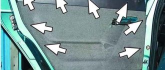
Video about removing the panel from a VAZ 2114 engine soundproofing panel:
Similar on the site:
0 Comments
6 Pingbacks
- How to remove and install the heater radiator on a VAZ 2114 | Repair 2114
- What to do if the heater fan does not work on a VAZ 2114 | Repair 2114
- How to remove and install the heater on a VAZ 2114 | Repair 2114
- How to remove and install the electronic control unit of a VAZ 2114 - Repair 2114
- How to remove and install a heater on a VAZ 2114
- How to remove and install the electronic control unit of a VAZ 2114
Leave a Reply Cancel reply
Categories
Similar articles
How to remove and install the headlight unit on a VAZ 2113, 14, 15.
How to remove and install the front turn signal on a VAZ 13, 14, 15.
How to remove and install the brake light switch on a VAZ 13, 14, 15
How to remove and install the reverse light switch.
Replacing switches on the instrument panel of a VAZ 13-15.
What's next
After all devices are disconnected from the car, you need to remove the handles from the heater switches.
This can be difficult to do, because they are fixed quite firmly. To install the handles, special latches are used, which are installed inside. There is a small protrusion on each handle that will help us remove them. You just need to get into this hole with the tip of a minus screwdriver, then pick up the latch and lift it up. The further procedure is as follows:
- The handle of the stove motor is removed. It is enough just to slightly pull it towards you;
- The torpedo is fastened to the instrument block using several self-tapping screws. They are removed using a “plus” screwdriver;
- Next, you need to remove the plug. It is fixed with a single self-tapping screw that needs to be removed;
- The cover is held in place by two fasteners. And again the screwdriver comes to our aid;
- Let's move on to the cables that are connected to the switches. They must be carefully removed, having previously marked each of them;
- Next, remove the steering mount bracket bolts;
- remove the fasteners from the bottom of the bracket. The key to 8 will help us here;
- remove the light guide;
- Next in line is the heating system control unit. Unscrew the fasteners and remove the cartridges;
- in front of us is a decorative insert. We also don’t need it, so we temporarily get rid of it;
- remove the hydraulic corrector;
- The last step is to dismantle the upper and lower fasteners.
That's all, actually. Now the torpedo is carefully removed, and you can perform any necessary actions with it. Assembly is carried out in reverse order. The procedure is quite complex and troublesome, filled with various little things, so please spare yourself time and patience. If any points remain unclear to you, you can watch the video on our website.
There is a special offer on our website. You can get a free consultation with our corporate lawyer by simply submitting your question in the form below.
Removing (European) instrument panel 2113-2115
Using a Phillips screwdriver, unscrew the three screws securing the left screen of the center console: lower, middle and upper.
Remove the left screen of the center console.
Also, use a Phillips screwdriver to unscrew the five screws securing the right screen of the center console and remove the screen.
Disconnect the negative cable terminal from the battery. We remove the radio receiver and disconnect the block of its wiring harness (if the radio receiver is installed) or remove the plug container the instrument panel Disconnect the wiring harness connector from the cigarette lighter and remove the ashtray backlight lamp socket
Using a screwdriver, remove the handles from the heater damper control levers.
For clarity, we show these operations on a removed block of heater control levers. We insert the blade of a screwdriver between the handle and the lever on the side opposite to the protrusion on the handle.
There is a hole in the plastic of the handle into which the lever antenna fits.
Remove the handle from the heater fan switch.
Use a Phillips screwdriver to unscrew:
a self-tapping screw securing the instrument panel to the bracket on the left and similarly - on the right there are two self-tapping screws located above...