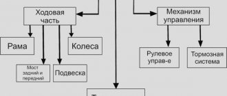
05/07/2021 1 413 Ignition system
Author: Ivan Baranov
The coil is considered the main part of the ignition system; if it is inoperative, starting the car engine is impossible. This is due to the fact that the operating principle of the ignition coil allows the spark to appear, which is necessary to start the power unit.
[Hide]
Purpose of the ignition coil in a car
Such a device is designed to accumulate energy and generate voltage. It is required for the discharge to appear on the spark plug electrode. The presence of a spark contributes to the efficient starting of the power unit. The main option of the device is based on the law of induction. The current supplied by the battery stops supplying the device at the desired moment of ignition.
Design features of short circuit
The short circuit for the machine is arranged as follows:
- Insulating element. Used as an insulating part.
- Device body. It contains the remaining components of the short circuit. Usually made of metal, but can be made of high-strength plastic.
- Insulation paper.
- Primary winding. Regardless of the type of system, this part consists of the main conductor. The cable must be insulated. Depending on the short circuit model, it can have from 100 to 150 turns. The primary winding is equipped with outputs, each of which is rated at 12 volts.
- Secondary winding. Its installation is usually carried out outside the device, and the number of turns in the part can range from 15 to 30 thousand. Similar mechanisms are installed in ignition modules, two-terminal, as well as dual coils; their presence may include individual systems. A voltage of about 35 thousand volts is formed inside the secondary element, which is subsequently supplied to the spark plugs. For high-quality insulation of contact elements in short circuits, lugs are used.
- Terminal contact of the primary part. It can be designated on the short circuit by the symbol K.
- Contact bolt. Used to fix the device and transfer the contact.
- The central output through which high-voltage voltage is transmitted. It is served on candles.
- Protective cover of the device.
- Terminal power supply. Designed to connect the coil to the on-board network.
- Device contact spring.
- Brace.
- External cable for connecting the device.
- Core. The design of the element prevents the formation of eddy currents.
Design diagram of a short circuit device in a car
Location of the ignition coil in a car
To find out where the short circuit is located in a particular vehicle, we recommend that you refer to the service manual. Typically the device is located in the engine compartment. It can be seen on the fender or on the dividing partition that separates the car interior from the engine compartment. In some cases, the device may be located directly on the power unit.
How can you check the serviceability of the ignition coil?
Despite the fact that the design of the reel is, at first glance, simple, it is still possible for the ignition coil to malfunction. The symptoms of the defects are similar. The engine begins to operate unstably, “triple”, and failures occur. The engine may simply not start. On new cars, a malfunction will be indicated by the “CHECK ENGINE” light.
Previously, the coil was often checked in the old “old-fashioned” way. While cranking the engine, check for the presence of a spark between the spark plugs and the ground of the car. In modern engines, such experiments can lead to dire consequences. You can damage not only the ignition coil, but also other complex electronics of the car. Let's look at the most common ignition coil malfunctions, symptoms and methods for diagnosing them. For example, the ignition coil gets hot. In principle, the coil should heat up, but not excessively. With prolonged use, whether we like it or not, the insulation “aging” occurs. And this process is not limited to bobbins. As a result of the deterioration of the insulating properties of the dielectrics in the coil, the risk of an internal short circuit and, as a result, overheating increases. If the temperature rises above 150 degrees, then most likely the coil needs to be replaced.
Operating principle of the ignition coil
In general, the operating principle of the ignition coil can be divided into four stages:
- The current is supplied to the primary device of the transformer unit and forms a magnetic field in it.
- As a result of the current interruption, the field generates a high voltage current on the secondary device.
- From the secondary component, voltage is supplied to the main terminal of the assembly.
- From the terminal element, voltage is supplied to the distribution unit. From there it is supplied to the spark plugs, where a spark discharge occurs.
Automotive short circuit operates on the principle of a transformer device. First, the secondary winding is wound, it is equipped with a thin conductor, and then the primary winding. The number of turns of the latter is smaller, but the conductor is much thicker. When the contact parts are connected, the magnitude of the primary current increases to its greatest value. It is determined by the battery voltage parameter, as well as the value of the ohmic resistance of the primary device.
The current increasing in the system encounters self-induction resistance, which is directed counter to the battery voltage. When the contact elements are closed, a current passes through the primary device and creates a magnetic field that also crosses the secondary winding. As a result, a high voltage current is generated in the latter. At the moment when the contact elements of the interrupting device open, a self-inductive emf appears in both windings. The higher the secondary voltage, the faster the magnetic flux generated by the primary device disappears.
A primary current can be supplied to the ferromagnetic core, which helps reduce the energy that collects in the magnetic field. To reduce saturation, an open-circuit magnetic circuit can be added to the design. This makes it possible to create a short circuit in which the inductance value of the primary device will be up to 10 mH, and the primary current parameter will be 3-4 amperes. It is not allowed to use a higher current value, as this will lead to burning of the contact elements of the interrupter device.
The principle of operation of the ignition coil in a car is presented in detail in the video of the NGKNTK EMEA channel.
As a result of an increase in current in the secondary section of the electrical circuit, the voltage drops sharply to the so-called arc voltage. The last value remains unchanged until the energy reserve drops to the minimum parameter. On average, battery ignition duration in cars is about 1.4 ms. As a rule, this is enough to ignite the flammable mixture. When the arc voltage is removed from the system, the residual energy is used to support the damped current and voltage fluctuations.
The duration of the arc charge depends on:
- stored energy values;
- ratio of fuel and air in the combustible mixture;
- the frequency at which the engine crankshaft rotates;
- compression ratio, etc.
If the rotation speed of the internal combustion engine crankshaft increases, then the time at which the contact elements of the interrupter device remain closed decreases. And the primary current does not have time to increase to its maximum value during this period. This leads to a decrease in the energy reserve that is collected in the short-circuit magnetic system, as a result of which the secondary voltage value drops.
Negative characteristics of systems that use mechanical contact elements appear at too low or high engine speeds. If the rotation speed is low, then an arc charge appears between the contact components of the interrupter assembly, which takes away some of the energy. If the speed is too high, the secondary voltage parameter drops, which is associated with vibration of the contacts of the interrupter assembly. Depending on the type, the short circuit may be equipped with an additional resistor element; such devices operate on a different principle.
The Soldering channel talked in detail about checking such a short-circuit characteristic as resistance using a multimeter.
During the starting mode, when the voltage from the battery decreases, the resistor device closes through additional contacts located on the traction relay. For this purpose, contact elements of an additional starter activation relay can be used. This allows the primary mechanism to produce a voltage of 7-8 volts. During the operating mode of the power unit, the voltage parameter required to power the electrical equipment is 12-14 volts.
Nickel or constant wire is usually used to wind an additional resistor device. If the first option is used, then the resistance is considered variable, since it changes in accordance with the amount of current passing. When the internal combustion engine operates at high speeds, the primary current decreases and the resistance parameter drops.
Features of choosing motorcycle ignition coils
Not only automobile internal combustion engines are equipped with step-up transformers for spark generation; they are present in:
- boat motors;
- mopeds and motorcycles;
- lawnmowers;
- chainsaws;
- electric generators.
If you are selecting an ignition coil for a Verkhovina moped, usually a B-300 was installed in it, then please note that the device with the similar name B-300B has a smaller number of turns in the field winding. Therefore, replacing the B-300 with the B-300B is impossible. Usually the engine doesn't even start. But if the B-300 is replaced with a similar device from the IZH motorcycle, the motor will work perfectly.
B-300
Soviet motor scooters such as “Ant” and “Tourist” used B-51 reels. It differs from automotive devices in that not 12, but 6 volts are supplied to the primary winding. The design of the B-51 is no different from other motorcycle reels. Many owners of scooters with B-51 coils replace them with 12-volt car ones. The transformation coefficient is enough to produce a high-quality spark, no worse than from the B-51.
Requirements for modern ignition coils
Requirements that apply to all modern short circuits:
- Simplicity of design. The simpler the short circuit is, the easier it is to install and maintain in the future. With a simpler device, the consumer will be able to independently diagnose in case of problems.
- Small dimensions and weight.
- High service life. The reliability of the device will ensure a long service life.
- Reliable protection against humidity and elevated temperatures. It is important that the design of the reel, as well as the materials used for its production, are resistant to elevated temperatures and moisture. This will ensure effective operation of the short circuit when weather conditions change and exposure to the aggressive environment characteristic of the engine compartment. The vapors that come from fuel and engine fluid should not harm the device or its body. If the structure body is damaged, this will lead to a deterioration in the functioning of the short circuit as a whole.
- Precision fit of the device, as well as resistance to short circuits. The design of the short circuit must be made so that its dimensions are sufficient to remove heat and ensure temperature stability.
Technical characteristics of ignition coils
The main characteristics of the devices are shown in the table.
| Characteristic | Description |
| Inductance | This parameter determines the ability of the short circuit to accumulate electricity and is measured in Gn. The energy collected inside the primary element of the device is proportional to the inductance value. The higher the inductance value, the more energy the mechanism can accumulate |
| Transformation parameter | Determines how much a short circuit can increase the magnitude of the primary voltage. The primary element receives 12-volt voltage from the battery, and when the circuit is opened, the current will drop from 6-20 amperes to 0. As a result of the current change, voltage appears on the primary component, and the transformation parameter determines how much this value has increased. This value is determined by the ratio of the number of turns in the secondary and primary devices |
| Short circuit resistance value | The primary coil device has a resistance of about 0.25-0.55 Ohms, and the secondary - from 2 to 25 kOhms. The magnitude of the spark formation power, as well as its energy, is inversely proportional to the resistance parameter in the primary component. The higher this value, the lower the amount of energy and power that is generated when a spark is applied. |
| spark energy | This parameter is about 0.1 joule and is consumed over 1.2 ms. In the spark plug itself, energy appears as a result of the formation of an arc charge when a breakdown occurs between the electrode elements. The voltage value on the parts is determined by the diameter of the spark plug, as well as the gap between the electrode components and the material from which it is made. This value is also affected by the temperature and pressure in the combustion chambers of the internal combustion engine, and the composition of the combustible mixture. For efficient operation of spark plugs, the voltage generated in the short circuit will be one and a half times greater than the voltage required to ensure breakdown |
| Breakdown voltage parameter | The breakdown itself is formed between the electrode components of the spark plug if the voltage across them and the breakdown correspond to each other. The operating parameter is determined by the gap between the electrodes, the pressure parameter in the combustion chambers, as well as the temperature of the combustible composition. When starting the internal combustion engine cold, this value should be greater, this will allow breakdown and the appearance of a spark discharge. This is important because the fuel and air in the engine are still cold. |
| Number of sparks appearing per minute | To calculate the number of sparks in one minute, you need to know the crankshaft speed, as well as the number of cylinders in the internal combustion engine. The spark value can be calculated by dividing the number of revolutions multiplied by the number of cylinders. And divide the resulting indicator by the number of engine cycles |
Types of car ignition coils
There are several types of short circuits used in cars. Each type has its own design and features.
Common ignition coil
This type of device is used in systems with or without a switchgear. This type of coil is the simplest in design and the most common.
Previously, common ignition coils were universally installed on all cars.
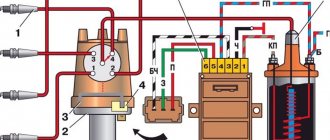
Common ignition coil diagram
Connection diagram for general automotive short circuit
Common Coil Features
Features characteristic of the general type of devices:
- The maximum value of the operating secondary voltage varies in the range from 18 to 20 kV.
- The core of the device is made of plates made of electrical steel. The thickness of each of them is from 0.35 to 0.5 mm. All plates are insulated relative to each other; varnish or scale is used as an insulating layer.
- An insulating tube is mounted on the core of the device, on top of which a secondary element is installed.
- The device body is made of sheet steel or aluminum. Inside it there is a magnetic circuit along the wall. The latter is made in the form of a roll of a wide strip of electrical steel.
- The speed at which the secondary voltage increases in a common short circuit ranges from 200 to 250 V/µs.
- The total duration of the phases during which a spark discharge occurs is up to one and a half seconds.
- The operating energy value at which a spark discharge occurs is from 15 to 20 mJ.
Custom ignition coil
The individual type of devices appeared later. Such coils are used in electronic ignition systems and are considered more reliable.
Individual ignition coil circuit
Scheme of design and connection of individual short circuit
Features of a custom coil
Features characteristic of individual-type devices:
- Such short circuits are also equipped with two windings - primary and secondary. But in them the primary element is installed inside the secondary.
- One core is mounted inside the primary device, and the second around the secondary.
- The short circuit itself is mounted on the spark plug. Thanks to this, the high-voltage signal is transmitted without loss of energy.
- Custom-type devices may include electronic elements of the ignition mechanism.
- The high-voltage signal, which is generated in the secondary device, is supplied directly to the spark plug. The transmission is carried out thanks to the presence of a tip, which consists of a spring element, a high-voltage rod, and an insulating layer.
- The main feature of this type of short circuit is the presence of a diode. It is used to quickly cut off high-voltage current on a secondary device.
Dual ignition coil
The dual version of the short circuit is an improved version of the general type of device. Used in many electronic ignition systems.
Dual ignition coil circuit
Double-type short-circuit device diagram
Dual Coil Features
Features characteristic of dual type devices:
- This type of equipment is equipped with two high-voltage contacts. Each of them is designed to produce a spark synchronously on spark plugs mounted on two cylinders. Moreover, only one of them will be located at the end of the compression stroke. On the second cylinder the spark will be idle.
- Connection to spark plugs can be done using two methods. Either through high-voltage cables, or one of them is connected directly using a tip, and the second - using a cable.
- By design, dual devices are installed in one block of two pieces. Then the short circuit will be considered four-terminal.
- The design of the device may not use a distribution unit, but then the spark will be supplied to two cylinders of the internal combustion engine.
Recommendations for operating ignition coils
The service life of ignition coils primarily depends on their correct use.
Therefore, the car owner needs to know about the maintenance and nuances of operating the devices. Of course, cheap and low-quality short circuits cannot boast of a long service life.
Reel Maintenance Rules
Device maintenance rules:
- You cannot leave the car for a long time with the ignition activated if the power unit is not started. When the ignition is turned on, not only does the battery discharge faster, but the service life of the short circuit also decreases.
- The reel needs maintenance periodically. The device must be cleaned of dust and dirt. Diagnostics of the quality of fixation of high-voltage cables is required. They must be securely fixed both on the candles and on the coil itself. When checking, you must make sure that no water gets into the device body or inside, otherwise the short circuit may quickly fail.
- It is not allowed to disconnect the “high voltage” from the device with bare hands when performing system maintenance. This cannot be done with the ignition activated.
- Problems with the operation of the short circuit can be identified through visual diagnostics or by checking the device for the presence of a spark. A visual inspection will allow you to identify cracks and other defects on the device body. Problems in the operation of the short circuit will be indicated by electrical burns, which are located on the cover next to the “high voltage” connector.
Short circuit faults
Problems that may occur during prolonged use or improper use:
- With prolonged use, there is a possibility of a short circuit in the windings of the device. If this happens, the transformer unit will overheat and will not be able to perform its functions.
- Prolonged use of short circuit at temperatures above 150 degrees will cause failure of the device.
- Damage to the device can occur if the battery does not operate correctly. If the battery is unable to supply the required voltage, the coil will not function properly. It is important that the battery can produce at least 11.5 volts of voltage.
- Malfunctions in the operation of the device can be caused by damage to the high-voltage cable.
- Damage to the insulating layer inside the mechanism will result in the device being unable to generate the required voltage. Such problems usually occur as a result of liquid or lubricant entering through a damaged seal. This leads to an increase in the resistance value.
- Individual coils are especially sensitive to the increased vibrations generated by the cylinder head. This leads to rapid breakdown of devices.
It's about the bobbin: how the ignition coil is designed and how it works
Oil filled reel
For more than half a century of the evolution of carburetor gasoline engines with a contact ignition system, the coil (or, as drivers of past years often called it, “reel”) has practically not changed its design and appearance, representing a high-voltage transformer in a sealed metal cup filled with transformer oil to improve the insulation between the turns windings and cooling.
An integral partner of the coil was a distributor - a mechanical low-voltage switch and a high-voltage distributor. A spark had to appear in the corresponding cylinders at the end of the compression stroke of the air-fuel mixture - strictly at a certain moment. The distributor carried out the generation of the spark, its synchronization with the engine cycles, and its distribution among the spark plugs.
The classic oil-filled ignition coil - "bobbin" (which means "coil" in French) - was extremely reliable. It was protected from mechanical influences by the steel shell of the housing, and from overheating by effective heat removal through the oil filling the glass. However, according to the poorly censored poem in the original version, “It wasn’t the bobbin – the idiot was sitting in the cab...”, it turns out that the reliable bobbin did sometimes fail, even if the driver is not such an idiot...
If you look at the diagram of the contact ignition system, you will find that the stopped engine could stop in any position of the crankshaft, both with the contacts of the low voltage breaker in the distributor closed and with the contacts open. If, during the previous shutdown, the engine stopped in the crankshaft position in which the distributor cam closed the contacts of the breaker supplying low voltage to the primary winding of the ignition coil, then when the driver for some reason turned on the ignition without starting the engine and left the key in this position for a long time, the primary winding of the coil could overheat and burn out... Because a direct current of 8-10 amperes began to pass through it instead of an intermittent pulse.
Articles / Practice Automotive relays: how they are designed, how to select and check them Cars are becoming smarter from year to year - they independently rotate the steering wheel, change the stiffness of the suspension, give the driver a massage of the butt and much more... However, the final executive... 101676 7 24 02.02. 2017
Officially, the coil of the classic oil-filled type cannot be repaired: after the winding burned out, it was sent for scrap. However, once upon a time, electricians at car depots managed to repair bobbins - they flared the body, drained the oil, rewound the windings and reassembled them... Yes, there were times!
And only after the mass introduction of contactless ignition, in which the distributor contacts were replaced by electronic switches, the problem of coil combustion almost disappeared. Most switches provided for automatic shutdown of the current through the ignition coil when the ignition was on but the engine was not running. In other words, after turning on the ignition, a short time interval began counting, and if the driver did not start the engine during this time, the switch automatically turned off, protecting both the coil and itself from overheating.
Dry coils
The next stage in the development of the classic ignition coil was the abandonment of the oil-filled housing. “Wet” coils were replaced by “dry” ones. Structurally, it was almost the same reel, but without a metal body and oil, coated on top with a layer of epoxy compound to protect it from dust and moisture. It worked in conjunction with the same distributor, and often on sale you could find both old “wet” coils and new “dry” ones for the same car model. They were completely interchangeable, even the “ears” of the mounts matched.
For the average car owner, there were essentially no advantages or disadvantages in changing technology from “wet” to “dry”. If the latter, of course, was made with high quality. Only manufacturers received the “profit”, since making a “dry” coil was somewhat simpler and cheaper. However, if the “dry” coils of foreign car manufacturers were initially thought out and manufactured quite carefully and served almost as long as the “wet” ones, Soviet and Russian “dry” bobbins gained notoriety because they had a lot of quality problems and failed quite often without any reason.
One way or another, today “wet” ignition coils have completely given way to “dry” ones, and the quality of the latter, even when produced domestically, is practically beyond criticism.
There were also hybrid coils: a regular “dry” coil and a regular contactless ignition switch were sometimes combined into a single module. Such designs were found, for example, on mono-injection Fords, Audis and a number of others. On the one hand, it looked somewhat technologically advanced, on the other hand, reliability decreased and the price increased. After all, two fairly heated units were combined into one, whereas separately they were cooled better, and if one or the other failed, replacement was cheaper...
Articles / Practice Overheating of the fuel pump: is it dangerous to drive “with a light bulb”? Does driving a car with a low fuel level in the tank cause the submersible fuel pump to overheat and fail? Popular rumor assures that yes... Professionals often say the same thing... 08/18/2017
Oh yes, to add to the collection of specific hybrids: on old Toyotas there was often a version of a coil integrated directly into the distributor distributor! It was, of course, not tightly integrated, and if the “bobbin” failed, it could be easily removed and purchased separately.
Ignition module - dispenser failure
A noticeable evolution in the reel world occurred during the development of injection engines. The first injectors included a “partial distributor” - the low-voltage circuit of the coil was already switched by the electronic engine control unit, but the spark was still distributed through the cylinders by a classic runner distributor driven by the camshaft. It became possible to completely abandon this mechanical unit by using a combined coil, in the common body of which individual coils were hidden in an amount corresponding to the number of cylinders. Such units began to be called “ignition modules.”
The electronic engine control unit (ECU) contained 4 transistor switches, which alternately supplied 12 volts to the primary windings of all four coils of the ignition module, and they, in turn, sent a high-voltage spark pulse to each of its spark plugs. Simplified versions of combined coils are even more common, more technologically advanced and cheaper to produce. In them, in one housing of the ignition module of a four-cylinder engine, not four coils are placed, but two, but they nevertheless work for four spark plugs. In this scheme, the spark is supplied to the spark plugs in pairs - that is, to one spark plug of the pair it arrives at the moment necessary to ignite the mixture, and to the other spark is idle, at the moment the exhaust gases are released from this cylinder.
The next stage in the development of combined coils was the transfer of electronic switches (transistors) from the engine control unit to the ignition module housing. Removing powerful transistors that heat up during operation “in the wild” improved the temperature regime of the ECU, and if any electronic switch switch failed, it was enough to replace the coil, rather than changing or soldering a complex and expensive control unit. In which individual immobilizer passwords and similar information are often written down for each car.
Each cylinder has a coil!
Another ignition solution typical of modern gasoline cars, which exists in parallel with modular coils, is individual coils for each cylinder, which are installed in the spark plug well and contact the spark plug directly, without a high-voltage wire.
The first “personal coils” were just coils, but then switching electronics moved into them - just as happened with ignition modules. One of the advantages of this form factor is the elimination of high-voltage wires, as well as the ability to replace only one coil, and not the whole module, if it fails.
True, it is worth saying that in this format (coils without high-voltage wires, mounted on a spark plug) there are also coils in the form of a single block, united by a common base. Such people, for example, like to use GM and PSA. This is a truly terrible technical solution: the coils seem to be separate, but if one “reel” fails, you have to replace the entire large and very expensive unit...
What have we come to?
The classic oil-filled bobbin was one of the most reliable and indestructible components in carburetor and early injection cars. Its sudden failure was considered rare. True, its reliability, unfortunately, was “compensated” by its integral partner - the distributor, and later - the electronic switch (the latter, however, applied only to domestic products). The “dry” coils that replaced the “oil” ones were comparable in reliability, but they still failed somewhat more often for no apparent reason.
Injection evolution forced us to get rid of the distributor. This is how various designs appeared that did not require a mechanical high-voltage distributor - modules and individual coils according to the number of cylinders. The reliability of such structures has further decreased due to the complication and miniaturization of their “offal”, as well as the extremely difficult conditions of their operation. After several years of operation with constant heating from the engine on which the coils were mounted, cracks formed in the protective layer of the compound, through which moisture and oil entered the high-voltage winding, causing breakdowns inside the windings and misfires. For individual coils that are installed in spark plug wells, the working conditions are even more hellish. Also, delicate modern coils do not like washing the engine compartment and the increased gap in the electrodes of the spark plugs, which is formed as a result of long-term operation of the latter. The spark always looks for the shortest path, and often finds it inside the bobbin winding.
As a result, today the most reliable and correct design that exists and is used can be called an ignition module with built-in switching electronics, installed on the engine with an air gap and connected to the spark plugs with high-voltage wires. Separate coils installed in the spark plug wells of the block head are less reliable, and, from my point of view, the solution in the form of combined coils on a single ramp is completely unsuccessful.
Photo gallery
Photos of different types of devices are presented in this section.
Classic machine short circuit
Individual short circuits for each candle
Dual type device