In addition to this, I also called the plant’s hotline, describing the problem in general terms and asking them to send me a wiring diagram. Electrical circuit diagrams for UAZ Patriot from different years of production are presented below. And already at this first step I just experienced a mega-failure. Both of these paths require a fairly decent amount of work - you need to open the floor, etc. The switches for the external lighting and fog lights, the switch for operating modes of the electric heater fan are located on the console under the instrument panel. How to read electrical diagrams. Lesson #6
Using a tester or a light bulb, you can determine the failed defective section and replace the damaged cable.
Damn, is that a problem to increase?
The moral is simple - with any repair you need to think ten times, and only then do something. Therefore, the designers of the Ulyanovsk plant began to equip their creations with collapsible mounting blocks. I sat in the cabin for about 5 minutes, catching my breath and still not believing what was happening, my head was a complete mess, I don’t understand how this could happen... On autopilot, I collect everything into transport mode, getting ready to leave... Here they are, the first kilometers towards home!
No, that doesn't mean it.
How to Read Car Wiring Diagrams
The most common causes of failure of an electrical part of a car:
- mechanical damage to electrical wiring (open circuit, short circuit, wear of terminals, etc.);
- failure of sensors and components due to moisture ingress and corrosion processes;
- malfunction of control units and control units;
- failure of lighting equipment, fuses, relays;
- malfunctions of electronic components;
- problems with the starter, generator, corrosion of battery terminals.
The UAZ Patriot model range includes cars with engines made according to Euro 2 (before 2007), Euro 3 (produced from 2007 to 2021) and Euro 4 (after 2013) standards. The UAZ Patriot electrical circuit diagram for each modification has its own characteristics associated with the design of the engine control system, the use of various electronic units and other equipment. Thus, cars produced before 2012 were equipped with Slovenian relay and fuse mounting blocks. They have a non-separable design, and theoretically cannot be repaired if they have an internal fault (melted conductors, broken contacts, etc.). In practice, such problems can also be solved, but only by experienced craftsmen and using original methods. Since 2012, Patriot cars have been equipped with a dismountable mounting block of relays and fuses (similar to VAZ), which significantly simplifies the process of repairing this unit. Turbodiesel engines of UAZ Patriot vehicles, which began to be installed on production vehicles in 2012, comply with the Euro 4 standard. Meeting high environmental requirements required the complication of circuit design solutions for electrical equipment of vehicles. The additional equipment of the vehicles includes a “winter package”, which includes the following electrical equipment:
- electric heated windshield;
- additional electric interior heater;
- heated rear seats;
- high capacity battery.
To carry out prompt and high-quality repairs of the vehicle’s electrical equipment, it is necessary to carefully study the electrical circuit diagram corresponding to the year of manufacture of the vehicle.
About classic UAZ SUVs and off-road vehicles
That’s why, let’s be honest, Patriot is often taken by those who don’t have enough money for TLC. I try to ensure that my onboard website also brings benefits to my readers! Sometimes car owners are faced with the problem of being unable to start the engine due to a discharged battery. Now, unfortunately, I have neither the strength nor the time for this. The backlight wire, coming out of the ICC, goes directly to these buttons along the road, of course, looking into the dashboard and other illuminated places. Googling and digging through forums added confusion to the situation, since, apparently, on newer cars the power windows are controlled through a separate unit .
Part I... - Electrics? The rated voltage in the vehicle's on-board network is 12 volts.
Wiring diagram of the equipment of the UAZ Patriot SUV from the city. That is why, in order for AvtoVAZ to survive, it either has to be fed with state money, or the Varangians are invited to reign. Who will deal with you after this?! Isn't printing it out and throwing it in the garage an option? And you are so screwed up! Features of the operation of electrical equipment of the UAZ Patriot. The article is long and tedious and it turned out to be so big, I won’t describe what and how it was in the service, I’ll write the main thing: 1. 2-speed fan activation
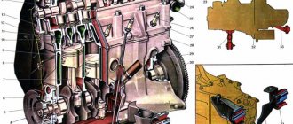
Electrical diagram of UAZ Patriot until 2007
The electrical circuit diagram is shown in Fig. 1
Rice. 1
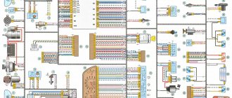
The conductors of the electrical circuit connections are made of stranded copper wire, enclosed in polyvinyl chloride (PVC) insulation with one- or two-color markings in accordance with the electrical circuit. Groups of conductors are combined into electrical bundles. A common cause of electrical wiring failure is the shorting of wires inside the harness due to a short circuit. In this case, it is necessary to “gut” the entire harness to make sure that there are no internal melts or short circuits along its entire length. In the event of a breakdown in the electrical connections between the nodes of the electrical circuit, the connections from a specific actuator to the node control unit should be “ringed” in accordance with the diagram shown. The designation of the circuit elements is shown in Fig. 2
Fig.2
Car diagrams. How to read them?
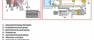
A1 — engine control controller (unit); A2 — electric fuel pump module with level sensor; A3 - instrument cluster or panel; A4 — immobilizer (automobile anti-theft system APS); A5 - trip computer; A6 — accelerator pedal module (E-gas); A7 — throttle device with electric drive; B1 - throttle position sensor; B2 - mass air flow sensor; B3 - coolant temperature sensor; B4 - air temperature sensor; B5 - knock sensor; B6 - oxygen sensor No. 1; B7 - oxygen sensor No. 2; B8 - rough road sensor; B9 - fuel temperature sensor; B10 — sensor for the presence of water in the fuel coarse filter; B11 — sensor for the presence of water in the fine fuel filter; B12 — fine fuel filter clogging sensor; BP1 — intake air absolute pressure sensor; BP2 - emergency oil pressure alarm sensor; BP3 - air conditioner refrigerant pressure sensor; BP4 — fuel pressure sensor (diesel); BR1 — synchronization sensor (crankshaft position); BR2 — phase sensor (camshaft position); BV1 - vehicle speed sensor; E1...E4 - glow plugs (diesel); F1..F4 - spark plugs for cylinders 1...4; FU1..FU6 - fuse; HL1 - MIL lamp for engine diagnostics; HL2 — IMMO lamp for immobilizer status (ALS unit); HL3 — EOBD diagnostic indicator (lamp); HL4 — indicator (lamp) of the presence of water in the fuel; HL5 - indicator (lamp) of clogging of the fine fuel filter; GB1 - rechargeable battery; KA1 - main relay; KA2 - electric fuel pump relay; KA3, KA4 - relay for electric fans No. 1 and No. 2 for engine cooling; KA5 - air conditioning compressor clutch relay; KA6 - glow plug relay (diesel); KA7 - main relay No. 2 (additional); KA8 — cooling fan electric coupling relay; KA9 — fuel heater relay in the filter; L1 — immobilizer transceiver antenna; M1 - electric fuel pump; M2, M3 - electric fans EVO-1 and EVO-2; PF1 - tachometer; PS1 - coolant temperature indicator; TV1, TV2 - two-terminal ignition coil; TV3 - ignition module with two-terminal coils; TV4..TV7 - individual ignition coils; TV8 - four-terminal ignition coil; W1..W4 - high-voltage ignition wires; SA1 - ignition switch; SA2—mass switch; SA3 - air conditioner switch; SA4 — two-channel brake pedal switch; SA5 — clutch pedal switch; XS1 — diagnostic connector; XS2 — nozzle connector; Y1..Y4 — fuel injection nozzles (gasoline or diesel); Y5 — additional air regulator (idle speed); Y6 — adsorber purge valve; Y7 - electric coupling of the air conditioning compressor; Y8 - exhaust gas recirculation valve; Y9 — electric coupling for turning on the cooling fan; * — the component can be installed as an additional kit.
One of the features of modern Russian-made cars is the presence of a large number of various devices and systems that provide more comfortable operation of the cars. UAZ Patriot cars were no exception. What elements does the UAZ Patriot electrical circuit include and how can you identify electrical problems? We will talk about this below.
[Hide]
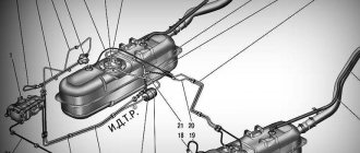
Electrical diagram of UAZ Patriot from 2007 to 2012
Fig.3
The designation of the elements is shown in Fig. 4
Rice. 4
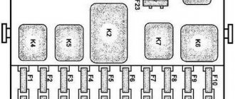
In the event of a failure of electrical equipment, you should first check the serviceability of the relays and fuses in accordance with the diagram in Fig. 5:
Rice. 5
When replacing failed fuses, first of all you should make sure that there are no short circuits in the wiring, that the device it serves is in good condition, then install the fuse in exact accordance with the rating (current) indicated on the fuse block. One fuse can serve several electrical components; you should make sure that all elements are in good working order.
How to determine the malfunction?
How to determine the presence of voltage in a car's electrical wiring:
- To check, you will need a test light; you need to solder two wires to it. One probe of the tester must be connected to the negative terminal of the battery or the car body, and the second to the section of the electrical circuit being tested. In order to more accurately determine the lack of voltage, it is advisable to connect the second probe as close as possible to the battery or fuse.
- If, as a result of connection, the control panel lights up, this may indicate that there is voltage on the device being tested.
- In the same way, you need to check other components of the electrical network. If it happens that the light source does not light up, then the cause of the malfunction must be sought in the area between the point being tested and the last place where the voltage was. Typically, wiring malfunctions are associated with poor contact, so the quality of the connection should be diagnosed. In addition, depending on the section of the circuit being tested, there may be voltage on it only when the key is turned in the lock (video author: Dmitry Sherstnev).
If you have any suspicions about unreliable grounding, you can check it like this:
- First of all, turn off the ignition and disconnect the terminals from the battery. Then, using the same control light, one of its probes should be connected to the Patriot body.
- The second contact from the tester is connected to the grounding point, in particular, we are talking about the area that you are testing.
- If after connecting the light comes on, this indicates that everything is in order with the grounding. Accordingly, you can begin checking other areas.
One of the problems that occurs in the operation of wiring is a violation of integrity, that is, a break or damage to the cable.
To diagnose this problem, do the following:
- First of all, the voltage is disconnected from the electrical circuit; for this, the terminals are disconnected from the battery. Checking the continuity of the circuit is carried out using a test light, as well as a connected power source.
- Then one probe from the testing device must be connected to the positive end of the circuit being tested, the second to ground, that is, the car body. Or two probes from the light bulb are connected to both ends of the area being diagnosed. If the lamp lights up as a result of the connection, this indicates that the circuit is intact and there is no damage in it. Accordingly, if the light does not light up, then the area is damaged.
- The switch is also diagnosed; the tester probes must be connected to the terminals of the device. When the switch is turned on, the lamp should light up.