Basic engine malfunctions (crank and gas distribution mechanisms)
Let's look at the most common malfunctions of car engines and list the main reasons for their occurrence. The engine runs erratically or stalls at idle. Main reasons: malfunction of the power supply system, ignition; increased wear of the crank and connecting rod (CVD) and gas distribution (GRM) mechanisms.
The engine develops insufficient power. The main reasons: poor filling of the cylinders with the fuel-air mixture; insufficient compression; engine overheating; malfunction of the power supply system, ignition; increased wear of the crank mechanism and gas distribution mechanism; burnout of the head gasket.
Increased fuel consumption and increased toxicity of exhaust gases. The main reasons: malfunctions of the power supply system, ignition and gas distribution mechanism.
Smoky exhaust. The main reasons: with a black exhaust - over-enrichment of the mixture, with a blue exhaust - combustion of oil in the exhaust system due to an increased level in the engine crankcase or wear of the cylinder-piston group.
Silenced shots. The main reasons: loose closure of the exhaust valve or its burning; rich mixture.
Popping sounds in the intake manifold. The main reasons: loose closure of the intake valve; lean mixture.
Increased oil consumption. The main reasons: wear or coking of the piston rings; wear of pistons and cylinder walls, oil seals and valve guides; crankcase ventilation system clogged.
Insufficient engine oil pressure. The main reasons: wear of the main and connecting rod journals and crankshaft bearings; lubrication system malfunctions.
Knocks and noises when the engine is running. The main reason: wear of parts of the crank and gas distribution mechanisms of the engine.
Malfunctions of the crank mechanism
Malfunctions of the crank mechanism are the most serious engine malfunctions. Their elimination is very labor-intensive and costly, since it often involves a major overhaul of the engine.
Malfunctions of the crank mechanism include:
- wear of main and connecting rod bearings;
- wear of pistons and cylinders;
- piston pin wear;
- breakage and sticking of piston rings.
The main causes of these malfunctions are:
- development of the installed engine life;
- violation of engine operating rules (use of low-quality oil, increased maintenance periods, prolonged use of the vehicle under load, etc.)
Almost all malfunctions of the crank mechanism (CCM) can be diagnosed by external signs, as well as with the help of simple instruments (stethoscope, compression gauge). Malfunctions of the crankshaft are accompanied by extraneous noise and knocking, smoking, loss of compression, and increased oil consumption.
External signs and corresponding malfunctions of the crankshaft
- a dull knock at the bottom of the cylinder block (increases with increasing speed and load);
- decrease in oil pressure (warning light is on)
- floating dull knock in the middle part of the cylinder block (increases with increasing speed and load, disappears when the corresponding spark plug is disconnected);
- decrease in oil pressure (warning light is on)
- loud knocking noise (clacking noise) on a cold engine (disappears when warmed up);
- blue exhaust smoke
- a loud knocking sound in the upper part of the cylinder block in all engine operating modes (increases with increasing speed and load, disappears when the corresponding spark plug is disconnected)
- blue exhaust smoke;
- decrease in oil level in the engine crankcase;
- engine running intermittently
If wear of the main and connecting rod bearings is diagnosed, further operation of the vehicle is strictly prohibited . In other cases, you must move to the garage or car service center with utmost caution.
Source
Knock in crankshaft main bearings
This is usually a low-pitched metallic thud. It is heard in the lower part of the cylinder block and is detected when the throttle valve is opened sharply at idle. Excessive crankshaft clearance causes a sharper knock with uneven intervals, especially noticeable when the crankshaft speed is gradually increased and decreased. Causes of knocking and ways to eliminate it:
- ignition too early. Check and adjust the ignition timing;
- insufficient oil pressure. See the chapter “Main lubrication system malfunctions”;
- increased clearance between the crankshaft journals and the main bearing shells. Contact a service station to check and, if necessary, to regrind the journals and replace the liners;
- increased clearance between the thrust half-rings and the crankshaft. With the engine off, check the axial free play of the crankshaft by pressing and releasing the clutch pedal. In this case, the movement of the front end of the crankshaft should be no more than 0.35 mm. In case of greater axial free play, contact a service station to replace the crankshaft thrust half-rings.
Knock of connecting rod bearings
Usually the knock of the connecting rod bearings is sharper than the knock of the main bearings. It can be heard in the upper part of the cylinder block when the engine is idling when the throttle valve is opened sharply. The location of the knock can be easily determined by turning off the spark plugs one by one.
Causes of knocking and ways to eliminate it:
- insufficient oil pressure. See the chapter “Main lubrication system malfunctions”;
- Excessive clearance between the crankshaft connecting rod journals and the bearings. At a service station, grind the crankshaft journals and replace the bearings.
Knock of pistons and piston pins. The knocking sound of the pistons is usually quiet, muffled, caused by the “beating” of the piston in the cylinder: It is best heard at low crankshaft speeds under load. The knocking sound of the fingers is distinct and sharp, increases with increasing crankshaft rotation speed and disappears when the cylinder is turned off. It can be heard in the upper part of the cylinder block.
Causes of knocking and ways to eliminate it:
- increased clearance between pistons and cylinders. Repair the engine by boring and honing the cylinders and replacing the pistons;
- Excessive clearance between the piston rings and the grooves on the piston. Replace rings or piston with rings;
- Excessive clearance between the pin and the hole in the piston. Replace piston and pin.
What is a KShM and why is it needed?
During operation, the engine must provide some kind of constant movement, and it is most convenient for this to be uniform rotation. However, the power part (cylinder-piston group, CPG) produces translational motion. This means that we need to make sure that one type of movement is transformed into another, and with the least losses. This is why the crank mechanism was created. In essence, a KShM is a device for receiving and converting energy and transmitting it further to other nodes that are already using this energy.
Operating principle of the crank mechanism
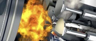
During the main stroke of a car engine - the power stroke (expansion), burning gases press on the piston, and it moves down - from top dead center to bottom, thereby transferring energy through the pin and connecting rod to the crankshaft. The connecting rod can rotate to a limited extent both around the axis of the piston pin and around the crankpin of the crankshaft, and thus the translational movement of the piston turns into a rotational one.
This is interesting: Tuning Subaru Impreza
It is worth noting that during the remaining strokes, the crankshaft, through the connecting rod, on the contrary, imparts reciprocating motion to the piston. Where does he get it? From the “working” cylinders, the energy of the crankshaft and flywheel, and when starting, the starter.
Breakdowns and problems of the crank mechanism
Almost all parts of the crankshaft drive are friction pairs, which is clearly confirmed by the diagram of the kinematics of the vehicle drive. If the diagnosis of this internal combustion drive mechanism reveals malfunctions, a major overhaul of the engine is necessary, since it is completely disassembled.
Technical features of crankshaft drive malfunctions include wear of friction parts. The main breakdowns are:
- stuck rings on the pistons - due to high metal production, play appears, misalignment occurs and the piston becomes jammed inside the cylinder;
- wear of the piston pins - instead of a fixed size between the crankshaft/piston, the distance becomes floating, the torque characteristics change;
- development of the piston group - the cylinder mirror or piston surface is ground off, the characteristics of the internal combustion engine change;
- Bearing wear – the connecting rod or main bearings are worn down, causing shock loads on the shaft.
The main causes of malfunctions are prolonged loads, lack of maintenance, poor quality of lubrication or exhaustion of the drive life.
Position of piston rings
The specified malfunctions of the crank mechanism are diagnosed based on the following symptoms:
- interruptions in engine operation;
- a constant decrease in the lubricant level in the crankcase;
- exhaust gases take on a blue tint.
The breakdown cannot be repaired at home, as it requires a highly qualified technician and complete disassembly of the engine.
Wear of pistons and pins
These specific malfunctions of the crank mechanism are identified by the following signs:
- fingers - regardless of the operating mode of the engine, a loud knocking sound is heard in the upper part of the cylinder block, which disappears when the spark plug is unscrewed, and increases as the shaft speed increases;
- pistons - blue exhaust, knocking sound similar to the previous case, but only at idle, after warming up it usually disappears.
After diagnosing this malfunction, a major overhaul of the internal combustion engine is required.
Wear of connecting rod and main bearings
Repair of the crank mechanism will inevitably be required when the bearing life is exhausted, as evidenced by the following factors:
- connecting rod bearing - a warning light indicates insufficient lubricant pressure, a dull, floating knocking sound comes from the middle part of the cylinder block;
- main bearing - the warning light lights up, indicating low oil pressure, a dull knock occurs in the lower part of the cylinder block.
By analogy with the previous options, it will not be possible to do without major repairs.
Operating principle and purpose
Unlike an electric motor, the operating principle of a crankshaft in internal combustion engines is much more complicated:
- the pistons are alternately pushed out of the cylinders when the fuel mixture is ignited;
- connecting rod parts of complex configuration are hinged inside them;
- the crankshaft has a U-shaped reciprocal seating surface for the lower head of the connecting rod, which ensures displacement from the axis of rotation of the shaft;
- due to the fixed distance between the piston and the crankshaft, the connecting rod describes an amplitude in the form of a figure eight, due to which the translational movement from the cylinders is converted into torque on the shaft.
The main purpose of the consumable elements of the flywheel (liners, bushings, rings) is to increase the service life of this unit. Since the number of cylinders reaches 16 in modern cars, the design and operation of the cylinder head mechanism must be perfectly balanced.
2. Adjustment work and engine maintenance (timing, crank mechanisms)
If necessary, and periodically for older engine models, during maintenance the cylinder head fastening is checked in a certain sequence (Fig. 1) with a tightening torque individual for each engine.
The general principle of tightening: bolts begin to be tightened from the center, moving towards the periphery in a spiral. The cast iron head is fastened in a hot state, and the aluminum alloy head is fastened in a cold state.
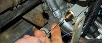
After every 50...200 thousand km (depending on the engine model), the timing belt is changed. After installing the timing belt, check and, if necessary, set the required tension. The check is carried out using a special device for measuring belt tension, and if it is absent, the correct tension is checked by turning the belt by hand: the belt must rotate 90° around its axis. The belt is tensioned by a tension roller.
Rice. 1. Tightening order of bolts (1…10) of the cylinder head
A common device for measuring belt tension is a dynamometer (Fig. 2). When measuring, bar 1 is supported on belt pulleys 6 and, pressing handle 3 until the shoulder of rod 5 stops in thrust sleeve 2, the force applied to the belt is determined using scale 4 of the dynamometer.
Rice. 2. Diagram of a device for determining belt tension: 1 - bar; 2 - thrust bushing; 3 - handle; 4 — dynamometer scale; 5 — rod collar; 6 - belt pulleys
To determine the belt tension, instruments are used that use the principle of a string - at different tensions it produces sounds of different octaves (Fig. 3). To determine sound waves, a special acoustic device has been created, which is brought to the belt branch. Belt tension is measured by the belt vibration produced by pulling the belt with your finger and releasing it, and the reading is confirmed by an audible signal. The display of the device displays a certain oscillation frequency (in hertz) of the corresponding degree of tension. The tuning frequency is compared with reference data.
During vehicle operation, as a result of wear and heating of the mechanical parts of the timing belt, the gap between the valve levers (rocker arms) and the camshaft cams changes (in other types of engines - between the camshaft and pushers, between the rocker arms and valves). Therefore, periodically (approximately every 30 thousand km), as well as during any repairs of the mechanism or removal of the cylinder head, this gap should be checked and, if necessary, adjusted in engines with a mechanical valve drive.
Rice. 3. Voltage measurement using sound waves: a - measurement principle; b - measuring device
The size of the thermal gap is individual for each engine. The technical characteristics of engines may indicate thermal clearances for both a cold and a hot engine; for a hot engine, the gap can be either larger or smaller depending on the design of the gas distribution mechanism.
An engine is considered cold if the coolant temperature is below 35 °C, which is achieved when the engine cools down after warming it up for at least 4 hours at an ambient temperature of 20 °C. An engine is considered hot if the coolant temperature in it is about 80 °C (the moment the large fluid circulation circuit is turned on).
Check and adjust the thermal clearances of the valves with the valves closed, i.e. at the maximum distance of the top of the camshaft cam from the rocker arm (pushrod, pushrod) of the valve. This shaft position can be achieved in various ways. The gaps are checked using a probe representing a set of plates with a thickness of 0.02...0.50 mm (Fig. 4).
Rice. 4. Adjusting the gaps in the gas distribution mechanism: 1 - rod; 2 - lock nut; 3 - adjusting screw; 4 - screwdriver; 5 — rocker arm; 6 - dipstick; 7 - valve
The most common method is to first adjust the valve clearances of the first cylinder; at the same time, its piston is at TDC on the compression stroke. The compression stroke is determined by the increase in air pressure in the cylinder when the piston moves to TDC: it is necessary to unscrew the spark plug (injector), close its hole in the cylinder block with a special whistle (plug, finger) and turn the crankshaft until the whistle sounds (plug is pushed out, pressure sharply increases on the finger).
After adjusting the thermal clearances of the valves of the first cylinder, the clearances of the remaining valves are adjusted in the order of their operation, each time turning the crankshaft 180° (for 4-cylinder engines), 120° (for 6-cylinder engines) or 144° (for 5-cylinder engines).
The size of the valve-seat gap can be indirectly assessed by the amount of compressed air breaking through the leaks of closed valves. To do this, first remove the rocker arm rollers, ensuring simultaneous closing of the valves in all cylinders, then the injectors (or spark plugs), and then compressed air is supplied to the combustion chamber from the compressor at a pressure of 0.20...0.25 MPa. Depending on the purpose of the valve being tested (inlet or outlet), the gas flow indicator KI-13671 (see Fig. 16) is installed on the inlet pipe of the air cleaner or on the outlet pipe. The amount of gas flow through the indicator is determined similarly to measuring the amount of crankcase gases. If the air leakage of one of the valves exceeds the permissible limit, then the cylinder head is subject to routine repairs.
When diagnosing a crankshaft when the engine is not running, the gaps in the upper and lower heads of the connecting rod are determined. For this purpose, the device KI-11140 is used. The base 5 of this device (Fig. 5) is secured in place of the nozzle using a removable flange 4. A stop 8 moves inside the housing, connected to the indicator leg 1. The housing has a special pipe through which the combustion chamber is connected via a hose to the control valve of the KI-13907 compressor-vacuum unit, which creates excess pressure or vacuum in the combustion chamber.
Rice. 5. Diagram of the KI-11140 device for determining gaps in the crank mechanism : 1 - indicator; 2 — indicator stand; 3 - mandrel; 4 - removable flange; 5 - base; 6 - ring; 7 - tip; 8 - stop
To carry out measurements, the piston in the cylinder being diagnosed is set to the TDC position and excess pressure is created using a KI-13907 type installation. The piston moves down, eliminating all gaps in the crankshaft. Then the stop 8 is brought into contact with the piston, the indicator scale 1 is set to zero and a vacuum is created using the setting. The piston begins to move upward and alternately eliminates the gaps in the crankshaft: piston - pin, pin - bushing of the upper head of the connecting rod, connecting rod bearing - crankshaft journal. After the piston stops, the total clearance in the crankshaft is determined using the indicator scale. Since the piston moves in steps, the components of the total gap can be determined. This method is very labor-intensive and requires a compressor-vacuum installation. During engine maintenance, work is also carried out to check exhaust tract parts (exhaust pipe, muffler, etc.), fastening engine mounts, and fastening the engine oil pan.
Mechanism design
The classic crank mechanism was known back in Ancient Rome. A similar principle was used in the Roman sawmill, only there the rotation, under the influence of the river flow, of the water wheel turned into a reciprocating motion of the saw.
Steam engines also used a crankshaft, similar to that now used in automobile internal combustion engines (ICE). Only in it the piston was connected to the connecting rod through a rod and a low-pressure cylinder. A similar design is sometimes used in internal combustion engines to this day.
In so-called crosshead engines, the piston is rigidly connected to the crosshead - a part that moves along fixed guides in one dimension, like the piston, through a rod, and then according to the usual pattern - a connecting rod with a crankshaft. This allows you to increase the piston stroke, and sometimes makes the cylinder double-sided; in such designs, another combustion chamber is added. This type of flywheel is most often used in marine diesel engines and other large equipment.
The crank mechanism consists of two main groups of parts - moving and stationary:
- The moving parts of the crankshaft include the following parts: pistons, which, together with rings and pins, are combined into a piston group, connecting rods, a crankshaft (in colloquial abbreviation - crankshaft), crankshaft bearings and a flywheel.
- The fixed ones are the crankcase combined with the cylinder block, cylinder liners, and the cylinder head. These also include the sump (lower crankcase), crankshaft half rings, flywheel and clutch housings, as well as brackets and fasteners.
Sometimes a cylinder-piston group is also distinguished, which includes the piston and cylinder liner.
Cylinder block
The cylinder block is now inseparable from the crankcase. This, by the way, was not always the case - on older engines (Zaporozhets, for example), they could be manufactured separately. It is the crankcase, together with the cylinder block, that is the main structural unit of a car engine.
All the useful work of the engine takes place inside the block. The lower crankcase (pan) is attached to the cylinder block at the bottom, the cylinder head at the top, the flywheel housing, fuel and exhaust systems and other engine parts at the rear. The block itself is attached to the car chassis through special “pillows”.
The material from which this important part of the engine is made is most often either aluminum or cast iron. Composite materials can also be used on sports cars. Removable liners are pressed into the block, which facilitate the stroke of the pistons and the maintainability of the block - that is, its boring for “repair” pistons and rings. The sleeves are made of cast iron, steel or composite alloys. There are two types of sleeves:
- “dry” - when the outer surface of the liners is not washed by coolant;
- “wet” - when the liner is cooled from the outside by a flow of liquid.
Each option has its own advantages and disadvantages.
Pistons
A piston is a metal part that has the shape of a glass, and in some automobile enterprises, drivers and car mechanics with experience used old pistons, cleaned of carbon deposits, as glasses. However, its main purpose, naturally, is not this, but to convert the potential energy of pressure and thermal energy of gas temperature into the kinetic energy of rotation of the crankshaft at the moment of the power stroke.
During the intake stroke, it serves as a pump that draws in air or a combustible mixture, during the compression stroke it compresses it, and during the exhaust stroke it helps remove exhaust gases. During the power stroke (more precisely, a little earlier), the mixture ignites (or the injector injects fuel on diesel engines), and the burning gases put pressure on the piston, forcing it to do the work of converting thermal energy into kinetic energy.
This is interesting: Selecting and installing an armrest in a Chevrolet Cruze
The piston of a modern automobile engine is most often made of aluminum-based alloys. They provide good removal of excess heat, and are also quite lightweight.
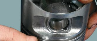
The components of a car engine piston are the bottom, the sealing part and the skirt. The piston is connected to the connecting rod using a pin located in the skirt. To ensure a tight connection between the piston and the cylinder wall, piston rings are used.
Piston rings
These are flat, open (with a gap of a few tenths of a millimeter) steel or cast iron rings that fit into special grooves on the sealing part of the piston. They serve several purposes:
- Seal. High-quality, unworn rings increase compression (pressure in the cylinder).
- Heat transfer. Compression rings transfer excess heat to the cylinder liner, preventing engine overheating.
- They do not allow engine oil to pass from the crankcase into the combustion chamber, but leave a small layer of oil on the walls of the liner to lubricate the cylinder. The lowest ring is called the oil scraper ring. Its design is specially designed for this task.
Piston pins
The piston pin is needed to connect the piston to the connecting rod. It is located in the inner part of the piston skirt and is a metal cylinder, vaguely similar to a finger (hence the name). The connecting rod is not firmly attached to the pin, because it is necessary to ensure the most even transmission of torque from the piston to the connecting rod and beyond. The fingers are usually made of alloy steel.
Fingers are divided into fixed and floating. The fixed one is rigidly attached to the piston skirt, and only the connecting rod moves on it, and the floating pin, like in a piston skirt, can rotate on the connecting rod. Nowadays, car engine designs are dominated by floating pins, which provide more complete and smooth transmission of torque and reduce the load on crankshaft parts.
connecting rod
In order to transmit torque from the piston to the crankshaft, a connecting rod connects these two important parts. To ensure that repairing the connecting rod does not cause any particular difficulties, it uses special liners, actually a collapsible plain bearing, although in some engines with low crankshaft rotation speeds, Babbitt liners are still used, and in high-speed engines, in both heads of the connecting rod (both the lower and the lower). and top) rolling bearings are installed. The shape of the connecting rod is similar to a lever or an I-beam wrench. Its upper, usually one-piece head connects it to the piston pin, and the lower, detachable head connects the connecting rod to the crankshaft. Connecting rods are most often made from alloy steel, sometimes from carbon steel.
Crankshaft
The crankshaft, or crankshaft for short, is one of the most important parts of the engine, however, there are no unnecessary parts. It has the shape of a shaft with “curvatures” in the direction to which the engine connecting rods are attached through axles. It consists of the following parts:
- Shakey. They are needed to secure the crankshaft to the crankcase and the connecting rods to it. They are divided into main and connecting rod. On the main shafts the crankshaft itself is attached to the crankcase, on the connecting rod journals the connecting rods are attached to the crankshaft.
- The cheeks are a kind of “knees” of the crankshaft; they are the ones that rotate around the axis of the crankshaft. The crankshaft cheeks are connected by the main and connecting rod journals.
- Front output shaft. Power take-off pulleys are attached to it to drive the camshaft, generator cooling system and other units through a belt, chain or gears.
- Rear output shaft. It is connected to the flywheel and serves to take power for the “main purpose” of the car - to move.
The crankshaft design also includes additional parts, such as counterweights, to compensate for shaft vibrations that occur under shock loads.
Crankshafts are most often made of either steel or high-quality light cast iron. Cast iron crankshafts are made by casting, steel crankshafts by stamping.
Crankcase
The crankcase, cast together with the cylinder block, is the main part of the car engine, one might say the engine frame. It is on the crankcase that the main parts of the engine are fixed, the crankshaft rotates in it, the pistons move in the cylinders and the direct process of converting the energy of fuel combustion into the energy of rotation of the wheels of your car takes place.
The crankcase is also the main location for the engine oil that lubricates the engine. A sump, the lower part of the crankcase, is also designed to store oil.
KShM device
Strictly speaking, the crankshaft of a car consists of the crank itself, connecting rods and pistons. However, talking about a part without talking about the entire structure would be completely wrong. Therefore, the design and purpose of the KShP and related elements will be considered in a comprehensive manner.
Crankshaft design: (1 - main bearing on the main journal; 2 - connecting rod bearing on the connecting rod journal; 3 - connecting rod; 4 - piston pin; 5 - piston rings; 6 - piston; 7 - cylinder; 8 - flywheel; 9 - counterweight; 10 - crankshaft.)
- The cylinder block is the beginning of all movement in the engine. Its components are pistons, cylinders and cylinder liners in which these pistons move;
- Connecting rods are the connecting elements between the pistons and the crankshaft. Essentially, the connecting rod is a strong metal bridge, which is attached to the piston on one side using a connecting rod pin, and the other is fixed to the crankshaft journal. Thanks to the pin connection, the piston can move relative to the cylinder in one plane. In the same way, the connecting rod covers the crankshaft seat - the connecting rod journal, and this fastening allows it to move in the same plane as the connection with the piston;
- Crankshaft - a crankshaft of rotation, the axis of which passes through the shaft toe, the main (support) journals and the flywheel flange. But the connecting rod journals extend beyond the axis of the shaft, and due to this, when it rotates, they describe a circle;
- A flywheel is an essential element of a mechanism that accumulates rotational inertia, thanks to which the engine runs smoother and does not stop at a “dead point.”
These and other elements of the flywheel can be divided into moving elements, those that perform direct work, and fixed auxiliary elements.
Mobile (working) group of KShM
As the name implies, the moving group includes elements that are actively involved in the operation of the engine.
- Piston. When the engine is running, the piston moves in the cylinder liner under the action of the buoyancy force during fuel combustion on the one hand, and by rotation of the crankshaft on the other. To seal the gap between it and the cylinder, there are piston rings (compression and oil scraper) on the side surface of the piston, which seal the gap and prevent loss of power during fuel combustion.
Piston group structure: (1 - oil-cooling channel; 2 - combustion chamber in the piston bottom; 3 - piston bottom; 4 - groove of the first compression ring; 5 - first (upper) compression ring; 6 - second (lower) compression ring; 7 - oil scraper ring; 8 - oil nozzle; 9 - hole in the connecting rod head for supplying oil to the piston pin; 10 - connecting rod; 11 - piston pin; 12 - piston pin retaining ring; 13 and 14 - piston ring partitions; 15 - flame belt.) - Connecting rod. This is the connecting element between the piston and crankshaft. The upper head of the connecting rod is attached to the piston using a pin. The lower head has a removable part so that the connecting rod can be placed on the crankshaft journal. To reduce friction, connecting rod bearings are installed between the crankshaft journal and the connecting rod head - plain bearings in the form of two plates curved in a semicircle.
Connecting rod device - Crankshaft. This is the central part of the engine, without which it is difficult to imagine its operating principle. Its main part is the axis of rotation, which simultaneously serves as a support for the crankshaft in the cylinder block. The elements protruding beyond the axis of rotation are intended to be attached to the connecting rods: when the connecting rod moves down, the crankshaft allows it to describe a circle with its lower part simultaneously with the movement of the piston. Just as in the case of connecting rods, the crankshaft journals rest on plain bearings - liners.
Crankshaft device - Flywheel. It is attached to a flange on the end of the crankshaft. The flywheel rotates with the engine shaft and partially dampens the jerky loads that are inevitable in any internal combustion engine. But the main task of the flywheel is to spin the crankshaft (and with it the cylinder-piston group) so that the pistons do not freeze at a “dead point”. Thus, part of the engine power is used to support the rotation of the flywheel.
Flywheel device
Fixed group KShM
The fixed group can be called the outer part of the engine in which the control gear is located.
- Cylinder block. Essentially, this is a housing in which the cylinders, cooling system channels, camshaft, crankshaft seats, etc. are located directly. It can be made from cast iron or an aluminum alloy, and today manufacturers are increasingly using aluminum to make the structure lighter. For the same purpose, instead of solid casting, stiffening ribs are used, which lighten the structure without loss of strength. On the sides of the cylinder block there are seats for auxiliary engine mechanisms.
Cylinder block - Cylinder head (cylinder head). It is installed on the cylinder block and closes it from above. The cylinder head has holes for valves, intake and exhaust manifolds, camshaft mounts (one or more), and mounts for other engine elements. A gasket (1) is attached to the cylinder head from below - a plate that seals the joint between the cylinder block and the cylinder head. It has holes for cylinders and mounting bolts. And on top is the valve cover (5), which closes the cylinder head from above when the engine is assembled and ready to start. Valve cover gasket. This is a thin plate that fits around the perimeter of the cylinder head and seals the joint.
Cylinder head structure: (1 - cylinder head gasket; 2 - cylinder head; 3 - oil seal; 4 - cylinder head cover gasket; 5 - valve cover; 6 - pressure plate; 7 - oil filler plug; 8 - plug gasket; 9 - valve guide; 10 — installation sleeve; 11 — bolt for securing the block head.)
List of KShM malfunctions
The main troubles that can happen to the crank mechanism:
- Both connecting rod and crankshaft main journals are subject to wear and mechanical damage.
- Wear, mechanical damage and even melting can also threaten the crankshaft journal liners (bearings).
- “Diseases” of piston rings are coking by incompletely burned combustion products (hydrocarbons are oxidized only to carbon), their occurrence and even breakage, which can lead to fatal consequences.
- The cylinder-piston group is also subject to wear. In modern “engines” this is not so noticeable; after all, they are created with the latest technology, but each part has a finite resource.
- Carbon deposits may be deposited on the piston crown.
- Cracks may appear in parts, they may burn out, break off, or even melt.
- The engine may even seize.
Basic malfunctions of the crank mechanism
problems today
, causes and methods
of eliminating
the crank mechanism.
The engine does not start.
Cause
: weak compression in the cylinders due to
wear of
the piston group (liners, pistons, rings).
Elimination
: Replace worn parts.
The engine runs intermittently and does not develop rated power.
several reasons
.
The first
reason
: water entering the cylinders from the
cooling
.
Elimination
: water entering the
cylinders
, tighten the cylinder head nuts,
replace
the gasket
Second
reason
:
the piston
rings are worn out.
Elimination
: Replace the rings.
Third
reason
: The exhaust
pipe
Remedy
: Clean the pipe.
Smoky exhaust gases.
Cause
: Coking of piston rings
Elimination
: Remove the pistons and clean the rings.
Cause
: Wear of the piston group.
Elimination
: Replace worn parts
of the piston
group.
Cause
: The engine is not warmed up.
Elimination
: Warm up the engine.
Cause
: water entering the cylinders.
Elimination
: Eliminate water ingress.
Knocks in the engine.
Cause
: the piston pins, holes in
bosses
and the upper head of the connecting rod
Elimination
: Replace worn parts.
Cause:
Worn pistons and liners
Elimination
: Replace worn parts.
- Loud knocking noises when the engine is running under load.
Cause
: the
crankshaft journals
Elimination
: Replace worn parts.
Source
Oil getting into the coolant
There is a decrease in the oil level in the engine, an oil film appears in the expansion tank, and the color of the coolant changes from gray to dark brown.
To check, remove the cylinder head, fill the cooling jacket of the cylinder block with water and supply compressed air to the vertical oil channel of the cylinder block (near the hole for bolt 5, see Fig. 22). If air bubbles are observed in the water filling the cooling jacket, then the cause of the malfunction is cavities or cracks in the jumpers between the oil line and the cooling jacket of the cylinder block. In this case, the cylinder block must be replaced.
If the oil passages in the cylinder block are sealed, then oil may be leaking into the coolant from the oil passages in the cylinder head. In this case, it is necessary to check the tightness of the cylinder head (see the chapter “Main malfunctions of the gas distribution mechanism”).
Coolant getting into the oil
The fluid level in the expansion tank is constantly decreasing, and the oil level is increasing. The oil changes color from gray to milky white.
The causes of the malfunction are cavities, porosity or cracks in the walls of the cooling jacket of the cylinder block. To check this defect, it is necessary to disassemble the engine and check the tightness of the cooling jacket of the cylinder block in a bath of water, supplying compressed air into the jacket at a pressure of 2.3 kgf/cm2.
If air etching is not observed, then it is necessary to check the tightness of the cylinder head (see the chapter “Main malfunctions of the gas distribution mechanism”).
During the operation of the vehicle, the normal operation of the crank mechanism may be disrupted as a result of certain malfunctions. The main ones are: wear of the main and connecting rod bearings of the crankshaft, shaft journals, piston pins, holes in the piston bosses or bronze bushings in the upper heads of the connecting rods, pistons and cylinder liners, a decrease in compression in the cylinders.
Signs of wear on the main and connecting rod bearings of the crankshaft and shaft journals are dull knocks that can be heard when switching to a high rotation speed. The causes of this malfunction may be: loosening of the bearing caps, use of the wrong type of oil, loosening of the flywheel on the shaft.
The main and connecting rod bearings should be tightened or the bearings replaced, the flywheel mounting bolts should be tightened and cotter pinned, and the oil should be changed.
Signs of malfunctions in the operation of the crankshaft
Extraneous knocking noises in the engine may alert you. Perhaps this is due to detonation or you came across a low-quality fuel. The consequences of both detonation and low-quality fuel can be tragic. The sound during detonation is louder, but a dull sound may indicate that the crankshaft journals are worn out. If it is very loud and occurs not only with a sharp increase in speed (for example, if you quickly set off), then it is quite possible that the crankshaft journal liners begin to melt. Perhaps the cause is oil starvation, but one way or another - to the service.
Smoke from the engine can also tell a lot. If it is gray, it means that oil is entering the combustion chamber. Perhaps the culprit is the timing valve seals, or perhaps the problem is in the piston rings. The accumulation of carbon deposits on pistons and cylinders leads to increased friction and increased wear of parts. If the problem is in the rings, then the compression will be reduced, although the decrease in compression may be due to other reasons.
KShM maintenance
First of all, general advice: “the machine loves affection, cleanliness and lubrication.” You should check the oil level on time, prevent the engine from overheating and refuel only with high-quality fuel. Serious problems with the crankshaft drive can only be solved in a car service center. Of course, there are car enthusiasts who can independently bore the cylinder to repair size, but this is still typical for not the newest cars.
In “coked” engines, decoking can be carried out, which is done both with engine disassembly and with the help of special means - without it. However, such manipulations are best left to professionals. Follow maintenance deadlines.
see also
The engine exhaust can also tell a lot. So, if the exhaust gases are bluish in color and the engine oil level is constantly decreasing, this indicates wear of the cylinder-piston group. Increased consumption of engine oil and fuel and a significant decrease in power can occur due to the occurrence of piston rings (both compression and oil scraper rings, see Fig. No. 4) and increased wear on them and the cylinder (see Fig. No. 3). The occurrence of piston rings can be eliminated without disassembling the engine by pouring a special solution consisting of 50% kerosene and 50% denatured alcohol into the cylinders through the spark plug hole (for diesel engines - through the hole for the injectors or through the intake manifold). After 8-10 hours of inactivity, you need to start the engine and let it run for 10-20 minutes, then change the engine oil. This procedure allows you to significantly reduce the amount of carbon deposits (it is carbon deposits that do not allow the piston rings to move freely in the piston grooves) in the area of the piston rings and the piston crown, thereby freeing and restoring their performance.
| Figure No. 3 - Wear of the cylinder wall |
|
Crankshaft drive malfunctions can occur due to many different factors, but in most cases, improper operation is to blame. Incorrect operation. Improper operation includes: use of low-quality lubricants, low-octane fuel, installation of low-quality fuel, air and oil filters. The influence of all these factors increases significantly if they are not replaced in a timely manner. So, when using low-quality fuel, you should change the engine oil and spark plugs more often, and periodically “wash off” the deposits in the piston system with special liquids. Low-quality filters also do their job poorly, which leads to an increase in abrasive in the oil and, as a result, to increased wear of parts. The choice of engine oil should be made according to the calculated characteristics (usually they are indicated by the manufacturer); it is for them that the engine of your car is designed and you should not deviate from them. An air filter, when it is heavily contaminated, sharply reduces its throughput, which causes a high vacuum to form in the intake manifold and the filling ratio decreases - this is one of the reasons for the formation of excessive carbon deposits, a decrease in engine power and an increase in fuel consumption.
Natural wear and tear. Natural wear occurs very slowly and, as a rule, depends on operating conditions. With proper operation, the engine's mileage can reach more than 1,000,000 km, its lifespan is more than 10 years, and even more for modern engines!
Wear due to prolonged overheating (see Fig. No. 5). This type of wear most often occurs in summer and spring. In summer, overheating occurs due to increased ambient temperature, and in spring due to insulation of the engine and significant fluctuations in ambient temperature. Due to overheating, melting of the pistons, burnout of the exhaust valves and loss of elasticity in the piston rings may occur. Even short-term overheating significantly reduces the service life of the engine, which is why great attention should be paid to the engine cooling system. Everything in the cooling system is important: the fluid you use, the radiator cap, not to mention its tightness and the cleanliness of the radiator cells.