By the malfunction of the Daewoo Nexia stove, many owners of this car mean:
- The heater only blows cold air or barely warms up the interior.
- The device works, but does not direct air to the legs.
- The stove fan, speed 4 and other modes do not work.
- The mode switch does not function.
- The position of the dampers does not correspond to the settings on the control unit.
- Write about other malfunctions in the comments.
In some cases, due to reluctance to understand the problem or the inability to solve it, many Daewoo Nexia owners got rid of the car by selling it on the secondary market.
Although most test drivers believe that frequent breakdowns of the interior heater are an “incurable disease” of this car model, selling a car because of this, in our opinion, is more an emotional rather than a pragmatic act, since all the problems described above completely removable.
We'll talk about this next.
The design of the heating system of the Daewoo Nexia
To understand the reasons for the breakdown of the stove, it is important to know its design features, what elements it consists of and where its “Achilles heel” is located. It is also important to know the general design of the vehicle's heating and air conditioning system.
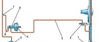
The heating, ventilation and air conditioning systems of the Daewoo Nexia are located in one block. The latter is hidden behind the instrument panel.
The block contains the following elements (see diagram below):
- Electric fan drive.
- Heat exchangers for heater and air conditioner.
- Two air supply boxes to the windshield blower nozzles and the same number of air supply boxes to the left and right ventilation nozzles.
- Upper air duct located in the center.
- Mechanisms, levers, pneumatic hoses for controlling air flow distribution, driving the temperature control damper.
The electric fan drive is one of the main elements of the system whose characteristics are important to know (repair, replacement, etc.):
- Type – centrifugal.
- Voltage 12V.
- Current strength – up to 20A.
- The height of the blades is 68 mm.
- Impeller diameter – 148 mm.
- Revolutions per minute – 3600.
It is worth mentioning the control panel, which contains:
- Handle for switching to 1,2,3,4 fan operating modes.
- Buttons for turning on the air conditioner and air recirculation modes.
- Handles for adjusting air temperature and distribution of air flows.
Main components of the Deo Nexia system
- Repair manuals
- Repair manual for Daewoo Nexia 94+.
- Main components of the system
6.4.1 Main components of the MSVT system includes the following main components: – fuel tank, pump and fuel pipelines intended for storing and supplying gasoline;
– electrical circuit for controlling the fuel pump; – fuel pressure regulator, fuel distribution pipeline and injectors; – throttle body... 6.4.2 Fuel distribution pipe Fuel distribution pipe assembly (1.5L SOHC engine) 1. FUEL DISTRIBUTION PIPE 2. INLET 3. FUEL INJECTOR 4. FUEL PRESSURE REGULATOR 5. DRAIN FITTING (ON REAR SIDE) REGULATOR ) Fuel flow through the distribution pipe...
6.4.3 Fuel injectors Fuel injector 1. INJECTOR BODY 2. GUIDE BUSHING 3. BUSHING WITH VALVE SEAT 4. VALVE SHUT-OFF 5. INJECTOR TIP 6. SPRAY PLATE 7. BOR SPRAYER STARTER 8. VALVE SPRING 9. ELECTROMAGNET HOUSING 10. ELECTROMAGNET 11. INPUT…
6.4.4 Fuel Pressure Regulator Fuel Pressure Regulator 1. VACUUM PIPE 2. O-RING 3. REGULATOR BODY 4. DRAIN PIPE FITTING 5. FITTING O-RING 6. DIAPHRAGM 7. PRESS SPRING 8. ROOF KA VACUUM CAVITY REGULATOR The fuel pressure regulator includes R…
6.4.5 Throttle Body Throttle Body (1.5L SOHC Engine) 1. IDLE VALVE ASSEMBLY 2. HOUSING ASSEMBLY 3. THROTTLE POSITION SENSOR 4. THROTTLE VALVE 5. COOLANT INLET AND OUTLET PIPE BONES 6. CHAMPER DRIVE LEVER 7. IDLE LIMIT SCREW…
6.4.6 Oil pressure switch The oil pressure switch is installed on the jumper of the engine cylinder block. The pressure relay is connected in parallel with the fuel pump relay and duplicates the power supply to the pump when the pressure in the engine lubrication system reaches 28 kPa. The pressure switch is a spare switch for the fuel pump. The only one...
6.4.7 Fuel pump activation relay The fuel pump activation relay is located to the left of the steering column under the shield. The only maintenance operation on the pump relay is to check the condition of the electrical contacts. In case of failure, the relay is replaced as an assembly.
6.4.8 Checking the fuel pump supply PERFORMANCE ORDER 1. Remove the fuel supply line hose and connect it to a suitable container made of non-fragile material. Connect the battery cable to the pump test terminal. 2. The pump flow must be at least 0.23 liters of gasoline in 15 seconds. 3. If...
6.4.9 Fuel tank Fuel tank fastening 12. NUT 13. FUEL TANK FASTENING TAPE Dismantling PROCEDURE 1. Drain the fuel from the tank. 2. While supporting the tank, remove the two metal fastening straps. 3. Lower the tank to disconnect the level sensor wire...
6.4.10 Accelerator pedal When servicing the accelerator pedal, the following requirements must be observed. The mating planes of the pedal suspension bracket and the front body shield must be free of insulating material. The mat, floor and tunnel coverings must be straight and free of wrinkles. Thread the cable into the hole...
6.4.11 Fuel filter Fastening the fuel filter A. BURNING CONNECTIONS, TIGHTEN TO 30 Nm 27. FUEL PIPE 30. FUEL FILTER 36. FUEL PIPE Remove or disconnect ORDER OF PERFORMANCE 1. Fuel pipes from the filter. 2. Clamp. Warning …
6.4.12 Fuel pump Fuel pump 44. PUMP INLET FILTER 50. PUMP MOTOR Fuel hose and fuel pump electrical wire 40. FUEL PUMP HOSE 45. FUEL PUMP 49. FUEL PUMP ELECTRICAL TERMINAL Remove or disconnect PROCEDURE FULL...
6.4.13 Relieving fuel pressure in the system PERFORMANCE ORDER 1. Remove the fuel tank filler cap. 2. Remove fuse F-7 for the fuel pump motor. 3. Start the engine and let it run until it stops spontaneously. 4. Turn on the starter and rotate the engine shaft for...
6.4.14 Fuel distribution pipeline Warning It is prohibited to try to dismantle the inlet fitting, since its connection to the distribution pipeline is permanent. This may damage parts. Care must be taken when removing the fuel distribution pipe assembly from the engine...
6.4.15 Fuel injectors Installing a fuel injector Warning To reduce the risk of fire and personal injury, replace the O-rings with new ones each time the injectors are disassembled. Remove or disconnect PERFORMANCE ORDER 1. Negative wire...
6.4.16 Fuel pressure regulator Remove or disconnect PERFORMANCE ORDER 1. Negative battery cable. 2. Relieve excess pressure in the fuel system. 3. Distribution pipeline assembly from the cylinder head. Disassemble PERFORMANCE ORDER 1. Remove the screws securing the adjuster...
6.4.17 Throttle Body Throttle Body 1. GASKET 10. THROTTLE BODY 13. IDLE LIMIT SCREW PROTECTIVE CAP 16. IDLE LIMIT BOARD 17. IDLE LIMIT SCREW SPRING STROKE 20. THROTTLE POSITION SENSOR…
6.4.18 Throttle position sensor (TPS) Remove or disconnect PERFORMANCE ORDER 1. Electrical connector PDZ. 2. Remove the mounting screws (2 pcs.). 3. Sensor. Warning The remote control device is an electromechanical unit and, in order to avoid failure, should not come into contact with any solvents or cleaners. ...
6.4.19 Idle air valve (IAC) Idle air valve A. DISTANCE FROM THE END OF THE LOCKING ELEMENT TO THE MATING PLANE OF THE FLANGE B. DIAMETER OF THE LOCKING ELEMENT C. SEALING RING D. MOUNTING SCREW Remove or disconnect PROCEDURE 1. Electrical connector KXX. 2. Unscrew the fasteners...
6.4.20 Replacing the throttle body Remove or disconnect PROCEDURE 1. Negative battery cable. 2. Throttle body. Check PERFORMANCE ORDER Dismantling parts and assemblies that will be reinstalled in a new throttle body. Install the...
6.4.21 Positive crankcase ventilation system (CPVS) Positive crankcase ventilation system (CPVS) 1. Crankcase VENTILATION VALVE 2. VENTILATION HOSE The term “crankcase gases” refers to gases that pass through the gaps between the cylinder walls and pistons, as well as through the gaps of the piston rings . From the cylinders to the engine crankcase...
6.4.22 Checking the functioning of the crankcase ventilation valve (CVV) Crankcase ventilation valve (section) 1. VALVE SHUT-OFF ELEMENT If the engine is idling unevenly and unstable, you should check the condition of the CCV and the ventilation hose. The reason may be a clogged KVK or hose. If necessary, the fault must be replaced...
6.4.23 Exhaust system Exhaust system 1. SEAL 2. SPRING 3. BOLT 4. RECEPTION EXHAUST PIPE 5. CATALYTIC CONVERTER 6. GASKET 7. BOLT 8. NUT 9. CATALYTIC CONVERTER HEAT SHIELD A 10. INTERMEDIATE EXHAUST PIPE 11 DAMPER C...
6.4.24 Catalytic converter Warning When using a lift, ensure that the lift's support feet do not touch the catalytic converter, as this may damage it. The purpose of the catalytic converter built into the exhaust system is to reduce emissions...
6.4.25 Reception exhaust pipe and catalytic converter Remove or disconnect PROCEDURE 1. Remove bolts 3 securing the exhaust pipe to the exhaust pipe. 2. Unscrew the nuts of bolts 7 securing the neutralizer. 3. Remove the exhaust pipe and converter. 4. Remove the old seal 1. Clean ORDER...
6.4.26 Front muffler with intermediate exhaust pipe Attaching the exhaust pipe to the exhaust pipe 2. SPRING 3. BOLT FOR RECEIVING PIPE 4. EXHAUST PIPE 21. OXYGEN CONCENTRATION SENSOR Attaching the converter to the front muffler 5. CATALYTIC CONVERTER AND DAMPER RING 12. FRONT…
6.4.27 Rear muffler with exhaust pipe Rear muffler mounting 10. INTERMEDIATE EXHAUST PIPE 13. REAR SILENCER 14. SILENCER CLAMP 16. SILENCER TIE TAPE 19. REAR SILENCER HEAT SHIELD Remove or disconnect PROCEDURE FITTINGS 1. Clamp 14. 2. Loosen nut 15 And…
6.4.28 Fuel tank, pump and lines The electrically driven fuel pump and fuel level sensor are installed in the tank. The pump takes gasoline from the tank and, through a filter, supplies fuel through the supply pipeline to the pressure regulator. The fuel pump creates excess pressure in the system, exceeding the output pressure of the regulator and...
6.4.29 Idle air valve Idle air valve 1. CONTACT PINS 2. BALL BEARING 3. STATOR 4. ROTOR 5. SPRING 6. VALVE SHUTOFF ELEMENT 7. LEAD SCREW Shut-off element KXX The ECU regulates the engine idle speed using the idle air valve (KXX), installed...
6.4.30 Throttle position sensor (TPS) Throttle position sensor 1. THROTTLE POSITION SENSOR 2. MOUNTING SCREW WITH WASHER The throttle valve is installed on the throttle body on the opposite side of the throttle drive lever. The remote control is designed to convert the angle of rotation of the damper into an electrical...
↓ Comments ↓
1. Instrument panel and controls
1.0 Instrument panel and controls 1.1. Switches and switches 1.2 Interior and body equipment 1.3 Ventilation, heating and air conditioning of the interior 1.4. Car maintenance 1.5. Instrument cluster
2. Maintenance
2.0 Maintenance 2.1 General repair instructions 2.2 Vehicle identification number 2.3 Lifting the vehicle 2.4 Vehicle maintenance 2.5. Owner Inspections and Maintenance 2.6 Tightening Torques 2.7 Vehicle Specifications with Multiport Fuel Injection System 2.8 Vehicle Specifications (Dual Overhead Camshaft Engine) 2.9 Vehicle Dimensions and Weights
3. Engine (single overhead camshaft)
3.0 Engine (single overhead camshaft) 3.1 Technical characteristics 3.2 Lubrication system 3.3 Engine maintenance and repair 3.4 Compression check 3.5 Removal and installation of the engine assembly 3.6 Engine mountings 3.7 Intake manifold and gasket 3.8 Exhaust manifold and gasket 3.9 Camshaft housing cover 3.10 Crank pulley shaft 3.11 Front toothed belt cover 3.12 Camshaft gear 3.13 Crankshaft gear 3.14 Rear toothed belt cover 3.15 Adjusting the toothed belt tension 3.16 Checking the angular position of the camshaft 3.17 Front crankshaft seal 3.18 Camshaft. Levers. Hydraulic clearance compensators 3.19 Valve springs. Valve stem seals 3.20 Cylinder head. Camshaft housing 3.21 Repair of the cylinder head 3.22 Dismantling the valves 3.23 Valve guides 3.24 Reaming the bushing holes 3.25 Valves 3.26 Valve springs 3.27 Valve seats 3.28 Valve seals 3.29 Height of the valve stem relative to the cylinder head 3.30. Valve pushers with hydraulic clearance compensators 3.31 Oil pan 3.32 Intake pipe with oil filter 3.33 Oil pump 3.34 Oil pump repair 3.35 Pistons and connecting rods 3.36 Flywheel. Rear crankshaft seal 3.37 Crankshaft 3.38 Connecting rods and main bearings 3.39 Replacing bearings 3.40 Piston group and connecting rods 3.41 Piston pins and rings 3.42 Cylinder block 3.43 Installing pistons 3.44 Balancing ring gear 3.45 Repairing threaded holes 3 .46. Diagnosis of engine faults
4. Engine (two overhead camshafts)
4.0 Engine (two overhead camshafts) 4.2 General description 4.3 Operation of hydraulic lash adjusters 4.4 Lubrication system 4.5 Maintenance and repair 4.6 Compression check 4.7 Removal and installation of the engine assembly 4.8 V-belt 4.9 Engine mounts 4.10 Intake manifold and gasket 4.11 Exhaust manifold and gasket 4.12 Valve cover and gasket 4.13 Crankshaft pulley 4.14 Front timing belt cover 4.15 Timing belt 4.16 Timing belt tensioner 4.17 Camshaft sprocket 4.18 Crankshaft sprocket 4.19 Rear timing belt cover 4.20 Front seal e crankshaft 4.21 Camshaft. Hydraulic valve clearance compensators 4.22 Cylinder head 4.23 Repair of the cylinder head 4.24 Valve springs. Valve stem seals 4.25 Removing valves 4.26 Valve guides 4.27 Reaming the bushings 4.28 Valves 4.29 Valve springs 4.30 Valve seats 4.31 Oil pan 4.32 Intake pipe with oil filter 4.33 Oil pump 4.34 Oil pump repair 4 .35 Pistons and connecting rods 4.36 Flywheel. Rear crankshaft seal 4.37 Crankshaft 4.38 Connecting rods and main bearings 4.39 Replacing bearings 4.40 Piston pins and rings 4.41 Cylinder block 4.42 Installing pistons 4.43 Balancing ring gear 4.44 Repairing threaded holes 4.45 Troubleshooting
5. Cooling system
5.0 Cooling system 5.2 General description 5.3 Maintenance of the cooling system 5.4 Checking the thermostat 5.5 Checking the tightness of the cooling system 5.6 Draining and filling the system with coolant 5.7 Thermostat 5.8 Water pump 5.9 Electric fan 5.10 Expansion tank 5.11 Engine overheat warning sensor 5.12 Radiator 5.13 Diagnostics cooling system malfunctions
6. Fuel and exhaust systems
6.0 Fuel and exhaust systems 6.2 Fuel injection system 6.3 System operating modes 6.4. Main components of the system
7. Engine electrical equipment
7.0 Engine electrical equipment 7.2 General description 7.3 Battery care rules 7.4 Checking the battery 7.5 Charging the battery 7.6 Battery 7.7 Engine starting system 7.8 Fault diagnosis 7.9 Fault diagnosis algorithm 7.10 Traction relay 7.11 Freewheel (MCX) 7.12 Repair of starter units 5MT and 1 0MT 7.13 Generator 7.14 Troubleshooting of the CS-121 generator 7.15 Dismantling the generator 7.16 Repairing the CS-130 generator
8. Ignition system
8.0 Ignition system 8.2 Diagnosis of spark plug faults 8.3 Ignition distributor 8.4 Ignition coil 8.5 Repair of ignition distributor 8.6 Ignition timing control system 8.7 Setting ignition timing
9. Electronic control unit and sensors
9.0 Electronic control unit and sensors 9.2. Sensors
10. Clutch
10.0 Clutch 10.2 General description 10.3 Diagnostics of malfunctions 10.4 Clutch of adhesion 10.5 Clutch pedal 10.6 General and pressing discs, Clutch drive 10.7 Removing air from a hydraulic adhesion drive 10.8 The main cylinder 10.9 Work clutch cylinder 10.10 Main adhesion failure, their causes and methods of elimination
11. Five-speed gearbox and RPO MM5 final drive
11.0 Five-speed gearbox and RPO MM5 final drive 11.2 General description 11.3 Troubleshooting 11.4 Possible causes of increased gearbox noise 11.5 Checking the transmission oil level 11.6 Adjusting the gearshift drive 11.7 Gearshift lever 11.8 Floor-mounted gearbox control 11.9 Control rod 11.10 Intermediate lever 11.11 Speedometer drive 11.12 Switch mechanism cover 11.13 Axle shaft seals 11.14 Transmission assemblies 11.15 Disassembling the gearbox and final drive 11.16 Typical gearbox malfunctions and possible causes
12. Automatic transmission
12.0 Automatic transmission 12.2 Terms, accepted abbreviations and abbreviations 12.3 General description of the transmission 12.4 Main gearbox components 12.5 Methods for localizing working fluid leaks 12.6 Checking the level of working fluid in the 4T40-E transmission 12.7 Diagnostics of faults in transmission components
13. Steering
13.0 Steering 13.2 General description 13.3 Rack and pinion steering gear assembly 13.4 Tie rod ends 13.5 Steering rods 13.6 Steering gear casing 13.7 Steering shaft coupling 13.8 Sealing boot for the front body shield hole 13.9 Rack plunger 13.10 Pinion shaft 13.11 Rack 13.12 Needle bearing 13.13 Guide sleeve racks 13.14 Checking the neutral position of the rack 13.15 Recommendations for replacing seals in the hydraulic booster 13.16 Checking the level and adding working fluid 13.17 Removing air from the hydraulic system 13.18 Steering mechanism with hydraulic booster assembly 13.19 Hoses and pipelines 13.20 Reservoir 13.21 Tie rod ends 13.22 Steering rods 13.23 Steering rod joint bushings 13.24 Steering shaft coupling 13.25 Sealing boot 13.26 Hydraulic cylinder pipes 13.27 Adjusting the plunger spring preload 13.28 Hydraulic distributor shaft seals and upper bearing 13.29 Steering gear 13.30 Checking the neutral position of the rack 13.31 Pump drive belt 13.32 Pulley pump drive 13.33 Pump assembly 13.34 Control levers on the steering column 13.35 Steering wheel 13.36 Ignition switch 13.37 Steering column 13.38 Lever switch, steering shaft, steering column (non-adjustable) 13.39 Lever switch, steering shaft, steering column (adjustable)
14. Wheels and tires
14.0 Wheels and tires 14.2 Changing wheels 14.3 Wheel bolts 14.4 Running in tires 14.5 Tire storage 14.6 Wheel balancing 14.7 Snow chains 14.8 Checking tire pressure 14.9 Checking tire profiles 14.10 Checking valves 14.11 Vehicle wheel alignment angles 14.12 Preliminary check of technical condition 14.13 Adjusting the toe of the front wheels 14.14 Checking the toe-in of the rear wheels 14.15 Checking the camber angle of the rear wheels 14.16 Designations of rims and tires
15. Front suspension
15.0 Front suspension 15.2 General description 15.3 Checking the magnitude of friction forces in the suspension 15.4 Checking the condition of bearings and ball joints 15.5 Stabilizer 15.6 Strut assembly with bearing support 15.7 Lower arm 15.8 Ball joint 15.9 Wheel hub and bearing 15.10 Upper support 15.11 Springs 15.12 Shock absorber 15.13 Bushings lower arm joints
16. Front wheel drive
16.0 Front wheel drive 16.2 General description 16.3 Drive shaft assemblies 16.4 Outer reflector ring 16.5 Outer joint cover 16.6 Outer joint 16.7 Tripod type inner joint cover 16.8 Lebro joint cover with cross grooves 16.9 Drive shaft seal in trans crankcase missions
17. Rear suspension
17.0 Rear suspension 17.2 General description 17.3 Maintenance and repair 17.4 Checking the magnitude of friction forces in the suspension 17.5 Wheel bearings 17.6 Shock absorber 17.7 Stabilizer 17.8 Springs 17.9 Rear suspension joint bushings 17.10 Rear suspension assembly 17.11 Hub
18. Brake system
18.0 Brake system 18.2 General description 18.3 Checking the technical condition of the brake system 18.4 Filling the master cylinder reservoir 18.5 Bleeding the brake system 18.6 Flushing the brake system 18.7 Checking the brake force regulator 18.8 Brake hoses (front) 18.9 Brake hoses (rear) 18.10 Parking brake 18.10. Parking brake lever 18.11 Checking the condition of the front brake linings 18.12 Checking the condition of the rear brake linings 18.13 Brake discs 18.14 Brake drums 18.15 Brake pedal 18.16 Main brake cylinder 18.17 Reservoir 18.18 Brake force regulators (proportional valves) 18.19 Main brake cylinder cylinder assembly 18.20 Repair of the main brake cylinder 18.21 Disc brake mechanism 18.22 Pads and linings 18.23 Piston protective cover 18.24 Brake disc 18.25 Caliper 18.26 Shield 18.27 Caliper repair 18.28 Drum brake mechanism 18.29 Adjusting the brake mechanism 18.30 Adjusting the parking brake 18.31 Support brake Noy disk 18.32 Wheel cylinder 18.33 Repair of the wheel cylinder 18.34 Vacuum brake booster 18.35. Anti-lock brake system 18.36 Bleeding air from the hydraulic brake drive 18.37 Bleeding air from the hydraulic brake drive manually 18.38 Valve for bleeding air from the modulator unit 18.39 Modulator solenoid valves 18.40 Hydraulic modulator unit with electric motors 18.41 Electronic brake control unit 18.42 Front wheel angular speed sensor 18.43 Flexible wiring CRS of the front wheel 18.44 Angular speed sensor of the rear wheel 18.45. Flexible wiring for rear wheel control system 18.46 System electrical fuse 18.47 ABS relay 18.48 Warning lights
19. Body
19.0 Body 19.2 Identification and use of keys 19.3 Adhesive side moldings 19.4 Diagnosis and repair of body leaks 19.5 Anti-corrosion treatment 19.6. Removing the windshield and rear window seals 19.7. Windshield 19.8. Rear window (sedan body) 19.9 Rear door glass (hatchback body) 19.10 Triangular side window 19.11. Elimination of seal leaks 19.12. Rear view mirror 19.13. Electric rear window heater 19.14. Bumpers 19.15 External ventilation grille 19.16 Front door switch 19.17 Hood 19.18 Hood hinges 19.19 Hood stop 19.20 Hood latch 19.21 Hood safety latch 19.22 Hood latch cable 19.23 Radiator grille 19.24 Front fender about 19.25. Door trim panels 19.26. Door equipment (front and rear doors) 19.27. Door locks 19.28. Door glass 19.29 External rear view mirrors 19.30 Dismantling and installation of front and rear doors 19.31. Rear upholstery panels (hatchback body) 19.32. Upholstery panels (sedan body) 19.33 External panel 19.34 Ventilation valve (hatchback body) 19.35 Fuel filler flap 19.36. Opening windows (hatchback body) 19.37. Rear parcel shelf (sedan body) 19.38 Luggage compartment lid (hatchback body) 19.39 Rear trunk wall trim (sedan body) 19.40. Trunk lid (sedan body) 19.41 Rear combination lamp 19.42. Rear door (hatchback body) 19.43 Roof 19.44 Ceiling panel 19.45 Sun visors 19.46 Interior lighting 19.47. Panels and interior equipment 19.48 External longitudinal roof linings 19.49. Ventilation hatch 19.50. Front seats 19.51. Backseat
20. Heating, ventilation and air conditioning system
20.0 Heating, ventilation and air conditioning system 20.2 Air conditioning system 20.3 Troubleshooting 20.4 Features of the air conditioner 20.5 Operation of the air conditioning system 20.6. Air conditioning system control 20.7 Relays and switches 20.8. Troubleshooting 20.9. Maintenance 20.10. Removal and installation of air conditioning system components 20.11 V-5 compressor - description of operation
21. Electrical equipment
21.0 Electrical equipment 21.2 Designations of electrical equipment elements 21.3 Designation of wire colors 21.4 ECU identification plate 21.5. Electrical connectors, fuses and relays 21.6. Electrical circuits
Stove design defects and ways to eliminate them
Some experts believe that problems with the Daewoo Nexia stove are caused by design flaws made by engineers.
We won’t say whether this is true or not, but here’s what we found out:
- The hot coolant supply pipe is located at the bottom of the heater radiator, which already raises a question. Indeed, in the heating system of any home, hot water is supplied from above, and when it cools, it pushes the rest of the water down. In our case, with low pressure from below (low engine speeds), the hot antifreeze cannot push the already cooled antifreeze out of the radiator, and the latter, as opposed to the hot one, tries to go down. As a result, heat transfer slows down and the radiator does not warm up.
- Therefore, especially with a strong air flow (the fan is on), the heater radiator does not have time to heat up to the normal temperature, which leads to the problem described.
Solution to the problem: swap the pipes, check the hot antifreeze inlet, and check the cold antifreeze outlet from below. The situation will change dramatically.
Another design flaw is the presence of cracks through which cold air and low-quality plastic penetrate into the cabin, which bends, forming these cracks.
Those. heat loss is already structurally provided for.
Weak fastenings of vacuum seals - they are plastic and often break over time.
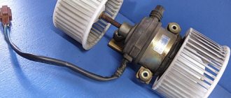
The power of the water pump is not enough to effectively pump antifreeze through the heater radiator. Many “Kulibins” install an additional electric pump on the outlet pipe, which increases the efficiency of the stove. We'll talk about this further.
Principle of operation
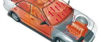
Ventilation system Daewoo Nexia is a supply and exhaust type. The most effective heating of the passenger compartment occurs when the engine is warm.
An air intake is located in front of the windshield of the car, which, when the car is moving, captures the air flow and directs it through a system of ducts and ventilation nozzles into the cabin.
The air movement pattern is shown below.
When parked or when there is insufficient air pressure, the fan turns on.
The heating and ventilation system can operate independently of the air conditioning system. The air entering the cabin is heated using a heat exchanger (radiator).
The movement of the dampers, which direct air flows, is controlled by two actuators (vacuum units) and a hose system. The vacuum unit is structurally equipped with a rod that is attached to the damper.
When switching blowing modes on the control panel, a vacuum is created in a certain nozzle and the rod is retracted and the damper opens or closes.
In the absence of vacuum, the rod moves back under the action of a spring. The flaps are also spring-loaded.
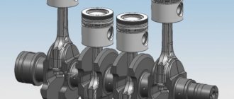
Engine device
All daewoo nexia engines installed on the car were a classic gasoline 4-cylinder, in-line, four-stroke unit. Structurally, the engines were identical, had the same lubrication system, cooling system, and cylinder block. The engine marked G15MF also had a number of significant differences from the Opel Kadett E
The gas distribution system used a scheme with an overhead arrangement of one camshaft. The catalytic converter and lambda probe were missing.
In the newer modification, labeled A15MF, minor design changes were applied. The gas distribution mechanism was driven by two overhead camshafts. The number of valves was increased to 4 per cylinder, and the ignition system was significantly changed. A lambda probe and a catalytic converter were installed on the power plant.
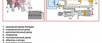
The engine control system consists of an electronic control unit (ECU), sensors for engine and vehicle operating parameters, as well as actuators. The ECU is a special-purpose mini-computer. It consists of random access memory (RAM) and programmable read-only memory (PROM). RAM is used by the microprocessor to temporarily store current information about engine operation (measured parameters) and calculated data. From RAM, the engine control unit takes programs and initial data for processing. Codes of any faults that occur are also recorded in RAM.
The stove heats the air poorly
There may be several reasons for this, but first check whether hot coolant is supplied to the heater.
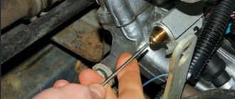
Checking the functionality of the stove
We start and warm up the engine. We turn on the speed mode - 2 or 3. We find two pipes (under the dashboard on the passenger side). The right one supplies hot antifreeze, it enters the radiator from below. The left one is the abductor one, it should not be as hot as the first one.
If the outlet pipe is warm or cold, while the inlet pipe is hot, then the radiator is clogged or there is an air lock in it.
Also turn on recirculation mode and make sure hot air is blowing. In this mode it should heat up very quickly.
Airlock
A common situation after replacing the coolant or when its level is low. To diagnose the problem when the engine is warm, feel the cooling system pipes and find a cold area (relative to others).
The air needs to be expelled. One way is to raise the “face” of the car so that the filler neck of the cooling system is significantly higher than the heater radiator (for example, drive it up a hill or overpass) and let the engine idle for 5-10 minutes, periodically accelerating so that the pump pumps faster antifreeze
Low level of antifreeze in the system
This is clearly determined when the stove heats well at high speeds, but poorly at low speeds. Those. at high speed the pump pumps enough antifreeze, but at low speeds there is not enough coolant to warm up the heater core.
The air temperature regulator damper is slightly open or fully open
The damper is driven by a cable, which could stretch or jump out of the grooves. If it is slightly open, hot and cold air mixes and becomes slightly warm.
For diagnostics, move the throttle lever, which is located below in the area of the knees of the passenger sitting to the left of the driver. Make sure that the cable is not stretched and is intact and in the correct position.
Also check the screw that secures the cable casing; as a result of its loosening, the casing moves and backlash appears, which leads to incomplete closing of the damper. Move the cover towards the interior and tighten the screw.
The heater radiator may also be partially or completely clogged. Read how to clean it in the next section.
A little history of Daewoo Nexia
The ancestor of the Daewoo Nexia car was the well-known Opel Cadet E, which was produced by a German company from 1984 to 1991. At first, Nexia was produced in Korea under the name Daewoo Racer, and its production continued until 1995. For some time, large-scale assembly of the Nexia was carried out in Krasny Askai, Rostov region, but in 1998, production of the car was discontinued.
The main production of Daewoo Nexia was established in Uzbekistan in the city of Asaka, the first cars rolled off the assembly line in 1996. Almost immediately the car began to be exported to Russia, and in 2008 Nexia underwent a slight restyling:
- new headlights appeared;
- bumpers changed;
- the trunk lid has become different;
- The rear lights have been changed.
There were still very minor external changes, but overall the car remained recognizable and differed only slightly from the pre-restyling Nexia.
The first Uzbek Nexias came in two trim levels:
- GL – basic version;
- GLE is the luxury version.
The basic equipment was very simple, sometimes it did not even include power steering. In the GLE version, the car was equipped with additional options:
- electric windows;
- hydraulic power steering;
- air conditioning;
- fog lights;
- electric antenna.
At first, the Daewoo Nexia powertrain lineup included a single 1.5-liter gasoline engine. The engine had a power of 75 hp. pp., in-line arrangement of four cylinders.
The G15MF engine is an 8-valve engine, with one intake and exhaust valve per cylinder; in many ways it is very similar to Opel’s C16NZ internal combustion engine. Despite the apparent external similarity, Opel and Nexia engines have significant differences, and on the G15MF engine:
- the cylinder diameter is different, respectively, the pistons have a completely different configuration and dimensions;
- another casting was made on the crankshaft to drive the oil pump;
- The oil pump itself has a different drive configuration;
- in the cylinder head, instead of a plug at the back, a metal fitting is pressed into place under the cooling system pipe; in addition, the cylinder head has slightly different combustion chambers.
There are also a number of design differences that do not allow the installation of parts from the C16NZ engine on the G15MF engine. In particular, Nexia has its own distributor, and it does not fit any Opel.
The Daewoo Nexia 1.5 engine has the following characteristics:
- fuel system type – distributed injection;
- location on the car – transverse;
- volume – 1498 cm³;
- number of valves – 8;
- cylinder diameter – 76.5 mm;
- piston stroke – 81.5 mm;
- diameter of crankshaft journals – 55 mm;
- diameter of connecting rod journals – 43 mm.
Despite the fact that the Daewoo Nexia 1.5 engine has 8 valves, a car with it can develop quite a decent speed (up to 175 km/h) and accelerate to 100 kilometers in 12.5 seconds. In city mode, fuel consumption with the G15MF engine averages 9.3 liters per 100 kilometers, on the highway outside the city - 7 l/100 km, and during dynamic driving, gasoline consumption increases.
The Nexia 8-valve engine is very reliable, and if you care for it properly (do not overheat, do not overload, change the engine oil on time), then the engine can travel more than 200 thousand kilometers without major repairs. It should be noted that some car owners did not spare the engine in their car at all:
- they poured the cheapest surrogate oil into it;
- forgot to change the oil on time;
- did not check the oil level in the crankcase.
If you remove the oil filler cap from such a “dead” engine, you can immediately see blackness on the camshaft, which is formed from low-quality oil. However, even such motors miraculously survived, and this shows how reliable they are.
In 2002, some changes were made to the Daewoo Nexia, although it is difficult to call them restyling. But the most important novelty of this year is the appearance in the line of power units of a new 16-valve A15MF engine with a volume of 1.5 liters and a power of 85 hp. With.
The main difference between this engine and the 8-valve engine is a completely different cylinder head, in which two camshafts are installed. The power unit no longer has a distributor; the ignition is controlled by an electronic unit. The cylinder diameter remained the same, but the pistons changed - four grooves for the valves appeared on the bottom. To be honest, the grooves on the pistons do not play a special role - if the timing belt breaks, the valves bend. The 8-valve internal combustion engine G15MF remains the winner in this regard; a broken timing belt on it does not cause damage to the engine.
As for the crankshaft, it remains the same; the interchangeability of the A15MF and G15MF crankshafts is complete. Also, the changes did not affect the oil pump, engine sump, flywheel and clutch. Due to the installation of a more advanced ignition system on the Nexia with a 16-valve engine, fuel consumption has decreased slightly:
- in the urban cycle – 9.3 l/100 km;
- on the highway outside the city - 6.5 l/100 km.
Blowing cold
If the stove does not work, i.e. Only cold air flows, then the reasons for this may be the following:
The damper lever (“Cold”, “Heat”) is in the wrong position
Check if you forgot to switch it to the “Cold” position. If the damper is closed, the cabin will be cold even with the fan on.
Heater core clogged
Rinse inside and outside (if necessary). To do this: drain 3 liters of coolant from the engine radiator (do not forget to unscrew the cap of the expansion tank). Remove the hoses from the heater radiator and blow it out on both sides with air under a pressure of at least 3 atmospheres or rinse with clean water (first cold, and therefore hot).
Also use special auto chemicals to flush the system or replace the entire unit. Read here - how to flush the engine cooling system.
If there is a need to replace the pipes, here are their part numbers:
- Return - article number 96179610.
- Supply - article number 96148970.
The thermostat has failed
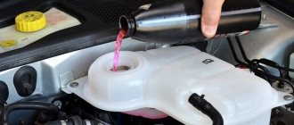
The heating system is designed in such a way that it begins to function immediately after starting the engine (if the heater is on). Those. we started the car, turned on the heater and as the engine warms up, heat will flow into the cabin.
Due to the thermostat valve being in a certain position, antifreeze can constantly move in a large circle. The engine warm-up time increases, the stove will also start working late.
The solution is to replace the thermostat. The standard thermostat on the Daewoo Nexia is 870C. Some people set it to 920C. This increases the time the coolant moves in a small circle, thereby the heater radiator will warm up better.
It is better not to set the thermostat to 970C, since you will have to reflash the ECU.
The damper is stuck in the “Warm” position
In this case, the cable itself can move without jamming. Remove the casing, which is located near the engine (behind the radiator), and not from the passenger compartment, and check how the damper reacts when you try to move it using the lever.
If it is jammed and there is no time or opportunity to fix the problem, turn the damper to the “Cold” position manually and lock it with a self-tapping screw. In the future, you will most likely have to change the stretched cable.
Cabin filter clogged
The Daewoo Nexia has a carbon cabin filter, which is highly hygroscopic.
When it is dirty, the moisture accumulated in it freezes at sub-zero temperatures and the filter does not allow air to pass through. Replace the element, it should help.
Checking the damper for hot and cold air
Warm up the engine and turn it off. We switch the temperature regulator to the leftmost position (blue stripe) and then sharply move it to the far right position (short red stripe).
If the stove damper is working, a characteristic pop will be heard (the damper has closed). If there is no pop, check the “Cold”, “Heat” switch lever. It must go all the way.
If it doesn't reach, shorten the cable.
New engines for 2008
In 2008, in addition to external changes to the body, the Daewoo Nexia updated its engine range:
- Instead of the obsolete G15MF engine, the A15SMS internal combustion engine was installed. This power unit uses a fuel system from Chevrolet Lanos, the engine now meets Euro-3 environmental standards;
- The 16 valve A15MF 1.5 liter engine was replaced by a new internal combustion engine model F16D3, with a volume of 1.6 liters.
The A15SMS engine has become “stronger” than its predecessor, its power has increased to 89 hp. s., but it also has one “fat” minus - due to the fact that the cylinder head of the new engine is installed from a Lanos, if the timing belt breaks, the valves now “meet” the pistons.
Since 2008, the Daewoo Nexia has been equipped with a new 16-valve F16D3 engine that meets Euro 3 and 4 environmental requirements; this engine first appeared on the Chevrolet Lacetti. The Chevrolet Cruze model was also equipped with the F16D3 engine; the prototype of the engine was the Opel X14XE power unit. Although the volumes of these engines are different, structurally and externally they are very similar to each other. Both engines have:
- timing belt drive;
- hydraulic compensators;
- two camshafts;
- exhaust gas recirculation system.
The F16D3 gasoline engine has the following technical characteristics:
- number/location of cylinders – four, in-line;
- volume – 1598 cm³;
- power – 109 hp;
- fuel system - distributed injection;
- compression ratio in cylinders – 9.5;
- cylinder diameter – 79 mm;
- piston stroke – 81.5 mm.
To reduce the toxicity of exhaust gases, an EGR valve is installed on this engine, but the recirculation system often becomes coked from Russian gasoline, and many car owners turn off this valve. The F16D3 engine is not only similar to the X14XE, it also adopted all the diseases from the Opel power unit:
- rapid failure of the lambda probe (also due to low-quality fuel);
- oil leak from the valve cover;
- problems with the thermostat opening earlier than it should.
The leak would not cause much trouble if the oil did not flow into the spark plug wells. Penetrating into the well, the oil hits the electrodes of the spark plug, and the internal combustion engine begins to throttle. But the Daewoo Nexia 1.6 engine rarely consumes oil through the piston rings; in this regard, the engine is reliable.
Like any other car, Daewoo Nexia needs maintenance, and the engine oil must be changed according to the established regulations. The frequency of oil changes on Nexia engines is generally the same as on other passenger car models - every 10 thousand kilometers. If operating conditions are severe (high loads, work in hot climates), it is recommended to change the oil after 5 thousand km.
The requirements for engine oils on the Nexia are standard; no special conditions are imposed on them. To prevent the oil from burning and blackness forming on the parts inside the engine, it must be of high quality, with good additives. It is not recommended to pour mineral oil into engines; it is better to use “synthetic” or “semi-synthetic”.
For winter motor oil, the viscosity should be lower; according to the SAE classification, for frosty winters it is good to use brands 5W30, 0W30, 5W40, 0W40. When starting in cold weather, thick motor oil causes intense wear of engine parts and reduces engine life, so all-season oil should not be used for internal combustion engines in winter.
It is recommended to fill in almost any oil from well-known world manufacturers, the main thing is that it is not a fake. Oil from the following companies is often used in Daewoo Nexia engines:
- Castrol;
- Mobil;
- Chevron;
It has long been proven that it is counterfeit oil that causes the formation of soot and a reduction in engine life. The secret here is very simple - the fake does not contain those high-quality additives that have the necessary lubricating properties and reduce friction between rubbing parts.
If “synthetics” turn out to be too expensive for the car owner, you can replace it with semi-synthetic oil, no big trouble will happen. But when replacing synthetic oil with “semi-synthetic”, it is necessary to thoroughly flush the oil system before pouring new oil into the Daewoo Nexia engine.
The F16D3 engine began to be installed on the Nexia after 2008. Nexia with this engine has become very dynamic, because the engine has a volume of 1.6 and 16 valves. In Daewoo this engine is called DOHC.
Initially, the engine was labeled F14D3 with a volume of only 1.4 liters. After modernization at the GM plant, the “F16D3” engine and its subsequent modifications were born. In turn, the F14D3 is a continuation of Opel’s Z16XE engine (2001), everything is interchangeable with this engine. The next and last modification of the F16D4 engine - phase regulators were added to it and boosted; it has a volume of 125 horsepower versus 109 horsepower on its predecessor.
The stove does not work, 4 and other speeds do not turn on
In this case, the symptoms of a non-working stove are as follows:
- It blows cold - we wrote about this above.
- The fan, or rather the electric motor, does not work.
- The fan turns on and off, and the entire ventilation unit does not work.
- Problems in the control panel.
If there are problems with the electric motor, then the following is possible:
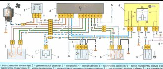
- The fuse (F12 in the diagram) or the heater fan relay (K24 in the diagram below) has blown - replace the fuse and relay.
- There is no power coming to the stove block. There may be problems in the circuit before or in the unit itself, the fuse has blown, you may have to remove it.
- The electric motor burned out and the fan does not work at all 4 speeds. In this case, the air conditioning and recirculation may not work.
Electrical diagram.
Problem solving:
- If the drive is very cold, you can temporarily run a separate wire directly from the ignition switch contact group through the fuse to the fan. You will definitely drive through the winter in a warm car, and in the spring you will figure it out.
- If only fan speed 4 does not work, check the relay for serviceability (the contacts may burn out) and replace it if necessary.
- If the first three speeds do not work, then they are turned on through the resistor block R10 of the heater fan (diagram above), which is located in the air intake housing.
- If the fan periodically turns off and on, and this also happens to the entire ventilation unit, then pay attention to the contact group of the ignition switch (IG). The air conditioner and fan motor are powered through a 15A contact. Check the contacts in the ignition switch CG, replace it if necessary. This solves the problem.
Timing drive of Nexia 1.5 l engine.
The camshaft of the Nexia's 8-valve engine is driven by a toothed belt from the crankshaft. The valves are actuated by the camshaft cams through pressure levers, which rest on the hydraulic lash compensators with one shoulder, and on the valve stems with the other shoulder through guide washers. The engine has hydraulic compensators , which are self-adjusting supports for the pressure levers. Under the influence of oil filling the internal cavity of the compensator under pressure, the compensator plunger selects a gap in the valve drive. The use of hydraulic compensators in the valve drive reduces the noise of the gas distribution mechanism and also eliminates its maintenance.
If the belt breaks, the valve bends! Among other features, it can be noted that the timing belt rotates the pump (water pump). The belt is replaced every 60 thousand kilometers, the pump must be changed every 120 thousand kilometers. Please note that on the old 8-valve engine with 75 hp. The timing belt generally changes every 40 thousand kilometers.
Engine characteristics Nexia 8 valves 80 hp
- Working volume – 1498 cm3
- Number of cylinders – 4
- Number of valves – 8
- Cylinder diameter – 76.5 mm
- Piston stroke – 81.5 mm
- Timing drive - belt
- Power hp – 80 at 5600 rpm. per minute
- Torque – 123 Nm at 3200 rpm. per minute
- Maximum speed – 175 km/h
- Acceleration to the first hundred – 12.5 seconds
- Fuel type – gasoline AI-92
- Fuel consumption in the city – 8.5 liters
- Fuel consumption in the combined cycle – 8 liters
- Fuel consumption on the highway – 7.7 liters
A fairly reliable and unpretentious engine, the main thing is to change the oil, timing belt, and pump on time. A completely repairable power unit. The best option for a budget car.
Source
Location of heater fuses
The electrical component is a common cause of non-functioning of the Daewoo Nexia stove, so it is important to know where the fuses are located, which are responsible not only for its operation, but also for the operation of other systems (air conditioning and ventilation).
The block itself is located in the cabin below to the left of the steering wheel and is divided into two parts: upper (front) and lower (reverse).
Fuse and relay layouts for both parts are shown below.
Technical characteristics of the F16D3 engine from Daewoo Nexia
The approximate engine life is 220 - 250 thousand kilometers. In fact, this motor is considered one of the million-dollar engines; it all depends on the maintenance of the motor, as well as on its operating conditions.
It is worth noting that if the timing belt breaks on this engine, the valves will bend. When a valve breaks, the pistons collide and the higher the crankshaft speed at this moment, the greater the damage.
The engine is installed - Chevrolet Cruze, Daewoo Lanos, Chevrolet Lanos, Daewoo Nexia, Chevrolet Aveo, Chevrolet Lacetti, Daewoo Lacetti, ZAZ Chance, Chevrolet Nexia. A power of 109 horsepower very quickly accelerates such a light car as the Daewoo Nexia.
The Daewoo Nexia stove works, but does not direct air to the legs
If, when the stove is running and the corresponding mode is turned on on the panel, the air is not directed to the legs or its flow is very weak, then first check the sealing of the casing.
We seal all the cracks
Again, there is a design flaw in the heating system of the Daewoo Nexia - there are many cracks through which either cold air is driven, or hot air goes in the wrong place, when it is necessary as a result of the deflection of weak plastic.
The picture below shows that with a strong air flow, the plastic bends, cracks form and hot air goes up and not into the legs.
The problem is solved by eliminating the cracks: using self-tapping screws, seals and double-sided tape. Make sure there are no gaps at all.
Vacuum actuators are faulty
Next, pay attention to the vacuum actuators (there are two of them) with the help of which (through levers and a system of pipes) three dampers for the direction of air flows are controlled: blowing the windows - the face, the legs, the face.
Switching is done on the instrument panel.
The vacuum seals may be faulty. To check this, dismantle them. This is not difficult to do - pull them off the mount and spread out the rod that is attached to the damper. Disconnect the hose.
Next, retract the rod and pinch the inlet hole with your finger. If the rod does not return to its original position, then the vacuum seal is working; if it returns, it is faulty (the membrane is torn) and requires replacement.
Properly connected pipes also play an important role, since each of them plays its own role.
There are situations, after purchasing a Daewoo Nexia on the secondary market, when, for example, a black pipe is confused with a black one with an orange stripe, etc., which leads to an incorrect response of the dampers (the “Legs” mode is turned on, but it blows in the face, and vice versa ).
Below is a diagram of the vacuum connections and what function each of the pipes performs.
It is also important to know how the system operates when one mode or another is turned on.
Foot airflow:
- A vacuum is created in the hose with red stripes, while the orange one is not used. The “Head” vacuum valve rod (see photo above) is retracted, blocking the air flow to the face.
- A vacuum is created in the pipe with blue stripes. The “Glass/legs” vacuum valve rod is fully extended – 100% of the hot air goes to the legs, and it is blocked off to the glass.
Blows in the face:
- The rod of the vacuum valve, which is responsible for blowing the head, is fully extended, while a vacuum is supplied through the black hose with orange stripes, and the hose with red stripes is not used.
- Vacuum unit "Glass/legs". The pipe with blue stripes is not used. The rod is pushed out completely under the action of the spring - 100% blows on the glass.
Blows on the face and feet:
- A vacuum is created in the nozzles with orange and red stripes. The “HEAD” actuator rod is extended halfway. There is uniform airflow to the face and legs.
- A vacuum is created in the hose with blue stripes. The glass/legs actuator rod is extended. Only the legs are blown.
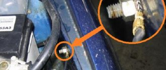
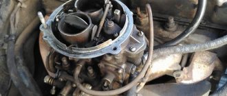
Open the hood. Find the pneumatic chamber, which is located near the cabin filter and check the condition of the two pipes:
- The black and white comes from the pneumatic chamber on the PUP (vacuum is taken from it, and it can jump off under the hood or in the area of connection to the control panel).
- Transparent yellow - from the intake manifold.
Next, we check the fastening of the vacuum seals; they often break - this is again a design flaw of the engineers.
If the dampers open normally, then the counterforce on the rods is moderate and the load on the fasteners is acceptable so that they do not break.
But over time and with frequent use of blowing modes, the resistance of the powerful damper springs on the rod and fastening leads to the fact that the latter loses its rigidity and does not hold the vacuum seal. He flies off.
Also, for some reason, the damper may become jammed, and it moves with difficulty or does not close completely (debris has entered). In this situation, when the rod moves, the counterforce on it increases, and accordingly, on the fastening too.
In the best case, the vacuum seal will jump out of its normal place, but often the fastening breaks, the rod becomes warped and cannot open the valve.
Therefore, many owners of the Daewoo Nexia will improve the design of the actuator mounting, making it metal and fastening it with bogs.
Below is a solution to the problem.
If the mount begins to bend strongly when switching modes, some car owners get out of the situation by making an ellipse-shaped hole in the area where the damper axis enters the rod in the direction of movement of the damper. There is some play at the rod, thereby reducing the load on the fastening itself, and it bends less.
Problem in the control unit
The vacuum pipes are connected to a special device in the control unit, through which the vacuum is redirected.
If there is hissing, poor opening and closing of the dampers, this may be the problem.
You will have to remove the control unit (how to do this is described below).
When the unit is removed, you need to remove the cover of the device as shown below.
To do this, unscrew a small screw - be careful, the lid is spring-loaded.
Next we see an elastic band that is offset relative to the axis - this is the “problem”. It must be clearly centered relative to the axis.
Carefully pry it up, apply glue and fix it back (there is a special groove there that will prevent installation mistakes).
It is better to use glue that does not dry quickly. Adhesives such as “Second”, “Superglue”, etc. in our case they are not suitable, since it is very important to center the elastic band, and it is unlikely to be possible to do this right away. Incorrect fixation of the elastic band and change the entire unit as this is not sold separately. Or you will have to look for such a block at disassembly.
Understanding the Daewoo Nexia box
The most common remains the five-speed manual gearbox - a prototype developed by Opel. The oil in it should be changed every 80–90 thousand km, although the manufacturer does not mention this procedure; car owners and mechanics advise adhering to such regulations.
Over time, the main gear oil seal begins to leak, and on used cars the smoothness of shifting is often disrupted. To make gear shifting easier, change the drive rods and bushings (sold as a set). Additionally, the box can be treated with a friction geomodifier. This will restore the geometry of the gears, reduce the noise level and the amount of vibration, which is useful for transmissions of new and used Daewoo Nexia. in the gearbox, RVS-Master compensates for wear and forms a protective layer, and not a temporary film, unlike its competitors, which allows you to carry out repairs yourself without disassembling the gearbox and get rid of the hum.
Engine Nexia 8 valves
1.5 liter capacity has become one of the most popular on Daewoo Nexia in recent years. Today there are quite a few cars on the secondary market with this engine. 80 hp unit (A15 SMS), this is a naturally aspirated gasoline engine with distributed multipoint fuel injection with an ignition coil, which replaced the 1.5-liter G15 MF engine developing 75 hp. with an unreliable distributor.
Removing the control unit
To remove the control unit, do the following:
- Remove the decorative panel around the entire control unit. It is attached with clamps in a circle. Carefully pry it around the perimeter with a thin screwdriver or a bank card.
- Using a screwdriver, pry and unclip the control unit from the top and bottom and pull it half a centimeter towards you.
- Disconnect the cable coming from the block. It is located in the area of the front passenger's left leg. To do this you need a Phillips screwdriver. We unscrew the self-tapping screw and move the cable to the right.
- Disconnect the block with wires by unclipping the connector as shown below.
- We pull out the block even more and disconnect another block with wires.
- We pull out the block together with the cable, while the vacuum redistribution block along the pipes may remain in place or you will have to disconnect it by pressing two latches
- To pull out the entire panel, remove the plastic clip located in the back, as shown below.
Now you can work with the unit itself - disassemble, repair or replace.
Daewoo Nexia | Access to the engine compartment
Access to the engine compartment
| The hood release lever handle is located on the left under the vehicle's instrument panel. When you pull the handle toward you, the hood should lift slightly. |
| After releasing the lock latch, exit the passenger compartment and walk around the front of the car. The release tongue of the additional hood latch latch should move slightly out of the decorative radiator grille; pull it towards you. |
Before lifting the hood, make sure that the windshield wiper arm is not tilted forward.
Before slamming the hood, make sure that you have not left any tools, rags or other foreign objects in the engine compartment. To close, lower the hood to the bottom position, leaving a gap of about 10 centimeters, then release it. To check that the hood is securely locked in the closed position, pull it up by the front edge.
| To avoid damaging the paintwork, you should not press the hood when it is not tightly closed with your hands; the correct thing to do is to open it again and try to slam it again and release it from a small height. |
automn.ru
Adjusting the heater dampers
To adjust the heater dampers:
- Completely remove the control unit.
- Get to the radiator.
- Without touching the wiring, unscrew the three radiator mounting bolts using a size 7 ratchet and move it down.
- Having reached the damper, turn it all the way to different positions and check for gaps. If they are, then use a sealant or other method to eliminate them.
- Adjust the damper cable by tightening or loosening it.
Daewoo Nexia | Access to the engine compartment
Access to the engine compartment
| 1. The hood latch release handle is located on the left under the vehicle's instrument panel. To release the latch when unlocking the hood, pull the handle towards you. |
| 2. To open the hood after releasing the latch, the safety lock must be removed. The lock release lever is located under the decorative radiator grille, in the center - pull it to the left. |
| 3. To fix the hood in the open position, a stop rod is provided, which is tucked into a special groove on the underside of the cover. Before closing the hood, make sure that the support rod is securely fixed in its holder. |
4. To close, lower the hood to the bottom position, leaving a gap of about 10 centimeters, then release it. To check that the hood is securely locked in the closed position, pull it up by the front edge.
| To avoid damaging the paintwork, you should not press the hood when it is not tightly closed with your hands; the correct thing to do is to open it again and try to slam it again and release it from a small height. |
automn.ru
Modification of the stove to improve its efficiency
The essence of the modification is to minimize heat loss by antifreeze. To do this, run the coolant according to a scheme that provides for the exclusion of the expansion tank. Those. The return must be connected directly to the filler pipe. This is realized through a tee.
Procedure:
- We cut the return hose at a distance of 5-6 cm from the expansion barrel (RB).
- From the RB side, plug the hose using a bolt and clamp.
- At a distance of 6-8 cm from the RB, we cut off the inlet hose, retreat 4-5 cm and cut it again, thereby shortening it.
- We connect the newly cut hose to the tee on both sides, and connect the return line to the third.
The advantage of this design is that:
- Antifreeze starts working again with minimal temperature loss.
- Bubbles are not created in the expansion barrel (many people suspect that they are the cause of air locks).
- It is easier to remove air from the system.
At the same time, the opportunity to monitor the coolant level is not lost, and the valve cover RB continues to perform its functions of monitoring pressure in the system.
Engines
Nexia buyers can choose from two engines. The 1.5-liter eight-valve engine (80 hp) is accompanied by a relatively modern 16-valve engine with a volume of 1.6 liters and a power of 109 hp. Both comply with Euro 3 standards and are not fast. This is especially true for the 1.5-liter unit.
Motors are oil eaters. However, this largely depends on operating conditions and driving style. Consumption of 300 g per thousand km is considered normal for them. Under our operating conditions, it is better not to forget about the oil level in the intervals between scheduled service visits. Speaking of maintenance. In 2010, new maintenance regulations were developed. Previously, the so-called zero maintenance had to be completed after a thousand kilometers, but now the service interval has increased to two thousand. Scheduled maintenance visits are required to be made at intervals of 10 thousand kilometers or once a year, and not every six months, as was previously the case. Violation of service rules leads to loss of warranty, in fact, like with any automaker.
Note that, according to the new regulations, the warranty for Nexia is 3 years or 100 thousand km.
Maintenance is prescribed scrupulously and quite extensively. Thus, TO-3 (20 thousand kilometers) involves changing the oil, air and fuel filters, and spark plugs. Together with original components, a service visit will cost about 8 thousand rubles. (work - up to 2 thousand rubles, parts - about 6 thousand rubles). A little expensive, of course, but under the hood they will update you with a lot of things.
The timing kit on both engines is changed every 40 thousand kilometers (TO-5). On an eight-valve engine, a tensioner pulley is included with the belt. The timing structure of a 1.6-liter engine with 16 valves is more complex. In addition to the belt, it includes an automatic tensioner roller and a support roller.
The “sweating” of the 1.5-liter engine is the talk of the town! Oil regularly leaks from under the valve cover and cylinder head gaskets. Replacing the gaskets helps for a couple of thousand km at best. One way to eliminate “excess” oil is to install a valve cover from a Chevrolet Lanos. Another is washing the engine at every service. The procedure will cost 300 rubles, but under the hood it will always be clean.