Dear readers and subscribers, it’s nice that you continue to study the structure of cars! And now we bring to your attention the electronic fuel injection system, the operating principle of which I will try to explain in this article.
Yes, we’ll talk about those devices that have replaced time-tested carburetor power systems from under the hoods of cars, and we’ll also find out how much modern gasoline and diesel engines have in common.
Carburetor power systems
Let us first consider carburetor power systems, which were widespread until recently. They are simpler and cheaper than injection ones, do not require highly qualified maintenance during operation, and in some cases are more reliable.
The fuel supply system for a carburetor engine includes a fuel tank 1, coarse 2 and fine 4 fuel filters, fuel pump 3, carburetor 5, intake pipe 7 and fuel lines. When the engine is running, fuel from tank 1 is supplied via pump 3 through filters 2 and 4 to the carburetor. There it is mixed in a certain proportion with air coming from the atmosphere through the air cleaner 6. The combustible mixture formed in the carburetor enters the engine cylinders through the intake manifold 7.
Fuel tanks in power plants with carburetor engines are similar to the tanks of diesel power systems. The only difference between gasoline tanks is their better sealing, which prevents gasoline from leaking even when the vehicle overturns. To communicate with the atmosphere, two valves are usually installed in the filler cap of the tank - inlet and outlet. The first of them ensures that air enters the tank as fuel is consumed, and the second, loaded with a stronger spring, is designed to communicate the tank with the atmosphere when the pressure in it is higher than atmospheric (for example, at high ambient temperatures).
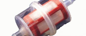
Filters for carburetor engines are similar to those used in diesel power systems. Plate-slot and mesh filters are installed on trucks. For fine cleaning, cardboard and porous ceramic elements are used. In addition to special filters, individual units of the system have additional filter meshes.
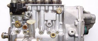
The fuel priming pump is used to force gasoline from the tank into the carburetor float chamber. On carburetor engines, a diaphragm-type pump driven by a camshaft eccentric is usually used.
Depending on the operating mode of the engine, the carburetor allows you to prepare a mixture of normal composition (a = 1), as well as lean and enriched mixtures. At low and medium loads, when it is not necessary to develop maximum power, you should prepare it in the carburetor and feed a lean mixture into the cylinders. For heavy loads (their duration of action is usually short), it is necessary to prepare an enriched mixture.
Rice. Diagram of the fuel supply system for a carburetor engine: 1 - fuel tank; 2 — filter with fuel purification pipe; 3 — fuel priming pump; 4 — fine filter; 5 - carburetor; 6 — air cleaner; 7 - intake manifold
In general, the carburetor includes a main metering and starting device, idle and forced idle systems, an economizer, an accelerator pump, a balancing device and a maximum crankshaft speed limiter (for trucks). The carburetor may also contain an econostat and a height corrector.
The main metering device operates in all main engine operating modes in the presence of vacuum in the mixing chamber diffuser. The main components of the device are a mixing chamber with a diffuser, a throttle valve, a float chamber, a fuel nozzle and spray tubes.
The starting device is designed to ensure the start of a cold engine, when the rotation speed of the crankshaft cranked by the starter is low and the vacuum in the diffuser is low. In this case, for a reliable start, it is necessary to supply a highly enriched mixture to the cylinders. The most common starting device is a choke valve installed in the carburetor intake pipe.
The idle system is used to ensure engine operation without load at a low crankshaft speed.
The forced idle system allows you to save fuel while driving in engine braking mode, that is, when the driver, with the gear engaged, releases the accelerator pedal connected to the carburetor throttle valve.
We recommend: Learning to change gears on a manual transmission
The economizer is designed to automatically enrich the mixture when the engine is running at full load. In some types of carburetors, in addition to the economizer, an econostat is used to enrich the mixture. This device supplies additional fuel from the float chamber to the mixing chamber only when there is a significant vacuum in the upper part of the diffuser, which is only possible when the throttle valve is fully open.
The accelerator pump provides forced injection of additional portions of fuel into the mixing chamber when the throttle valve is sharply opened. This improves the throttle response of the engine and, accordingly, the vehicle. If there were no accelerator pump in the carburetor, then with a sharp opening of the damper, when the air flow rate increases rapidly, due to the inertia of the fuel, the mixture would at first become very lean.
The balancing device serves to ensure stable operation of the carburetor. It is a tube connecting the carburetor intake pipe to the air cavity of a sealed (not communicating with the atmosphere) float chamber.
A maximum engine speed limiter is installed on truck carburetors. The most widely used limiter is the pneumatic centrifugal type.
Description of the advantages of injection systems
Compared to carburetors, injection engine power systems have the following advantages:
- More careful dosing of the amount of fuel mixture allows you to significantly save overall consumption.
- The use of sensors that monitor the characteristics of fuel mixtures and exhaust gases leads to a reduction in exhaust toxicity.
- Ignition timing and angle adjustment in accordance with engine modes contribute to an increase in power by almost 10%.
- When the load changes, the injection system instantly adjusts the composition of the fuel-air mixture.
- Guaranteed easy starting in any weather.
- Reducing the amount of hydrocarbons in exhaust gases
Disadvantages of injection engines:
- high prices for repairs and maintenance;
- many components and parts cannot be restored; there is a need to completely replace them;
- increased requirements for gasoline quality;
- the need for specialized diagnostic, maintenance and repair equipment.
What types of injectors are there?
The fuel supply in an injection engine depends decisively on the injectors . For a long time, a mono-injection system was very common, in which all cylinders can be injected through one nozzle. For some time it existed along with multipoint injection.
These types of injectors have evolved in different ways. Single injection did not comply with Euro-3, quickly became outdated and is not common. Today, a more advanced system dominates, with the help of distributed fuel injection .
Here, a separate injector is placed on the cylinder intake manifold, or through it the fuel mixture enters directly into the combustion chamber. Distributed injection of the fuel mixture can be:
- Simultaneous;
- Pair-parallel;
- Phased or sequential.
Cars that have imperfect fuel injection systems require special attention. "Gazelle" is one example of this. Replacing a carburetor engine with an injection engine sometimes did not reduce high fuel consumption.
Main sensors
- Crankshaft position sensor (Hall sensor). Lets the block know the location of the pistons in the cylinders. The essence of the work is that a gear located on the motor shaft moves near a magnet. Its teeth distort the magnetic field, creating pulses in the coil. The ECU reads these pulses and determines the position of the crankshaft. If this sensor fails, then you will not be able to drive your car to the service station.
- Air flow sensor (DRV). There are two types of such sensors, one measures the mass and the other the volume of intake air. The mass air flow sensor takes measurements and sends them to the ECU. There is a heating element in the flow, the temperature of which is automatically kept at the desired level. The heavier the air, the more current must pass through it to maintain the optimal temperature. Therefore, the ECU determines the mass of intake air by current strength. As for the volume sensor (DOVR), it is designed like this. In the flow where the air intake passes, a partition is installed that opens under the pressure of air. The ECU determines the position of the damper using a potentiometer. During a malfunction, the sensor parameters are not taken into account, and the calculation is carried out according to the indicators of the emergency table.
Injector ECU
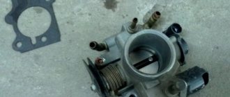
- Throttle position sensor . Controls the position of the throttle valve, due to which the ECU can correctly reduce or increase fuel consumption.
- Oxygen sensors (lambda probe). Calculates the amount of oxygen in exhaust gases. Based on its readings, the ECU detects a lean mixture and makes corrections.
- Coolant temperature sensor . Lets the computer know when the motor has reached the desired operating temperature. At the time of the accident, the sensor parameters are ignored; the temperature is taken from the table based on the engine operating time.
- Manifold absolute pressure sensor (MAP) Analyzes the air and its quantity in the intake manifold; this indicator is needed to determine the amount of energy conducted.
- Voltage sensor . Monitors the voltage of the vehicle's on-board network. Based on its readings, the controller can increase or, conversely, decrease engine idle speed.
- Knock sensor . It is a high-frequency microphone that picks up unacceptable sound vibrations in the motor. Receiving abnormal sounds, the controller automatically adjusts the advance angle.
We recommend: Car suspension: elements, diagram, types
Central fuel injection
More and more cars equipped with microprocessor engine control systems are appearing on our roads. Many people already forget the words “carburetor” and “distributor”, because they have an “injector”.
The domestic automobile industry is trying to catch up with the West by leaps and bounds. At the same time, development does not follow the path of evolution, but is revolutionary. We skip over many stages of development, not knowing the opportunities and advantages that they gave in their time in the West, and what the West sacrificed for the sake of the environment. We immediately moved from the carburetor and distributor to phased microprocessor control systems for distributed fuel injection and ignition. At the same time, we are observing nonsense in the Russian automobile industry. The same plant produces cars that meet EURO-2 environmental requirements, stuffed with the latest electronic systems. And cars equipped with carburetors and contact distributors of the mid-60s model come off the neighboring assembly line. There is no logic in this. There are only economic feasibility and holes in the legislation.
VAZ tried to destroy this practice by starting production of the Niva with a central fuel injection system. Unfortunately, this trend did not spread to the rest of the “classics”. Installation of electronic systems significantly increases the cost of cars. An increase in price reduces the demand for cars, which bring significant profits to the plant. And the low price of the “classic” is the main reason for its popularity. Who would strangle the goose that lays the golden eggs?
But let's return to the history of the emergence of fuel injection systems. First, as an alternative to the carburetor, distributed fuel injection appeared directly into the engine cylinders (evaluate the spiral of history), which came to the car from aviation. But it was expensive, short-lived and unreliable. The distributed fuel injection systems that appeared in the 70s with fuel supplied to the intake valve were cheaper, but the difference with the price of a carburetor was very large. She remains that way today. The main advantage of the multipoint fuel injection system is higher engine power at high speeds.
To achieve these indicators, an original intake system is required, as well as components and assemblies of the distributed fuel injection system. The impact of the cost of the injection system on small cars is especially noticeable.
Then the idea arose to use one instead of several injectors, installing it instead of a carburetor. At the same time, the design of the standard carburetor engine remained virtually unchanged. The United States followed this development path, using a central fuel injection system (CVI) on engines with a displacement of up to 8 liters until the mid-90s. The use of a central fuel injection system made it possible to get rid of many carburetor diseases in the form of clogged jets and difficulty in adjustment.
With the transition from analog electronic systems to digital microprocessor systems, the fuel supply and ignition systems were combined into one control unit.
Let us dwell on the principles of formation of fuel supply and ignition timing in CVT systems. Engine speed is read by a sensor mounted on the crankshaft. The engine load is determined by an absolute pressure sensor installed in the intake pipe after the throttle valve. The combination of these two parameters, speed and load, gives the control unit the entire field of operating loads on the engine, the basic fuel supply surfaces and ignition timing. Fuel supply by an injector, instead of ejection in a diffuser, ensures stable engine operation at low air flow rates, for example, at full throttle and low engine speeds or when starting the engine. The composition of the mixture is regulated by a special potentiometer or assessed using feedback from an L-probe. The idle speed is maintained using the idle speed controller in accordance with the temperature conditions.
The use of an absolute pressure sensor instead of a vacuum sensor allows the control unit to take into account changes in external atmospheric conditions. Changes in the temperature state of the engine and the environment are monitored by coolant and air temperature sensors. The degree of driver input on the throttle pedal (amount of movement, speed and acceleration) is assessed by the throttle position sensor. In addition, the throttle position sensor provides a backup load sensing function in the event of MAP sensor failure. The built-in diagnostic system promptly informs the driver about all malfunctions.
In Russia, since the late 80s, the Dimitrovgrad Automotive Assembly Plant (DAAZ) has been working on the topic of central fuel injection.
Over the past years, their developments have significantly advanced the West. The phased CVT system they created made it possible to get rid of the last carburetor disease - uneven distribution of the mixture among the cylinders. Now each cylinder receives exactly the amount of fuel required to operate in a given mode. As a result, the fuel consumption of a car with CVT is the same as with distributed fuel injection.
But let's return to Russian car manufacturers. The Gorky Automobile Plant equips more than half of its cars with a ZMZ-402 engine. This engine has not been modernized since the early 80s. The use of distributed fuel injection on it significantly increases the cost of the engine, making it comparable in price to the ZMZ-4062. The possibility of using central fuel injection was never seriously considered by ZMZ management. At this stage, the Zavolzhsky Motor Plant is interested in stopping the production of ZMZ-402 and reconfiguring the vacant production facilities for the production of ZMZ-4062.
But the 402nd family of engines is very familiar in use; its repair is possible in any garage. It is not picky about the quality of gasoline and oil. Installation of TsVT equipment on the ZMZ-402 allows the vehicle to be equal in efficiency to the ZMZ-4062 engine, in some modes and surpass it. So, when conducting evaluation tests on a car with a ZMZ-4021 engine (A-76 gasoline) in urban conditions, fuel consumption was 10.1 l/100 km. At a steady state driving speed of 90 km/h in 5th gear, fuel consumption was 7.8 l/100 km. Acceleration in 5th gear is possible from a speed of 25 km/h (300 engine revolutions per minute). Confident engine start - at -26 degrees. C" at the 6th second when the battery is 60% charged. The starting engine speed was 45 rpm. Semi-synthetic motor oil 5W-40.
The ignition distributor is removed from the vehicle. Instead, a 4-pin Bosch ignition coil with static high-voltage voltage distribution is installed. The high-voltage discharge is supplied to the spark plugs via silicone high-voltage wires with silicone tips. This protection allows you to work under water, reliably insulating the candle.
The use of a central fuel system and microprocessor ignition will relieve you of all the problems and hassles associated with frequent adjustment of mechanical moving systems. Will give your car new qualities.
A. Adyasov Photo NetRaider
Brief history of appearance
The fuel injection system began to be actively introduced in the 70s, as a response to the increased level of emissions of pollutants into the atmosphere. It was borrowed from the aircraft industry and was an environmentally safer alternative to a carburetor engine. The latter was equipped with a mechanical fuel supply system, in which fuel entered the combustion chamber due to a pressure difference.
The first injection system was almost entirely mechanical and was characterized by low efficiency. The reason for this was the insufficient level of technological progress, which could not fully reveal its potential. The situation changed in the late 90s with the development of electronic engine control systems. The electronic control unit began to control the amount of fuel injected into the cylinders and the percentage of components of the air-fuel mixture.
The essence of the direct injection scheme into the combustion chamber
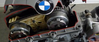
For a person who does not have a technical mind, understanding this issue is an extremely difficult task. But still, knowledge of the differences between this engine modification and an injection or carburetor modification is necessary. For the first time, engines with direct injection were used in the 1954 Mercedes-Benz model, but this modification gained great popularity thanks to the Mitsubishi company under the name Gasoline Direct Injection.
And since then, this design has been used by many well-known brands, such as:
- BMW,
- Infinity,
- Ford
- General Motors,
- Hyundai
- Mercedes-Benz
- Mazda.
In this case, each of the companies uses its own name for the system in question. But the principle of operation remains the same.
The growing popularity of the fuel injection system is facilitated by its efficiency and environmental friendliness, since its use significantly reduces the emission of harmful substances into the atmosphere.
Fuel injection systems
Fuel injection systems are currently used much more often than carburetor systems, especially on gasoline engines of passenger cars. Gasoline is injected into the intake manifold of an injection engine using special electromagnetic injectors (injectors) installed in the cylinder head and controlled by a signal from the electronic unit. This eliminates the need for a carburetor, since the combustible mixture is formed directly in the intake manifold.
There are single-point and multi-point injection systems. In the first case, only one injector is used to supply fuel (with its help, the working mixture is prepared for all engine cylinders). In the second case, the number of injectors corresponds to the number of engine cylinders. The injectors are installed in close proximity to the intake valves. The fuel is injected in a fine spray onto the outer surfaces of the valve heads. Atmospheric air, entrained into the cylinders due to rarefaction in them during intake, washes fuel particles from the valve heads and promotes their evaporation. Thus, the air-fuel mixture is prepared directly at each cylinder.
In an engine with multipoint injection, when power is supplied to the electric fuel pump 7 through the ignition switch 6, gasoline from the fuel tank 8 through filter 5 is supplied to fuel rail 1 (injector rail), common to all electromagnetic injectors. The pressure in this ramp is regulated using regulator 3, which, depending on the vacuum in the inlet pipe 4 of the engine, directs part of the fuel from the ramp back to the tank. It is clear that all injectors are under the same pressure, equal to the fuel pressure in the rail.
When it is necessary to supply (inject) fuel, an electric current is supplied to the winding of the electromagnet of injector 2 from the electronic unit of the injection system for a strictly defined period of time. The electromagnet core, connected to the injector needle, is retracted, opening the way for fuel into the intake manifold. The duration of the electrical current supply, i.e. the duration of fuel injection, is regulated by the electronic unit. The electronic unit program at each engine operating mode ensures optimal fuel supply to the cylinders.
Rice. Diagram of the fuel supply system for a gasoline engine with multipoint injection: 1 - fuel rail; 2 — nozzles; 3 - pressure regulator; 4 — engine inlet pipe; 5 - filter; 6 — ignition switch; 7 - fuel pump; 8 - fuel tank
In order to identify the engine operating mode and calculate the injection duration in accordance with it, signals from various sensors are sent to the electronic unit. They measure and convert the following engine operating parameters into electrical impulses:
- throttle angle
- degree of vacuum in the intake manifold
- crankshaft speed
- intake air and coolant temperature
- oxygen concentration in exhaust gases
- Atmosphere pressure
- battery voltage
- and etc.
Engines with gasoline injection into the intake manifold have a number of undeniable advantages over carburetor engines:
- fuel is distributed more evenly among the cylinders, which increases engine efficiency and reduces engine vibration; due to the absence of a carburetor, the resistance of the intake system is reduced and cylinder filling is improved
- it becomes possible to slightly increase the degree of compression of the working mixture, since its composition in the cylinders is more homogeneous
- optimal correction of the mixture composition is achieved when switching from one mode to another
- provides better engine response
- exhaust gases contain less harmful substances
We recommend: Your actions in case of an accident
However, power systems with gasoline injection into the intake manifold have a number of disadvantages. They are complex and therefore relatively expensive. Servicing such systems requires special diagnostic instruments and devices.
The most promising fuel supply system for gasoline engines is currently considered to be a rather complex system with direct injection of gasoline into the combustion chamber, which allows the engine to operate for a long time on a very lean mixture, which increases its efficiency and environmental performance. At the same time, due to the existence of a number of problems, direct injection systems have not yet become widespread.
Types of injection systems for gasoline engines
There are several main types of fuel injection systems, which differ in the way the air-fuel mixture is formed.
Single injection or central injection
Scheme of operation of the mono-injection system
The scheme with central injection provides for the presence of one nozzle, which is located in the intake manifold. Such injection systems can only be found on older passenger cars. It consists of the following elements:
- Pressure regulator – ensures a constant operating pressure of 0.1 MPa and prevents the appearance of air locks in the fuel system.
- Injection nozzle - pulses gasoline into the engine intake manifold.
- Throttle valve - regulates the volume of supplied air. May have a mechanical or electric drive.
- Control unit - consists of a microprocessor and a memory unit, which contains reference data for fuel injection characteristics.
- Sensors for engine crankshaft position, throttle position, temperature, etc.
Gasoline injection systems with one injector operate according to the following scheme:
- The engine is running.
- Sensors read and transmit information about the state of the system to the control unit.
- The obtained data is compared with the reference characteristic, and, based on this information, the control unit calculates the moment and duration of opening the nozzle.
- A signal is sent to the electromagnetic coil to open the injector, which leads to the supply of fuel to the intake manifold, where it is mixed with air.
- A mixture of fuel and air is supplied to the cylinders.
Multiport injection (MPI)
A distributed injection system consists of similar elements, but in this design there are separate injectors for each cylinder, which can open simultaneously, in pairs or one at a time. Mixing of air and gasoline also occurs in the intake manifold, but, unlike single injection, fuel is supplied only to the intake tracts of the corresponding cylinders.
Diagram of operation of a system with distributed injection
The control is carried out electronically (KE-Jetronic, L-Jetronic). These are universal Bosch fuel injection systems that are widely used.
Operating principle of distributed injection:
- Air is supplied to the engine.
- Using a number of sensors, the volume of air, its temperature, the speed of rotation of the crankshaft, as well as the throttle position parameters are determined.
- Based on the data received, the electronic control unit determines the volume of fuel that is optimal for the amount of air supplied.
- A signal is given and the corresponding injectors open for the required period of time.
Direct fuel injection (GDI)
The system provides for the supply of gasoline through separate injectors directly into the combustion chambers of each cylinder under high pressure, where air is simultaneously supplied. This injection system provides the most accurate concentration of the air-fuel mixture, regardless of engine operating mode. In this case, the mixture burns almost completely, thereby reducing the volume of harmful emissions into the atmosphere.
Direct injection system operation diagram
This injection system is complex in design and sensitive to fuel quality, making it expensive to manufacture and operate. Since the injectors operate in more aggressive conditions, for the correct operation of such a system it is necessary to ensure high fuel pressure, which must be at least 5 MPa.
Structurally, the direct injection system includes:
- High pressure fuel pump.
- Fuel pressure control.
- Fuel rail.
- Safety valve (installed on the fuel rail to protect system elements from pressure increases above the permissible level).
- High pressure sensor.
- Injectors.
An electronic injection system of this type from Bosch is called MED-Motronic. The principle of its operation depends on the type of mixture formation:
- Layer-by-layer – implemented at low and medium engine speeds. Air is supplied to the combustion chamber at high speed. Fuel is injected towards the spark plug and, mixing with air along the way, ignites.
- Stoichiometric. When you press the gas pedal, the throttle valve opens and fuel is injected simultaneously with the air supply, after which the mixture ignites and burns completely.
- Homogeneous. Intensive air movement is provoked in the cylinders, while gasoline is injected during the intake stroke.
Direct fuel injection in a gasoline engine is the most promising direction in the evolution of injection systems. It was first implemented in 1996 on Mitsubishi Galant passenger cars, and today most major automakers install it on their cars.
Features of the injection engine design
In order to competently operate a car that has a power supply system for a gasoline engine with fuel injection , you need to have an understanding of its operation. Especially when it comes to domestic cars, the fuel injection system of the VAZ 2114 and other cars.
Without this, it will be difficult to understand and eliminate possible machine malfunctions yourself. Having mastered the design features, the operating principle, and the structure of the injection engine, you can understand the malfunction and even eliminate it without going to a service station.
The injection engine is controlled by a controller. In domestic cars it is usually placed on the right under the dashboard. The task of this device is to continuously process information about the state of the motor and ensure reliable operation of its systems. The control unit includes various relays, injectors, and sensors.
Using the built-in diagnostic system, a problem in the engine is recognized, signaling with a warning lamp, and stores diagnostic fault codes. It has three storage devices that allow you to quickly analyze the technical condition over different periods of time.
A fundamental feature of the engine is the presence of injectors that provide dosed injection of the air-fuel mixture into the intake pipe after receiving a command from the control unit. In this case, the necessary air is supplied using the throttle unit and the idle speed regulator. The injectors are attached to a ramp, which is mounted on the intake pipe.
The nozzle is an electromechanical valve, which is closed by a needle using a spring. When a pulse is supplied from the control unit to the winding of the injector electromagnet, the needle rises, opening the spray nozzle. Through it, the mixture is supplied to the engine intake pipe. Injectors require constant monitoring. The slightest clogging of them can negatively affect the operation of the engine.
Also an important part of this engine is the converter, which converts harmful components of exhaust gases.
Design and principle of operation of the injection injection system
The second name for injection systems in gasoline engines is injection. Its main feature is the precise dosage of fuel. This is achieved by using nozzles in the design. The engine injection device includes two components - executive and control.
The task of the executive part is to supply gasoline and spray it. It does not include many components:
- Tank.
- Pump (electric).
- Filter element (fine filter).
- Fuel lines.
- Ramp.
- Injectors.
But these are only the main components. The executive component may include a number of additional components and parts - a pressure regulator, a system for draining excess gasoline, an adsorber.
The task of these elements is to prepare the fuel and ensure its flow to the injectors, which are used to inject them.
The operating principle of the executive component is simple. When you turn the ignition key (on some models - when you open the driver's door), the electric pump turns on, which pumps gasoline and fills the remaining elements with it. The fuel is cleaned and flows through fuel lines into a ramp that connects the injectors. Due to the pump, the fuel in the entire system is under pressure. But its value is lower than on diesel engines.
The opening of the injectors is carried out due to electrical impulses supplied from the control part. This component of the fuel injection system consists of a control unit and a whole set of tracking devices - sensors.
These sensors monitor indicators and operating parameters - crankshaft rotation speed, amount of air supplied, coolant temperature, throttle position. The readings are sent to the control unit (ECU). He compares this information with the data stored in memory, on the basis of which the length of the electrical pulses supplied to the injectors is determined.
The electronics used in the control part of the fuel injection system are needed to calculate the time for which the injector should open in a particular operating mode of the power unit.
Types of injectors
But note that this is the general design of the supply system of a gasoline engine. But several injectors have been developed, and each of them has its own design and operating features.
Engine injection systems are used on cars:
- central;
- distributed;
- direct.
Central injection is considered the first injector. Its peculiarity is the use of only one injector, which injected gasoline into the intake manifold simultaneously for all cylinders. Initially, it was mechanical and no electronics were used in the design. If we consider the design of a mechanical injector, it is similar to a carburetor system, with the only difference being that instead of a carburetor, a mechanically driven nozzle was used. Over time, the central feed was made electronic.
Now this type is not used due to a number of disadvantages, the main of which is the uneven distribution of fuel among the cylinders.
Distributed injection is currently the most common system. The design of this type of injector is described above. Its peculiarity is that each cylinder has its own fuel injector.
In this type of design, the injectors are installed in the intake manifold and located next to the cylinder head. The distribution of fuel among the cylinders makes it possible to ensure an accurate dosage of gasoline.
Direct injection is now the most advanced type of gasoline supply. In the previous two types, gasoline was supplied to the passing air stream, and mixture formation began to take place in the intake manifold. The design of the same injector copies the diesel injection system.
In a direct feed injector, the nozzle nozzles are located in the combustion chamber. As a result, the components of the air-fuel mixture are launched into the cylinders separately, and they are mixed in the chamber itself.
The peculiarity of the operation of this injector is that high fuel pressure is required to inject gasoline. And its creation is ensured by one more unit added to the device of the executive part - a high-pressure pump.