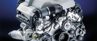
Diesel engine fuel system - Design and principle of operation
Vehicles equipped with diesel engines are the most sensitive to fuel quality. The fuel system of a diesel engine occupies one of the central places in the design of the power plant. Repairing and restoring the system is complex and expensive. Structurally, the fuel system of a diesel engine consists of two circuits - low and high pressure. From the first compartment, the prepared diesel fuel passes into the next circuit for direct injection into the combustion chamber.
Diesel engine power system: device
Diesel engine technology has come a long way in recent years. Almost half of all passenger cars sold in European countries are cars with a power unit modified for diesel fuel. Today, such engines no longer create clouds of thick black smoke, and the noise during operation of such an internal combustion engine is a thing of the past. Power units using solar fuel today are not only economical, but also more environmentally friendly compared to units using gasoline. Such cars have higher power characteristics, and dynamic performance has become tens of times better. A modern diesel engine is quieter. Let's look at how it happened that such internal combustion engines better comply with emission standards and significantly benefit in traction and economic parameters.
Description of the diesel fuel system design
The diesel engine fuel system consists of the following components:
- Fuel tank.
- Main fuel lines.
- Low pressure pump.
- Coarse and fine fuel filter.
- High pressure fuel injection pump.
- Dispensers with spray nozzle.
As mentioned above, the system is divided into separate circuits that operate under different pressure conditions. The low pressure circuit consists of:
- fuel filter;
- separator;
- special drive mechanism;
- Heater;
- fuel injection pump.
As fuel passes through each element, it is transformed:
- When heated, cold, condensed diesel fuel becomes soft.
- The filter element cleans the fuel from foreign particles and other impurities.
- The pump provides the necessary fuel pressure to supply the second higher pressure compartment.
The design of the second circuit includes the following devices:
- fuel injection pump (high pressure);
- fine filter;
- spray nozzles providing metered fuel injection;
- fuel pipeline system.
Liquefied fuel under pressure is supplied to the cylinders through fuel lines in the calculated quantity.
Main types of diesel fuel systems
The most widespread are 4 types of diesel engine fuel systems:
- in-line injection pump
- Distribution type injection pump
- pump injectors
- common rail system
In-line fuel injection pump is a solution that has been proven for decades and is actively used on trucks and special vehicles with diesel engines. This fuel supply system is based on the operation of a plunger pair. The cylinder moves in the sleeve, creating pressure and compressing the fuel to the required levels. Once they are reached, a special valve opens, supplying fuel to the injector, which injects it into the cylinder. At this time, the plunger moves down, opens a channel for injecting fuel into the space of the liner using a fuel priming pump, and the cycle repeats.
The operation of the plunger itself is made possible by the cam shaft, which is driven by the motor. The cams “push” the valves, and the injection timing gear, connecting the fuel injection pump and the engine, adjusts the operation of the fuel system.
The undeniable advantages of a fuel supply system with in-line injection pumps are their maintainability and availability of maintenance.
The distribution type injection pump is structurally similar to an in-line fuel pump. The difference lies in the number of plunger pairs. If in an in-line injection pump one pair goes to one cylinder, then in a distribution pump one plunger pair is enough to service two, three, and even six cylinders. This is achieved through the option of rotating the plunger around its axis. Rotating, the plunger alternately opens the exhaust valves, supplying fuel to the injectors of several cylinders.
The evolution of distribution injection pumps has led to the appearance of rotary fuel pumps: in them, plungers are placed in the rotor and, during operation, move towards each other while the rotor rotates them, thereby distributing fuel throughout the combustion chamber.
The advantage of a fuel supply system with a distribution injection pump is the compactness of the device itself. Disadvantages are the complexity of setup, the use of electronic control circuits and operation adjustments.
The system for supplying fuel to the cylinder using pump injectors generally eliminates the need for an injection pump as a separate element. In this case, the nozzle and the pump section are one unit in a common housing.
As a result, it is easy to adjust the fuel supply to a specific cylinder, and if one pump injector fails, the others continue to work, which makes repairs easier. Structurally, pump injectors drive the timing camshaft plungers in the cylinder head.
The pump-injector fuel supply system is common not only in trucks, but also in passenger cars. Its disadvantages include the high cost of spare parts, as well as extreme sensitivity to the quality of diesel fuel. The smallest impurities in the fuel can easily damage the pump injector, which affects the cost of operating such a solution in a personal car.
The Common Rail system has become a kind of breakthrough in terms of solving the fuel supply mechanism in diesel internal combustion engines. This system allows you to save fuel with high diesel efficiency, which is what made it so popular. Common Rail was invented by Bosch engineers back in the 90s. Today, most diesel vehicles are equipped with Common Rail.
The main difference of this system is the presence of a high-pressure accumulator in the common line. Fuel is pumped there by a separate injection pump and then supplied to the injectors under constant pressure. It is the constant pressure that makes it possible to quickly and efficiently inject fuel into the cylinder. The result is productive, smooth and comfortable operation of the diesel engine. A bonus is the simplification of the design of the injection pump itself in the Common Rail system.
The operation of the system is controlled by a separate ECU: a group of sensors tells the controller how much and how soon diesel fuel needs to be supplied to the cylinders. On the other hand, the complexity and disadvantage of Common Rail is due precisely to the smart electronics and operating principle of the system. Therefore, owners of such solutions should choose high-quality fuel and change fuel filters in a timely manner.
We wrote about how to further extend the life of your diesel engine here.
If you are looking for quality spare parts for your diesel engine, check out our catalog
GO TO CATALOG
Diesel Engine High Pressure Fuel Pump
In order for an internal combustion engine to produce the high power stated in its technical specifications, it is necessary to ensure the most complete combustion of fuel in the working cylinders. The main task of the fuel injection pump is to supply high-quality fuel to the combustion chambers. This device provides the following fuel supply conditions:
- at the right time;
- in the required quantity;
- at a given pressure (not less than 150 MPa).
The fuel supply time and its volume are calculated based on the crankshaft speed. These parameters remain stable and do not depend on operating conditions and engine load levels.
Design of a high pressure fuel pump for diesel engines:
- Mode controller.
- Exhaust connection.
- Valves.
- A pair of pistons with a drive mechanism.
- Pump element.
- Mechanism for adjusting the injection advance angle.
Thanks to the coordinated operation of the components included in the design of the internal combustion pump, the operation of the diesel internal combustion engine is ensured.
Features of diesel fuel and engines based on it
Like a gasoline engine, a diesel engine operates on the principle of burning liquid fuel in cylinders. But diesel fuel has some specific features, which lead to differences in the design of diesel and gasoline engines.
In terms of composition, diesel fuel is a mixture of gas oil and kerosene fractions obtained after gasoline is distilled from crude oil.
The main property of diesel fuel is its flammability index, which is called the cetane number (similar to the octane number for gasoline). Standard types of diesel fuels available at gas stations have this number ranging from 45 to 50.
Important: for modern diesel units, the higher the cetane number of diesel fuel, the better.
Diesel fuel is pre-cleaned at the factory, and the fuel filter removes foreign fractions “on site”. The purified fuel flows through the line to the injection pump (a high-pressure fuel pump included in a diesel engine, the purpose of which is to create outlet pressure), which supplies it to the nozzles, which spray fuel into the combustion chamber. There, diesel fuel particles mix with air heated by compression, and ignition occurs.
Important: this principle differs from gasoline engines, where the fuel is ignited by spark plugs: the power system of diesel engines is designed to operate from self-ignition of fuel under pressure. But diesel engines also have spark plugs: they use special glow elements to ensure the engine starts “cold” and maintain the desired temperature - they preheat the air entering the cylinders.
Diesel spark plugs:
Other important features of diesel fuel include its increased density and good lubricity. Other significant characteristics:
- fuel purity;
- viscosity;
- pour point.
According to the last parameter, it is customary to divide diesel fuel into:
- summer diesel fuel;
- winter;
- Arctic.
Diesel Engine Low Pressure Fuel Pump
The fuel injection pump is also part of the diesel fuel system. It is installed in close proximity to the HPF pump and is connected to it using fittings through which the fuel circulates. Diesel fuel is pushed out of the tank by a special pump. The fuel injection pump is often called a diesel fuel injection pump and consists of two service gears that are in constant motion. When they rotate, a flow of diesel fuel is created, directed towards the injection pump.
If you notice that the performance of the fuel injection mechanism of the fuel injection system has decreased, it is recommended to disassemble it for further cleaning and flushing. More serious repairs involve replacing damaged elements with new parts included in special repair kits.
Operating principle of a four-stroke cycle diesel engine
The first stroke, intake, serves to fill the engine cylinder only with air. As the piston moves from top dead center to bottom dead center, air is drawn in through the open intake valve.
The second stroke, compression, is necessary to prepare for the self-ignition of diesel fuel vapors. When moving to top dead center, the piston compresses the air 18-22 times (for carburetors 8-10 times). Therefore, at the end of the compression stroke, the vapor pressure of diesel fuel above the piston reaches 40 kg/cm2, and the temperature rises above 500°C.
The third stroke, the power stroke, serves to convert the energy of burned diesel fuel into mechanical work. At the end of the compression stroke, diesel fuel is supplied into the combustion chamber through a nozzle under pressure, which self-ignites due to the high temperature of the compressed air. When diesel fuel burns (diesel fuel vapor explodes), it expands and the vapor pressure increases. This creates a force that moves the piston to bottom dead center and turns the crankshaft through the connecting rod. During the working stroke, the pressure in the cylinder reaches 100 kg/cm2, and the temperature exceeds 2000°C.
The fourth stroke (exhaust gas release) serves to release the exhaust gases from the cylinder. The piston rises from bottom dead center to top dead center and, through the open exhaust valve, pushes out the exhaust gases. During its subsequent downward movement, the piston sucks in a fresh portion of air, the intake stroke occurs, the diesel fuel vapor explosion stroke occurs - and the working cycle repeats.
In a two-stroke cycle, power strokes occur twice as often and you can expect a significant increase in power compared to a four-stroke cycle. In practice, this cannot be realized.
Features of the diesel engine fuel system
Internal combustion engines running on diesel fuel differ from their gasoline counterparts in the principle of formation of the fuel-air mixture. In a gasoline engine, oxygen-enriched fuel fluid is forced into the combustion chamber and then ignited by a spark plug.
The process of forming the fuel mixture in a diesel power unit:
- The working cylinders of diesel engines are filled separately with air and fuel at different times.
- Air enters first and compression occurs.
- When it is compressed, the temperature of oxygen increases significantly (to more than 700 – 800°C).
- When the maximum temperature is reached, the fuel oil is injected into the combustion chamber under very high pressure (at least 5 bar).
- Instant spontaneous combustion occurs.
Interesting: the design of the diesel fuel system includes a so-called preheating system with special glow plugs made in the form of heating elements. Their task is to ensure rapid heating of the air space in the cooled engine compartment. When the ignition is turned on, the glow plugs heat the air in the fuel system of a diesel engine for a few seconds. When the unheated diesel engine has stabilized, the glow plugs are automatically switched off (after 15 seconds).
Types of fuel systems
Modern cars are equipped with diesel and gasoline engines that use different types of fuel supply. In addition, gasoline engines are divided into two more types: carburetor and injection engines.
Carburetor and its features
A carburetor is a special device responsible for mixing fuel with air. The carburetor is mounted on the intake manifold, to which fuel is supplied. In it, with the help of jets, fuel is mixed with air, then through the throttle valve it enters the manifold and is directed to the engine cylinders.
Operating principle of the injector
The fuel injection system is fundamentally distinguished from the carburetor system by the following nuances:
- in this system, fuel is supplied from the tank to a ramp connected to the injectors (sprayers);
- air to create the mixture enters through the throttle assembly;
- The pressure created in the fuel lines and pump far exceeds the pressure in the carburetor. This feature is associated with the need for rapid injection of the mixture into the combustion chamber;
- An electronic device is responsible for the operation of the fuel system (more precisely, for fuel injection).
Injection systems can be single-injection and distribution.
Single-injection injection systems are not the best option, since one injector cannot fully supply all cylinders with fuel.
On distribution systems, each cylinder has its own injector, so the engine runs at full power, and this is the reason why modern manufacturers prefer this system.
The fuel injection system begins its operation in the same way as the others: when ignited, the fuel pump turns on and fuel enters the fuel lines, but then it ends up in a ramp, in which it is always under increased pressure. From the ramp, fuel enters the nozzles, which are responsible for supplying fuel to the combustion chambers. The formation of a fuel-air mixture also occurs in them. The operation of the injectors is controlled by electrical equipment and various sensors, and it is based on their signal that fuel is injected.
A car cannot operate without an engine cooling system, about which you can read in more detail here. Read about the importance of the car brake system and its components here.
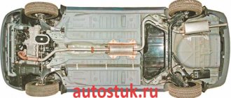
Diesel fuel system
The diesel fuel system diagram differs from those described above. In such a fuel system, fuel is supplied under high pressure, which causes it to ignite and start the engine to operate. In gasoline systems, the mixture is ignited by a spark plug. The pressure is ensured by the continuous operation of the injection pump (high pressure fuel pump).
Thus, in a diesel system there are two fuel pumps, one of which is responsible for pumping fuel from the tank, and the other is responsible for supplying fuel to the injectors.
The fuel system diagram of a diesel engine is more complex than the previous ones due to the abundance of structural elements. It all starts with the operation of the pump, which pumps fuel from the tank and directs it through the fuel lines through the filter to the injection pump. The fuel then enters the injectors located in the cylinder heads. In parallel with the supply of fuel, purified air enters the cylinders. The resulting mixture will already enter the combustion chamber.
The diesel system requires high precision and increased control, so maintenance of such engines is expensive.
Nowadays, different fuel systems are installed on cars, in which there are many common components that have the same characteristics. Of course, injection and diesel systems are more complex due to the increased accuracy of fuel injection, but the unification of parts can greatly facilitate repairs.
How does the diesel engine fuel system work?
The sequence of system workflows can be described by the following algorithm:
- The low pressure fuel pump pumps fuel into the system;
- after cleaning and filtration it enters the cavity of the fuel pump;
- The high pressure pump presses the fuel onto the spray nozzles;
- When the compressed air in the combustion chamber reaches its maximum temperature, part of the fuel under pressure is supplied to the cylinder in the form of atomized particles;
- ignition followed by fuel combustion.
How does the fuel system of a diesel car work?
How and which car compressor to choose
Just a couple of decades ago, most car enthusiasts only dreamed of owning such an accessory as a car compressor powered by a battery or cigarette lighter. But for today, having a tool that is undoubtedly useful for any car owner is commonplace. But great popularity has led to the emergence of a wide variety of compressors in design, quality and price. Therefore, we decided to touch upon such a topic as choosing a compressor for your car. Why buy a car compressor? The compressor was invented to make life easier for car owners in cases where it is not possible to go to a tire repair shop, or to facilitate the process of inflating various things - from an inflatable pillow to a large inflatable boat. (adsbygoogle = window.adsbygoogle || []).push({}); The choice of a hand or foot pump is supported by their relatively low cost and theoretically high productivity (if a person can pump air at a high rate and without interruptions). In terms of reliability, it all depends on the manufacturer and cost. Therefore, in this matter it is not correct to compare pumps and compressors. But a car compressor is primarily attractive due to its ease of use without the need to use your own strength to inflate the wheels. And this factor plays a fundamental role in favor of compressors. At the same time, the advantages are even more visible when there is a need to pump a large volume of air. What types of compressors are there? First of all, we can note two main types of compressors available for purchase. The first one is a portable tool for use in a car. The main advantage will be mobility and compact size. This allows you to safely transport the device in the luggage compartment of a car. Although such compressors have enough power to inflate car tires, they are absolutely not suitable for domestic use. But if you need to use a compressor and compressed air at home. For example, for painting with a pneumatic spray gun, or there is a need to use another pneumatic tool, it is better to choose a large compressor with a receiver for storing compressed air, operating from a 220V network. But this article is aimed at those who want to purchase portable compressors for their car. Therefore, we will look at large household appliances in another article. Types of compressors by design Today, piston and membrane compressors are the most common. Both designs have their pros and cons. Therefore, let’s take a closer look at both designs in order to better understand the capabilities of the tool when purchasing in a store. Piston Piston compressors have a design similar to that of internal combustion engines. The only difference is that the piston in the compressor serves only to pump air, and is driven by an electric motor. The main advantage of this design is performance and power. Despite its modest size, a piston compressor is capable of inflating a wheel to 8 atmospheres in a short time. But the design itself and high pressure dictate rules that require the use of high-quality steel for the manufacture of all compressor parts. Therefore, most of the options provided for choice will not work as long as we would like. Most of the models sold in markets or stores are imported from China, and their cost is much lower than the adequate cost of a high-quality piston compressor. But if there is a need to use a compressor of this particular design, then you should pay attention to the brand stores of famous companies, and come to terms with the higher cost than that of membrane designs. Electric diaphragm pumps Diaphragm compressors are distinguished by their simple and inexpensive design. But they also have a rather big disadvantage - this is the ability to inflate wheels to a maximum pressure of 3 atmospheres, and the inflation speed is lower than that of piston ones. But the simplicity of the design provides greater reliability and lower cost. The principle itself is based on the fact that a special membrane is made of wear-resistant and elastic material, which performs reciprocating movements under the influence of an electric motor. In most cases, a tool of this design will be enough for most cars and their owners. Which compressor to choose? As it became clear from the article, there are only two designs on the market, but the main problem when choosing is the choice of a specific model with certain characteristics and a certain manufacturer, which greatly affects the final cost. Things to remember when choosing a compressor: • You should determine the required compressor power for your conditions. Undoubtedly, everyone always wants something more powerful and cooler, but the real need can cost much less; • Dimensions are also an important argument for choice. But there are two nuances here - the smaller the compressor, the more convenient it is to transport it, but smaller dimensions mean a decrease in power. Therefore, compromises will have to be sought for the final solution; • Compressor design plays a role in the final purchase price and capacity. Therefore, this point is resolved automatically when determining the previous points. • The manufacturer influences the quality and cost, but here you will have to choose based on your capabilities, preferences and reviews of other consumers. It can be repeated once again that most motorists do not need to purchase powerful compressors. Moreover, some inexpensive manufacturers may overestimate the performance of their models. Therefore, you should be careful about “powerful” but cheap models. Such options may not correspond to the declared power and performance, or will fail after several uses. In addition, it is worth remembering that the maximum pressure for compact compressors is limited to eight atmospheres. Therefore, you should not trust manufacturers who indicate a higher value on their products. Also, an important parameter may be productivity, measured in liters of air pumped per minute. This indicator plays a major role in the speed of wheel inflation. Moreover, the larger the wheel itself, the preferable it is to purchase a more efficient compressor. The rest of the advice may be of a general informational nature and not directly related to automobile compressors. First, before purchasing, you should clarify the availability of a warranty and the conditions for its provision. Secondly, you need to carefully inspect your future purchase for defects, defects, chips or signs of use. And to get acquainted with the approximate prices, you can visit an online store that sells compressors for car tires - https://akbenergo.ru/catalog/compressors/.View the news
The most common malfunctions of the diesel engine fuel system
The most common diesel fuel system problems include the following:
- Difficulty starting the engine.
- Reduced power.
- Increased fuel consumption.
- The appearance of different shades of smoke coming out of the exhaust pipe.
- Increased operational rigidity.
- Inability to accelerate (it is recommended to increase the accelerator pedal stroke if there is a delay in acceleration).
- Instability of idle speed (fluctuates).
- The engine stops frequently.
Difficult start
To make it easier to start diesel engines in winter, manufacturers produce a special fuel called “Arctic”. However, the cause of a difficult start is not always frozen diesel fuel. If the diesel engine cannot be started when cold, check.
- quality of high pressure pump discharge parts;
- degree of wear of injectors;
- adjusting the fuel advance angle;
- spark plug;
- Pressure regulator;
- Loss of fuel lines.
Power reduction
The performance of a diesel engine is reduced due to malfunction, clogged fuel filters and spraying of the injector holes. When the filter elements fail, the amount of diesel fuel sent to the fuel pump is sharply reduced, which negatively affects engine performance.
Increased diesel fuel consumption
An incorrectly set injection advance angle is the main reason for high fuel consumption. Incorrect operation of the injection pump also affects fuel consumption. It is necessary to regulate the level of mixture pressure during injection. Reduced compression in the working cylinders can also be the cause of high diesel fuel consumption.
Exhaust black
If dark smoke comes out of the exhaust system, it is recommended to check the quality of the mixture. Violations can be caused by delayed fuel injection, which does not have time to completely burn and settles on the cylinder walls in the form of carbon deposits. Carbon deposits often form on the valves and do not close properly.
The appearance of white smoke in the form of steam does not cause alarm, as it quickly disappears after the engine warms up. This is especially common in diesel engines operating in northern latitudes.
Fuel system malfunctions
The main reason for any malfunction of the diesel engine power system is wear of structural elements and components. Typical malfunctions that occur after a certain mileage of the engine are wear of the governor lever axis and failure of the rubber seal ring in the low-pressure line.
Another common problem is the accumulation of dirt and carbon deposits in components and lines, which should be regularly removed from the engine by flushing.
Other typical faults:
Difficulty starting the engine.
Possible reasons:
- faulty glow plugs;
- wrong type of diesel fuel;
- airing of the system;
- wear of fuel injection elements;
- malfunction of the booster pump/injection pump;
- incorrectly set fuel supply advance angle;
- failure of system regulators or sensors.
The engine has lost power.
Probable reasons:
- wear of fuel injection pump parts or misalignment;
- incorrectly set advance angle;
- worn out or failed injector nozzles;
- system pressure is too low;
- airing;
- breakdown of the booster pump;
- clogged filters.
Too much diesel consumption
Causes:
- incorrect lead angle;
- wear or misalignment of the injection pump;
- damage to nozzles or their wear;
- injection pressure drop;
- air filter clogged;
- poor compression;
- fuel leaks from the system;
- poor tightness of the fuel supply system;
- clogging of the fuel drain line (coming from the injection pump to the tank);
- failure of the diesel fuel intake advance or incorrectly set idle speed;
- other internal combustion engine malfunctions.
Fat black exhaust from the pipe
Causes:
- incomplete closure of valves or formation of carbon deposits, leading to poor combustion of the mixture;
- injection too late;
- incorrectly set valve clearances;
- compression drop in cylinders;
- poor fuel spray generated by the injectors.
The exhaust is white or gray and very smoky.
Causes:
- compression drop;
- cylinder head gasket breakdown;
- incorrect fuel supply advance;
- The engine is overcooled and needs to be warmed up.
The engine feels like it's running too hard
Causes:
- injection occurs too early;
- the mixture enters the cylinders unevenly;
- misaligned or faulty injectors;
- reduced compression.
The engine is noisy
Causes:
- one or more components of the fuel system are dirty (filters, injectors);
- the system is airy;
- problems with the sealing washers of the nozzles or the nozzles themselves.
Uneven operation at idle and when driving
Causes:
- idle speed is set incorrectly;
- problems with the fuel line in the area between the filter and the injection pump;
- damage to the fuel injection pump support plate;
- advance is set incorrectly;
- problem with nozzles or nozzles, general problems in the fuel system;
- malfunction of the crankshaft speed controller;
- excess pressure of crankcase gases.
Cleaning the diesel engine fuel system
The use of low-quality diesel fuel with a high sulfur content leads to the formation of harmful deposits on the active parts of the fuel system and reduced performance. In particular, the injector holes become clogged with deposits that harden when exposed to high temperatures. Under the influence of these factors, the following occurs: the throughput of the sprayers decreases, the direction of the jet changes, etc. A car owner is faced with a natural problem - how to bleed the fuel system of a diesel engine.
It is best to entrust system cleaning measures to professionals. If special equipment is available, the injectors are disassembled and checked on diagnostic stands. However, this method is labor-intensive with serious material costs.
Experienced drivers wash the fuel system of a diesel engine with their own hands in a garage. To do this, they use a simplified method: adding a special liquid to the fuel tank. It is recommended to perform this procedure every 3-5,000 km.
The most popular among car owners are diesel injection cleaners:
When choosing the best fuel system cleaner for your car, you need to research the features of each product and read consumer reviews. Thanks to timely maintenance of the diesel engine, the service life is significantly increased and the technical characteristics of your car are improved.
The main function of the fuel system, description of its operation
The purpose of the diesel engine fuel system is to supply a precisely measured volume of diesel fuel into the cylinders, at a specific point in time and under a certain pressure. Therefore, due to the need to ensure a constantly high pressure, as well as due to high requirements for accuracy of operation, the fuel system of a diesel engine will be more complex in design than that of a gasoline engine, and is quite expensive.
Now let’s try to imagine the uninterrupted operation of the fuel system in a step-by-step mode, and for this we will analyze its individual components in order. So, the fuel tank serves to accommodate diesel fuel and ensure its uninterrupted supply to the system. This function is performed by pipelines. First, the fuel priming pump sucks fuel from the tank and supplies it through filters to the low-pressure distribution line. At the same time, a stable pressure of three atmospheres is maintained in the system. The fuel is filtered twice, passing through coarse and fine filters.
The task of fuel filters is to control the purity of the fuel and rid it of possible foreign impurities - particles of dirt, water, grains of sand. Gone are the days when diesel engines were very unpretentious in terms of fuel quality. Modern diesel engines require very clean diesel fuel to maintain decent performance. Clean fuel is now one of the main and indispensable conditions for efficient engine operation. Fuel is supplied only if there is no air in the system.
After filtration, the diesel fuel enters the high pressure line. This part of the fuel system ensures that the required amount of fuel is supplied and injected into the engine cylinders at certain moments. The high-pressure fuel pump, in accordance with the operating order of the cylinders, supplies diesel fuel to the injectors through high-pressure fuel lines.
Injectors located in the cylinder heads inject and spray fuel into the combustion chambers of the engine. Since the fuel priming pump constantly supplies the high-pressure fuel pump with fuel “with a reserve”, that is, slightly more than needed, its excess, and with it the air that has entered the system, is discharged back into the tank through special drainage pipelines.
To ensure synchronous fuel injection, a special fuel frame is installed, to which the injectors are connected. They are located in the intake pipe with their heads and spray fuel immediately at the moment of its supply.
Yes, by pressing the pedal, the driver or machine operator no longer increases the direct fuel supply, as was the case in carburetor engines of past years. But it only changes the operating programs of the regulators, which themselves vary the volume of simultaneous fuel supply, according to strictly defined dependencies on the speed, boost pressure, position of the regulator lever, etc.
Diesel fuel
Diesel fuel is one of the petroleum products. Contains various hydrocarbons (paraffins, naphthenes, aromatics, etc.). The number of carbon atoms in diesel molecules reaches thirty. The main quality of diesel fuel is its ease of ignition when in contact with hot air. The flammability of a fuel is characterized by the amount of cetane. The higher this number, the less resistance to oxidation of fuel molecules and the easier it is to ignite. Diesel fuel has a cetane number of 40-50 (usually 45).
An important characteristic of fuel is also its viscosity at different temperatures. For proper engine operation, the fuel must not freeze at low temperatures (up to -60 °C). In addition, the fuel must be non-toxic, have anti-corrosion and lubricating properties, and must not create vapor locks in fuel lines at temperatures up to 50 °C.
For automobile diesel engines, fuel classes A (arctic), 3 (winter) and L (summer) are used. The most common fuel grades are Z (at subzero air temperatures) and L (at temperatures above 0 °C).
Requirements for units and components of the power supply system
The following basic requirements apply to all units and components of the power system:
- estate
- Reduced weight and dimensions
- reliability
- corrosion resistance
- low hydraulic resistance
- simplicity
- low operating costs
Fuel lines and fuel system assemblies must be located in the vehicle's engine compartment in such a way that, in the event of a malfunction, dripping fuel will not reach parts at a temperature that could cause it to ignite.
Functions of the diesel engine power system
The purpose of the diesel engine power system is to supply fuel to the injectors and then into the cylinders under high pressure. A set of devices is responsible for this, ensuring continuity, accuracy and consistency of the process. Features of diesel power systems:
- diesel fuel is supplied for injection in precisely measured doses, depending on the current load and operating mode;
- the injection intensity is also adjusted depending on the load at a particular time;
- ensures efficient atomization and distribution of diesel fuel throughout the combustion chamber;
- Before entering the pump, fuel line and engine, the fuel is filtered to avoid contaminating the injectors and other critical components.
General structure of the power system
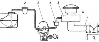
The figure shows a diagram of the fuel supply system of a heavy diesel engine. As a rule, the fuel supply system includes units located outside the engine (on the chassis or in the body of the car) and on the engine. The first include a fuel tank 7 for collecting fuel, a fuel supply pump before starting 10, a fuel distribution valve 77, low pressure fuel lines and some other components. The latter mainly include the main fuel booster pump 8, the high-pressure fuel pump (HFP) 5, the injectors 4 and the high-pressure fuel lines.
When the engine is running, fuel from the tanks is taken from the main fuel pump and, under a pressure of 0.05...0.1 MPa, is supplied to the fuel injection pump. On the way from the tanks to the pump, the fuel passes through the fuel distribution valve, pre-pump and coarse filter 9. If the car has only one fuel tank or several tanks communicate with each other, there is no fuel distribution valve. Before fuel is supplied from the pump to the injection pump, it is cleaned of the smallest impurities in fine filter 3. The injection sections of the fuel pump, driven by the crankshaft, supply fuel under high pressure (up to 50 MPa or more) in the required quantity to the nozzles. Through injectors screwed into the cylinder head, fuel is injected into the combustion chambers at the end of the compression stroke in the cylinders.
Rice. diagram of the fuel supply system of a heavy diesel engine: 1 – fuel tanks; 2 – air valve; 3 – fine filter; 4 – nozzles; 5 – fuel injection pump; 6 – engine; 7 – fuel collection tank; 8 – main fuel filling pump; 9 – coarse filter; 10 – pump for filling starting fuel; 11 – fuel distribution valve; fuel lines are indicated by a solid line; lines for removing air from the system are indicated by a dotted line
Before starting the engine, the system is charged with fuel and supplied to the fuel injection pump from the fuel pump before starting. After starting the engine, this pump does not work.
If air enters the high pressure and high pressure lines connecting it to the injectors, the fuel supply to the cylinders is disrupted. As a result, the normal operation of the engine is also disrupted. To prevent air from entering the fuel injector, an air separator is installed on the path from the fuel to the injector, located at the highest point of the system. Typically the air separator is located in the fine filter cover. Before starting the engine, if necessary, the air accumulated in the air separator is discharged into the air cavities of the fuel tanks 1 through the air release valve (valve) 2. To do this, when the engine is turned off, open the tap (valve) and use the pump to pre-start the system. In this case, the fuel moves air from the pan into the cavity of the fuel tank through the fuel distribution valve (as shown in the picture) or directly.
Diesel power system design
What does the diesel fuel system consist of:
- Fuel tank.
- Coarse fuel filter (GOT).
- Fine fuel filter (FTF).
- Pump for pumping up diesel fuel.
- High pressure fuel pump (HFP).
- Injection nozzles.
- High pressure line.
- Low pressure pipeline.
- Air purification filter.
These elements are found in all modifications of diesel units. Some engines are equipped with additional elements: an electric pump, particulate filters, mufflers, etc.
The diesel engine power system consists of two main parts:
- diesel fuel supply device;
- diesel air supply device.
The fuel supply device can be in a single housing, or it can be separate. The modern device is of a separate type, that is, the injection pump pump and injectors are located in different housings. Diesel fuel is pumped through low and then high pressure lines. Everything up to the injection pump is low pressure pipelines. After the injection pump, fuel compression begins.
The diesel engine power supply system is equipped with two pumps:
- High pressure pump;
- fuel pump.
The boost pump begins to pump fuel from the tank, drives it through the coarse and fine filters and delivers it to the high pressure fuel pump.
The injection pump pump supplies fuel under pressure to the injection nozzles in the manner characteristic of a given diesel engine. The fuel injection pump device has many identical sections.
Integral fuel supply system
The diesel engine power supply system is of a non-separated type, that is, the fuel injection pump and injectors are located in one housing, and is installed in two-stroke diesel engines. A device that contains both an injection pump and an injector is called a pump injector.
Such engines with continuous fuel supply have not spread en masse. They often break. Although the design is simpler, there is no high pressure line. Motors operate with high noise levels.
Separate fuel supply system
In such engines, injectors are installed in the cylinder head. Injectors must efficiently spray fuel throughout the working combustion chambers of the cylinders, so a common problem with poor diesel performance is clogging of the injectors.
The fuel pump pumps a lot of fluid into the injection pump, the high-pressure pump takes the volume it needs, and the rest flows through the drain lines back into the fuel tank.
Classification of diesel injectors by design:
- a closed nozzle, that is, its nozzle is closed with a special shut-off needle;
- open nozzle.
Four-stroke engines have closed-type injectors. The internal space of the nozzle communicates with the combustion chamber only during fuel supply.
The main element of the injectors is the atomizer. The sprayer may have only one hole or several. Fuel injection through these holes creates a flame in the cylinder. The shape and location of the torch depends on the throughput and number of holes.
Fuel tank
Spilled fuel in the nozzles between the needle and the sprayer is discharged through drain pipes into a special tank 7 or any main fuel tank.
Fuel tanks are used to store fuel. They can have different configurations and capacities depending on the design of a particular vehicle. The total capacity of the fuel tanks is determined by the vehicle's flight range (usually at least 500 km). Most often, tanks are made of sheet steel or high-strength plastic that is resistant to chemically active fuel. To prevent corrosion, the internal surfaces of steel tanks are coated with bakelite paint, galvanized or tinned. To increase the rigidity of tanks, cast slides are sometimes installed on their walls, and solid partitions are installed inside, which also reduce the free surface of the fuel and weaken its vibrations bkv while the car is moving.
Fuel tank necks are usually equipped with filters. The bottom of the tanks is equipped with settling tanks. If the tank has a significant capacity, the fuel is drained through an opening with a cap and a ball valve located above the crankcase. In this case, a special pipe with a hose is used. The air space of the tanks is connected to the atmosphere through drainage pipes or other special devices, which should exclude the possibility of fire entering the tank and fuel loss due to sudden vehicle impacts, and also (if possible) ensure purification of the air entering the tanks. In the past, dipsticks were used to measure the amount of fuel in tanks. Today, electric float sensors are most often used for this purpose, which send an electrical signal proportional to the fuel level to a corresponding indicator on the vehicle's dashboard.
Fuel lift pump
The main fuel priming pump ensures an uninterrupted supply of fuel from the fuel tanks to the fuel injection pump while the engine is running. It is usually driven by a crankshaft or camshaft. You can also use a self-contained electric motor powered by a motor generator. The electric drive ensures uniform fuel supply regardless of the crankshaft speed and the possibility of emergency shutdown of the entire system. There are several designs of fuel feed pumps. May be:
- gear
- plunger
- rotary (plate type)
Typically, plunger and rotary vane pumps are used.
Plunger fuel priming pump
The piston fuel filling pump consists of a housing 5, a plunger 7 with a spring 6, a pusher 10 with a roller 77, a spring 9 and a rod 8, and valves - inlet 4 and outlet 1 with springs. The pusher with plunger can be moved up and down. The upward movement is carried out by rotation of the eccentric shaft 72, which is made in the same housing with the camshaft of the fuel pump; downward movement is ensured by springs 6 and 9.
When the eccentric pin is deflected by the eccentric roller, the piston moves downward under the action of spring b, displacing the underlying fuel into the pump discharge line. At this time, the discharge valve is closed while the inlet valve is open due to the vacuum above the piston, and fuel flows from the inlet line into the cavity above the piston. As the valve and piston move upward, the inlet valve closes under fuel pressure and the outlet valve opens, allowing fuel to flow from the upper chamber to the lower chamber below the piston. Thus, fuel injection occurs only when the piston moves downwards.
If the fuel supply to the engine cylinders is reduced, the pressure in the pump exhaust pipe increases, and, consequently, in the cavity under the piston. In this case, the piston cannot lower even under the action of spring 6, and the piston and rod move at idle. As fuel is consumed, the pressure in the unloading cavity decreases, and the piston, under the action of spring 6, again begins to move downward, providing fuel supply.
Diagram of a plunger fuel pump: 1 – exhaust valve; 2 – fuel pump housing; 3 – fuel pump piston; 4 – suction valve; 5 – fuel filling pump housing; 6, 9 – springs; 7 – piston; 8 – rod; 10 – pusher; 11 – roller; 12 – camshaft eccentric.
Rice. Diagram of a rotary vane fuel pump: 1 – reduction spring; 2 – pressure reducing valve; 3 – overflow valve; 4 – overflow valve spring; 5 – float pin; 6 – plate; 7 – rotor; 8 – guide cup; AB – pumping chambers
The plunger fuel priming pump is usually combined with a manual fuel priming pump 2. This pump is installed at the inlet of the main fuel pump and is manually controlled by moving the piston 3 with the piston rod. As the piston moves upward, a vacuum is created beneath it, the suction valve opens, and fuel fills the space under the piston. As the piston moves down, the intake valve closes and the exhaust valve opens, allowing fuel to flow further down the fuel line.
Rotary fuel priming pump
In high power and high speed diesel engines, mainly rotary fuel pumps . The pump rotor 7 is driven by the motor shaft. The rotor has grooves into which plates 6 are inserted. One end (outer) of the plates slides along the inner surface of the guide of the cup 8, and the other end (inner) slides along the circumference of the floating pin 5, located eccentrically with respect to the rotor axis. At the same time, they alternately move out of the rotor and then slide into it. The rotor and plates divide the internal cavity of the guide bowl into chambers A, B and C, the volumes of which continuously change as the rotor rotates. The volume of chamber A increases, so a vacuum is created in it, under the influence of which fuel is sucked from the inlet line. The volume of chamber B decreases, the pressure increases, and the fuel moves into the discharge cavity of the pump. The fuel in chamber B flows from the cup inlet to the outlet. When the pressure in the discharge cavity rises to a certain level, the pressure reducing valve 2 opens, overcoming the force of the spring 7, and excess fuel is returned back to the inlet cavity of the pump. Therefore, constant pressure is maintained in the exhaust cavity and in the exhaust line. Before starting, when the engine and therefore the main fuel pump is not running, fuel can be supplied through it using a pre-pump. In this case, the bypass valve 3 opens, overcoming the force of the spring 4. In the closed position, the pallets of this valve block the pallet holes of the pressure reducing valve.
Lecture 18. General design and operation of the diesel engine power system.
Lecture 18. General design and operation of the system
diesel engine power supply.
Diesels are engines with internal mixture formation. Air and fuel are supplied separately to the diesel cylinders and, mixing with exhaust gases, form a working mixture. In this case, the mixture formation process takes place in a very short time (about 0.001 s).
Fuel for diesel engines. Diesel fuel has the following main grades:
L - summer fuel, intended for engine operation at ambient temperatures above 0 °C;
3 - winter fuel, intended for engine operation at ambient temperatures from 0 to -30 “C;
A - arctic, designed for engine operation at ambient temperatures below -30 °C.
The freezing temperature of diesel fuel should be 10... 15 °C below the ambient temperature of the operating area. The lower the freezing temperature of the fuel, the more reliable the operation of the diesel engine.
The ignition temperature of diesel fuel is 300... 350 °C.
The quality of diesel fuel is assessed by the cetane number, which is conventionally taken to be 100 units.
Cetane is a highly flammable fuel.
For diesel fuels, the cetane number should be within 40 ... 45 units. The higher the cetane number of diesel fuel, the more economical and smoother the engine runs. To increase the cetane number, a special additive is added to diesel fuel - isopropylene nitrate.
The diesel power system consists of the following three systems: fuel supply, air supply and exhaust gas exhaust.
Design and operation of the diesel fuel supply system. The fuel supply system serves to purify the fuel and distribute it evenly in dosed portions into the engine cylinders. This system includes a fuel tank, coarse and fine filters, a fuel priming pump, a high-pressure fuel pump, injectors and fuel lines.
Fuel pump 7 (Fig. 2.51) sucks fuel from tank 2 through coarse 4 and fine filters and directs it to high pressure pump 5. In accordance with the operating order of the engine cylinders, the high pressure pump will supply fuel to the injectors 11, which atomize and inject fuel into the engine cylinders 12.
Fuel booster pump 7 will supply more fuel to the high-pressure pump than is necessary for engine operation. Excess fuel is discharged through fuel line 3 back to the fuel tank. Fuel line 10 carries fuel leaked from the injectors into the tank.
Rice. 2.51. Diesel fuel supply system diagram:
1 — fuel receiver; 2 — tank; 3, 9, 10 — fuel lines; 4.8 - filters; 5, 7—pumps; 6— handle; 11 — nozzle; 12 - cylinder
The high-pressure fuel pump serves to supply the required portions of fuel through the injectors into the engine cylinders under high pressure (20...50 MPa) at certain times. The pump consists of sections of identical design, the number of which is equal to the number of engine cylinders. Each pump section is connected by a fuel line 13 (Fig. 2.52) to an injector 16. The plunger 6 and liner 5 of the pump sections are made with high precision and surface cleanliness. The gap between them does not exceed two microns. The plunger has a vertical groove 9, a beveled edge 11, and an annular groove 7. Gear 2, mounted on the plunger, is meshed with a rack 3, the movement of which rotates the plunger in the sleeve. Spring 4 presses the plunger against eccentric 1 of the pump camshaft, which is driven into rotation by the crank. The sleeve has an inlet 8 and an outlet 10, and a discharge valve 12 is installed in its upper part. Spring 1 presses the injector needle 15 to the nozzle 18 and closes the cavity 17, which is filled with fuel. When the plunger 6 is in the lower position, holes 8 and 10 are open and fuel circulates through them above the plunger. In this case, the discharge valve 12 is closed and excess fuel pressure is maintained in the injector cavity 77. When the plunger moves upward and the cam rotates, the outlet port 10 is closed, and then the inlet port 8: Under fuel pressure, valve 12 opens and high pressure is created in the cavity 17 of the nozzle. In this case, the injector needle 15 overcomes the resistance of the spring 14, rises up and fuel is injected into the engine cylinder through the opened nozzle 18.
Fuel injection ends when the edge 11 opens the outlet 10. In this case, the fuel pressure decreases, the needle 15 moves down and closes the nozzle 18. At the same time, the valve 12 closes and the fuel remains under excess pressure in the injector cavity 17.
By turning the plunger 6 in the sleeve 5, the end of the fuel supply and its quantity injected in one stroke of the plunger are changed. The fuel supply stops when the vertical groove 9 aligns with the outlet 10, and the engine stops. Connected to the high-pressure fuel pump are a fuel injection advance clutch, an all-mode engine speed controller and a fuel priming pump with a manual fuel pump.
Rice. 2.52. Fuel supply diagram and diesel cylinder:
1 - eccentric; 2 - gear; 3 - rack; 4, 14— springs; 5—sleeve; b— plunger; 7—groove; 8, 10 — holes; 9— groove; 11— edge; 12 - valve; 13 — fuel line; 15 - needle; 16— nozzle; 17—cavity; 18 - nozzle.
The fuel injection advance clutch is used to automatically change the fuel injection advance angle depending on the crankshaft speed. The clutch increases the efficiency of the diesel engine in various operating modes and improves its starting. The clutch is installed on the front end of the camshaft of the high pressure fuel pump and with its help the pump is driven.
The relative position of the driving and driven parts of the coupling is influenced by weights 2 (Fig. 2.53) located in housing 1. The weights are installed on axles 3 and are pressed by springs 4, which rest against spacers 5. When the engine is running and the crankshaft speed increases, the weights under by the action of centrifugal forces they overcome the resistance of the springs and diverge, while turning the cam block of the high-pressure pump as it rotates. As a result, the fuel injection advance angle a increases, and fuel enters the cylinders earlier. When the engine crankshaft rotation speed decreases, the weights converge under the action of springs and turn the pump camshaft in the direction opposite to its rotation, which reduces the fuel injection advance angle. The all-mode regulator is used to automatically maintain a constant crankshaft speed in accordance with the position of the fuel pedal at different engine loads.
The regulator also sets the minimum idle speed and limits the maximum idle speed. The regulator is driven by the camshaft of the high pressure fuel pump. The fuel supply pedal 6 (Fig. 2.54) is connected to the lever 2 for controlling the rack 1 of the pump; an extended spring 3 acts on the lever with a force Rir. When the engine is running, force Qvp is transmitted to lever 2 through thrust bearing 7 from rotating weights hinged on shaft 9, which is connected to the cam shaft of the high-pressure pump.
Rice. 2.53. Fuel injection advance clutch:
1 - body; 2 - load; 3 - axis; 4 - spring; 5 — spacer
Rice. 2.54. All-mode crankshaft speed regulator:
1 - rail; 2 — lever; 3 - spring; 4, 5 — stops; 6— pedal; 7 — thrust bearing; 8 — cargo; 9 - high pressure shaft through
If the engine operates at a crankshaft rotation speed corresponding to a given position of the pedal 6, then the force of the weights 8 is balanced by the force of the spring 3. As the crankshaft rotation speed increases, the regulator weights diverge. They will overcome the resistance of the spring and move rack 1. In this case, the fuel supply will decrease and the rotation speed will not increase. When the crankshaft rotation speed decreases, the weights will converge, the spring rack 1 will move in the opposite direction by force P11P and the fuel supply will increase, and the crankshaft rotation speed will increase to the value specified by pedal position 6. Minimum idle speed and maximum crankshaft rotation speed engine are limited by respectively adjustable stops 5 and 4.
Rice. 2.55. Scheme of operation of fuel priming pumps:
A, B - cavities; 1,2— pistons; 3, 5, 6, 10 — springs; 4, 9 — valves; 7 — rod; 8 - eccentric
The fuel priming pump is used to create the required fuel pressure and supply it in the required quantity to the high pressure pump.
The pump is a piston type and is driven by the cam shaft of the high pressure pump. In the pump body there is a piston 1 (Fig. 2.55), which is pressed against the rod 7 by a spring 5. The rod rests through the roller on the eccentric 8 of the cam shaft. The pump housing has inlet 4 and discharge 9 valves.
When, under the action of spring 5, the piston moves to the eccentric, fuel from cavity B is forced out into the fine filter and high-pressure pump. At the same time, the increasing cavity L is filled with fuel, which comes from the fuel tank through the coarse filter and inlet valve 4. When the piston moves in the opposite direction under the action of the eccentric 8, fuel from cavity A through the discharge valve 9 enters cavity B.
When the engine is not running, fuel is pumped into the high-pressure pump with piston 2 of the hand pump using the handle.
Injectors are used to inject fuel under a certain pressure and atomize fuel into the engine cylinders.
The injectors are installed and secured in the cylinder head.
Housing 4 (Fig. 2.56) and nozzle 1 are connected by nut 2. Inside the nozzle there is a needle 9 that covers its nozzle holes. A pressure spring 8 acts on the needle through the rod 3, the tightening of which is adjusted with washers 7.
The fuel is supplied to the injector through the mesh filter 6 and enters the cavity of the needle 9. Under fuel pressure, the needle, overcoming the force of the spring 8, moves upward, opens the nozzle holes of the atomizer and through them fuel is injected into the engine cylinder. In this case, the fuel that has leaked between the needle and the nozzle is removed from the nozzle through channels in the entire body.
Design and operation of the diesel air supply system. The air supply system is used to take in ambient air, clean it from dust and distribute it among the engine cylinders.
Rice. 2.56. Nozzle:
1 - sprayer; 2 - nut; 3 - rod; 4 — body; 5— sealing ring; b—filter; 7 — washers; 8 - spring; 9 - needle
Rice. 2.57. Diesel air supply system diagram:
1 — air filter; 2 - filter element; 3 - grate; 4 - pipe; 5 - cap; 6 — ejector; 7 - engine
The air supply system includes an air filter and an inlet pipe. It can be turbocharged or non-turbocharged.
Air enters through the mesh of the cap 5 (Fig. 2.57) and the air intake pipe 4 into the air filter 1. In the filter, the air passes through the inertial grille 3 and sharply changes the direction of movement. First, the air is freed from large dust particles, which, under the influence of inertia and vacuum, are ejected through the ejector 6 installed in the exhaust pipe of the muffler into the surrounding air. Smaller dust particles are retained in the cardboard filter element 2. The purified air is supplied to the engine cylinders 7 through the intake pipeline.
The air filter (Fig. 2.58) consists of a housing 3, a cover 1 and a replaceable filter element 2, consisting of two perforated steel casings and corrugated cardboard between them. Connection 1 is designed to suck dust from the filter housing.
Rice. 2.58. Air filter:
1 - cover; 2—filter element; 3 - body; 4 — bracket; 5— 7 — pipes
Air enters the filter through pipe 5, is cleaned there and exits through pipe 6.
Supercharging is the supply of air to the engine cylinders during the intake stroke under the pressure created by the compressor. When supercharging increases the amount of air entering the engine cylinders, the amount of fuel burned and the engine power increases by 20...40%. Diesel engines usually use gas turbine supercharging (Fig. 2.59) with a turbocharger. When the engine is running, air is forced into the cylinders 1 under pressure by a centrifugal compressor 6, the impeller of which is driven into rotation by a turbine 5.
The turbine impeller, mounted on the same shaft as the compressor impeller, is driven by exhaust gases before they enter the muffler. To limit the air pressure during boost, the bypass valve 4 is designed. When the required pressure is reached (usually 0.2 MPa), the air presses on the membrane 2, the valve opens and bypasses part of the exhaust gases past the turbine 5.
On V-shaped diesel engines, from one to two turbochargers are installed for turbocharging. With two turbochargers, each of them serves its own bank of engine cylinders.
Rice. 2.59. Scheme of diesel turbocharging with air:
1 - cylinder; 2 - membrane; 3 - spring; 4 - valve; 5 - turbine; 6 - compressor
Diesel exhaust system. The exhaust system serves to remove gases from the engine cylinders and reduce exhaust noise. At the same time, the exhaust system ensures dust suction from the air filter.
Exhaust gases from the engine exhaust pipes enter the exhaust pipes 2 and 3 of the muffler (Fig. 2.60) and then through the flexible metal hose 6 into the muffler 7. From the muffler, the gases are released into the ambient air through the exhaust pipe 8 and the ejector 10. Through pipe 9, dust is sucked from the air filter into the ejector.
An auxiliary (engine) retarder is installed in the exhaust system.
Rice. 2.60. Diesel exhaust system:
1 - sealing ring; 2, 3, 8 — pipes; 4 — engine brake; 5 — pneumatic cylinder; 6 — sleeve; 7 — muffler; 9 - pipe; 10 — ejector
Pre-fuel priming pump
Before the engine starts, the system is primed with fuel and supplied to the injection pump 70. Early manually operated piston and diaphragm (diaphragm) pumps were popular. Today, however, centrifugal rotary vane pumps driven by a battery electric motor are increasingly being used. They provide faster fuel transfer, do not require the driver's muscular strength and can be used as an emergency pump in the event of failure of the main fuel pump.
Coarse and fine fuel filters
The fuel is cleaned of mechanical impurities and water in coarse 9 and fine 3 filters. The coarse filter, installed in front of the main fuel pump 8, traps particles of 20...50 microns in size, which make up 80...90% of the mass of all impurities. The fine filter, located between the main fuel pump and the fuel injection pump, retains impurities measuring 2...20 microns.
The following types of pre-filters are currently used in diesel engines:
- net
- tape-slot
- stripes
In strainer filters, the filter element is a wire mesh. It can be made in concentric cylinders through whose walls the fuel is forced, or in disc-shaped sections screwed onto a central pipe with holes in the wall connected to the exhaust pipe.
In a slotted tape filter element, the filter element is a corrugated cup with a profiled tape wrapped around it. Through the grooves between the turns of the tape formed by its protrusions, fuel from the space surrounding the filter element enters the cavity between the corrugated cup and the tape, and then into the cavity between the bottom and the lid of the cup, from where it is discharged through the outlet pipe.
The plate-slot filter element is a hollow cylinder made of identical thin round disks with bending protrusions. These protrusions create gaps between the discs. The fuel flows along the outer and inner surfaces of the cylinder, and is cleaned as it passes through the gaps between the disks. The cleaned fuel passes through the end holes of the discs at the top of the filter to the outlet.
Very often, a coarse filter is combined with a sedimentation tank for water in diesel fuel. In this case, it is necessary to periodically unscrew the sump lid to remove accumulated water.
In fine filters, cardboard elements of the “multi-beam star” type or cardboard packaging and felt disks are usually used as filter elements. Less common are frames with padding that absorbs tides (for example, mineral wool), frames with fabric or thread-like windings, etc.
Injection pump. Design and principle of operation
The high-pressure fuel pump 5 is designed for precise dosing of fuel and its supply to the injectors 4 at the required pressure and at a certain time. In in-line engines, this pump is located on the side of the engine, on the upper half of the crankcase. In V-engines it is installed in the cylinder separation. There are many types of GPU. In particular, relatively low-power diesel engines intended for automobiles typically have an HPF type distributor with a single piston distributor. However, powerful multi-cylinder diesel engines are often equipped with multi-piston pumps. An example of such an injection pump for a six-cylinder V-shaped diesel engine is shown in the figure.
The pump consists of a housing 5 with covers, six pump sections, a pump section drive and a piston rotation mechanism. Each pump section includes a piston 8, a return spring 11 with support washers, an outlet valve 3 with a seat, a spring and a retainer, as well as a nipple 2 and other auxiliary guides and fasteners. The drive mechanism of the pump sections consists of a camshaft 7 and roller tappets 6 with adjusting bolts. The piston rotation mechanism consists of pin bushings 10 with toothed rings and a gear rack 9 with bushings and a limiting screw. Along the sections, two longitudinal channels 1 and 4 are drilled into the pump body, which are connected to each other by transverse channels. Each piston is installed very precisely on the lining, which ensures high pressure with minimal fuel loss through the slots.
Rice. High pressure fuel pump: 1, 4 – longitudinal channels; 2 – suction; 3 – exhaust valve; 5 – pump housing; 6 – roller pusher; 7 – camshaft; 8 – piston; 9 – toothed rack; 10 – rotating bushing; 11 – return spring
The pump works as follows . The camshaft is driven from the engine crankshaft through a gear (the angular speed of the camshaft is 2 times less than the speed of the crankshaft). The rotating camshaft moves roller tappets 6 with their cams, which lift the pistons up.
The return stroke of the rods and pistons is ensured by return springs. Channel 4 is supplied with fuel from the fuel pump, pre-cleaned in a fine filter.
When the piston is in the down position, fuel from port 4 enters the cavity created above the piston. As the piston moves upward, the inlet port closes and high pressure fuel flows through the exhaust valve, fitting and high pressure fuel line to the nozzle.
Fuel injection occurs as long as the plunger cavity is connected to exhaust port 1 by axial, radial and helical grooves in the plunger. With a constant stroke of the plunger, determined by the height of the cam arm, the amount of fuel supplied to the injector is regulated by turning the plunger using a stand and a rotating bushing with a toothed ring. The threaded groove in the plunger is designed in such a way that it changes the distance from the edge of the branch hole associated with channel 7 to the edge of the cutting edge of the screw groove. At the same time, the length of the piston stroke during which fuel is injected also changes.
In order for the fuel supplied to the cylinders to burn out on time, and for the engine to develop maximum power, it is necessary to slightly increase the fuel injection advance angle as the crankshaft speed increases.
This angle is controlled by a special centrifugal clutch, which is installed in the pump housing and moves the pump camshaft to a certain angle in proportion to the speed of rotation of the crankshaft in the direction of rotation.
Scheme, device and principle of operation for a diesel engine
Common rail fuel system diagram
Diesel fuel supply systems have their own characteristics. There are three types of structures:
- Common rail (or battery);
- With pump injectors;
- Separated.
Common rail
The most popular fuel system for diesel engines is battery (or common rail) . It meets higher environmental standards. This is ensured due to the independence of diesel injection processes from engine operating modes.
Structurally, the common rail diesel power system has two main circuits:
- Low pressure section - consists of a fuel tank, low pressure pump, pipelines and filter.
- High pressure section - consists of a high pressure fuel pump (HPF), a pipeline, a ramp (accumulator) and injectors.
The operating principle of the diesel fuel system is the following sequence:
- The low pressure pump forces diesel from the fuel tank into the pipeline.
- Passing through the pipeline through coarse and fine filters, diesel is supplied to the high pressure pump.
- The fuel injection pump supplies fuel to the injectors, which are used to inject fuel into the cylinders.
- Air is supplied simultaneously with fuel injection.
Split and unit injector
Pump nozzle
The split fuel system consists of a fuel tank, pipelines, injection pump and injectors. In this case, the pump and nozzles are connected by long pipelines designed for high pressure. The divided circuit is actively used in the domestic automotive industry, since it is characterized by low cost and simplicity of design .
In turn, a pump injector is a device that simultaneously creates the required level of pressure and injects fuel. It is located in the cylinder head and is driven by a cam mechanism. The forward and return lines are implemented as channels located directly in the block head.
The operating pressure with this scheme is up to 2,200 bar.
This method has an important drawback - it is characterized by the dependence of pressure on the engine operating mode.
Nozzle
The nozzle is used to deliver fuel into the engine cylinder under high pressure in a fine spray.
A typical nozzle includes a body 5 with a sprayer 3, a guide pin 4 and a union nut 2, a spray needle 1 with a rod b, a spring 7 with a support washer, an adjusting screw 9 and a sleeve 8, a cap nut 10 and an inlet pipe 12 with a strainer 11 .The sprayer and the needle must be positioned very precisely on each other. In the upper part of the atomizer there is an annular channel and several (most often three) vertical fuel channels, and in the lower part there are central inlet and outlet channels with holes for spraying. The diameter of these holes is 0.2...0.4 mm. A needle with a lower conical end closes the exit channel. The nozzle is firmly connected to the nozzle body using a union nut. The fuel channel in the housing is connected to the annular channel of the sprayer through its vertical channels. The guide pin ensures that the sprayer is positioned correctly relative to the body.
Shaped nozzle: 1 – needle for spraying; 2 – union nut; 3 – sprayer; 4 – guide pin; 5 – nozzle body; 6 – rod; 7 – spring; 8 – bushing; 9 – adjusting screw; 10 – union nut; 11 – mesh filter; 12 – fitting for fuel inlet
Fuel supplied to the injector through the inlet pipe passes through the filter and enters its annular cavity through the fuel channels of the housing in the upper part of the nozzle. Having reached the required pressure in this cavity, which acts, among other things, on the conical strip of the needle, it rises, overcoming the resistance of the spring. At this moment, the outlet channel opens and through it the fuel enters the combustion chamber of the engine cylinder and through the spray holes.
After the fuel supply from the pump section of the VFC is interrupted and the pressure drops, the needle sits back in its seat, stopping fuel injection. Fuel spilled through leaks enters the upper part of the nozzle, and through the holes for screws 9 and nut 10 is discharged through a special tube into the fuel tank 7 to collect fuel.
Operating principle and diagram
The diesel engine power supply system has a different design. Although at first glance it may seem that an internal combustion engine running on diesel fuel does not have at least some differences from an engine running on regular gasoline. After all, there is nothing special here, but the structure and internal components of the unit are the same. And in fact, the power system of a diesel engine, the purpose of which is to supply the combustible mixture to the combustion chambers, has practically no differences. Here are the same pistons, cylinders, connecting rods. But this is only at first glance.
In fact, the main and fundamental difference is the diesel engine power system. Here you can see a significant difference in the methods of formation and ignition of a mixture of fuel and air. Both in a carburetor and in an ordinary injection unit, the mixture is created not in the cylinders, but in the intake tract of the system. Ignition of the mixture in such engines occurs not from a spark, but from temperatures in the cylinder.
The air supply system of a diesel engine supplies purified air to the cylinders, which is subsequently highly compressed and then heated to 900 degrees. High-pressure fuel enters the combustion chambers using the injection system at the moment the piston approaches its top dead center. The air is already quite hot, and when fuel mixes with air, ignition occurs. The mixture ignites, creating an increase in pressure. This entails noise and harshness in the operation of such motors. Thus, cheaper combustible substances can be used, and the engine can operate even on very lean mixtures. Hence the higher efficiency. This design of the diesel engine power supply system is characterized by higher efficiency and, accordingly, torque. Disadvantages include noise, vibration, reduced power per liter and some difficulties when attempting a cold start, as well as possible malfunctions (the power supply system of an older model diesel engine is more susceptible to low-quality fuel). However, in new modifications of cars designed for this type of fuel, these problems no longer exist.
Battery fuel supply system
Today, stringent emission requirements for internal combustion engines have forced diesel engine designers to look for new solutions in the field of fuel equipment. The fact is that even the most modern injection pumps are not able to provide sufficient fuel pressure to atomize it so finely that it could be completely burned in the combustion chamber.
Incomplete combustion leads to an increase in fuel consumption and, above all, to an increase in the concentration of harmful substances, in particular soot, in the exhaust gases. For this reason, diesel engines with direct injection are increasingly using a so-called battery fuel supply system.
The main difference between this system and the “classic” one is the presence of a common fuel rail (pressure accumulator), in which very high pressure is created during engine operation.
The fuel rail is connected by high-pressure lines to electronic injectors, the needles of which are moved by electromagnets according to signals from the engine control computer (electronic unit). This fuel rail system allows you to optimize engine performance in almost all respects.
Diesel engine
A diesel engine is a piston internal combustion engine that operates on the principle of fuel compression ignition. The main difference between a diesel engine and a gasoline engine is the method of supplying diesel fuel vapor (fuel-air mixture) into the cylinder and the method of ignition. In a diesel engine, air is introduced into the cylinder separately from the fuel and then compressed. Due to the high compression ratio (from 14:1 to 24:1), the air is heated to the auto-ignition temperature of diesel fuel (800-900°C). Diesel fuel vapors are injected into the combustion chambers by nozzles under high pressure (from 10 to 220 MPa) and ignite almost instantly.
A diesel engine can also have spark plugs, but they are glow plugs and heat the air in the combustion chamber to make starting easier. Thus, the most common definition of a diesel engine is: “A reciprocating internal combustion engine with compression ignition of the fuel vapor.” Due to its very high compression ratio, the diesel engine is characterized by higher efficiency (up to 50%) compared to a gasoline engine.