3.9 / 5 ( 52 voices)
The UAZ-452 was originally created for the Soviet armed forces as a medical service vehicle, where it was therefore dubbed the “tablet” (the civilian nickname is “loaf”).
Therefore, the design of the mechanisms, including the transfer case, is simplified as much as possible.
During operation, the entire transmission system is unpretentious, which is confirmed by half a century of practice. The only recommendation from the manufacturer is to periodically check the oil level and check the fasteners.
In addition, if necessary, the front linkages should be adjusted and the lever axles should be lubricated on a preventive basis. This mechanical unit, including bearings, does not require any further maintenance or adjustment.
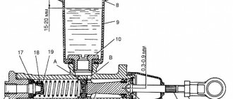
UAZ transfer case (“loaf”) - front axle drive shaft device
This gearbox is also equipped with this shaft. It is installed in the mechanism on two supports. The latter are ball bearings. To fix the shaft in the direction of the axis, a rear bearing is attached to it. It is installed in the same way as the one on the intermediate shaft.
The front support is not secured in the box body. The element is clamped to the shaft using the cardan shaft flange. The drive element of the front axle is a single piece together with the gear. The front part has slots. With their help, the shaft is connected to the flange on the cardan shaft.
What other elements does the distribution box consist of? The UAZ (“loaf”), the distribution device of which is described in the article, is equipped with gears with straight teeth. The drive has the ability to move along the splines on the secondary shaft of the gearbox. This gear has two rings. One is an involute type spline. They serve to connect direct transmission via the inner drive shaft ring of the rear drive axle. When the driver downshifts, this gear will engage the one on the intermediate shaft.
What else is special about this handout? The UAZ, the transfer case of which we are now considering, is equipped with a gear to engage the front axle of the car. It is positioned in such a way that it can move on splines located on the intermediate shaft. When the front axle is disengaged, the gear and shaft are separated. At the same time, it is in engagement with the drive shaft of the rear axle. This feature greatly facilitates gear shifting and promotes better lubrication. When the intermediate shaft rotates, the gear sprays oil onto all components.
UAZ transfer case
The crankcase, as well as its cover, are connected to the box using studs and nuts. Connection holes are located around the entire perimeter. Their accuracy and compatibility are ensured by two tubular-type pins. Treat the crankcase and its cover together. These parts cannot be exchanged for others from other crankcases. The front part has a precisely machined surface and a flange for mounting the transfer case on the gearbox.
There is a top hole on the crankcase. A thrust glass is installed into it by pressing. The latter rests on the outer part of a double-row angular contact bearing, which is mounted on the drive shaft. There is a hatch in the upper part of the crankcase. It closes with a lid.
The hatch is designed for mounting the power take-off mechanism. On the inclined surface of the crankcase at the top there is a hole for installing control levers, as well as rods for the transfer case control system. The hatch for filling and draining lubricant is closed using conical-type threaded plugs.
Rear axle drive shaft
How to use a transfer case in a field, box design
What does a UAZ transfer case consist of, what are its features? This shaft is mounted on two ball bearings. To protect the element from axial movements, it is held in place by a rear bearing with a thrust ring and a cover. A gear is attached to the front of the shaft. Its inner crown has slots. The function of this gear is to drive the front drive axle. Internal splines are required to engage direct transmission in the transfer case.
A screw-type gear is also installed on the splines between the bearings. It serves as a drive for the speedometer. The rear part of the shaft is connected to the cardan shaft using a nut with a conical protrusion through a flange. If you tighten this nut, its conical protrusion will bend into one of the grooves that are cut into the threads and stop.
Checking the transfer case
How to use a multimeter correctly
The advantage of the unit that distributes the torque impulse is that the device requires minimal intervention and maintenance. Manipulations consist of monitoring the level and changing the lubricant, inspecting connections for damage. Before working with the box, the product is cleaned. This helps detect hidden cracks and leaks. If such symptoms are detected, they find out what the cause of the phenomenon is. Faulty parts are replaced, as a rule, these are sealing elements and oil seals.
Read also: Button to open the trunk Solaris sedan
After cleaning and visually inspecting the surface of the transfer case, check the lubricant level in the product. If there is not enough liquid, the substance is added. At the same time, check the lubricant in the gearbox; the value corresponds to the lower edge of the filling hole. If the fluid level in the transfer case is low, but is high in the gearbox, topping up is not necessary, since the total amount of the substance has not changed.
A detailed inspection of the box involves dismantling the product. After washing and air drying, the unit is inspected. The pallet and plugs are checked for cracks and chips. Oil seals and seals are replaced with new ones.
Changing the oil in the UAZ transfer case:
They check that the condition of the working parts on the shafts and splines corresponds to the standard, so that the gear teeth are not worn or chipped. Even if the damage is small, the product must be replaced
Attention is paid to the bearings; abrasions on the ring tracks are not acceptable. They also check separators, spheres, rollers, etc.
Gaps, fragments, knocking, uneven movement are a signal to change the product.
The rods and forks become jammed and deformed, the elasticity of the spring elements is lost, and then the products are replaced. In addition, you should pay close attention to switching when the transfer case levers of the UAZ Bukhanka stick and jam. The coupling teeth are checked for damage. The weak link of the differential is the satellite. Small defects force the product to be polished, or in the worst case, replaced.
Maintenance and repair
How to use tire sealant correctly
This is what the UAZ distribution box (“loaf”) is like. Its design and repair are simple, and it is unpretentious in maintenance, as evidenced by reviews from the owners. It is recommended to regularly check the oil level and inspect each fastener. It is also necessary to lubricate the axles of the levers and adjust the front linkages. This box has no other settings.
The transfer case of the UAZ-452 is very popular among fans of off-road vehicles. Reviews about her are only positive. It is extremely easy to repair and maintain, and spare parts can be purchased now.
Using a transfer case
The vehicles discussed in this manual are equipped with a transfer case that is not equipped with a center differential, which is why, in order to avoid rapid wear of the gear assembly, you should avoid engaging all-wheel drive modes (4H and 4L) when driving on dry roads with good surfaces! Use all-wheel drive modes only when truly necessary - remember that operating a vehicle with front-wheel drive is associated with increased fuel consumption, increased vibration and noise levels, and accelerated tire wear! The driving speed in 4H mode should not exceed 90 km/h!
The transfer case is designed to distribute torque between the front and rear axles of the car.
The transfer case mode switch lever is located in the lower part of the center console, behind the gear shift lever (Manual transmission)/selector lever (AT). On models with manual transmission, the lever allows you to select one of four transmission modes: 2H, 4H, (N) and 4L, on models with AT - one of three: 2H, 4H, and 4L.
When activating all-wheel drive (4L or 4H), make sure that the shift is complete - incomplete engagement of the gears carries the risk of losing control of the vehicle!
On models equipped with vacuum freewheels, switching between 2H and 4H modes can be done directly while the vehicle is moving at low speed (up to 40 km/h), and there is no need to depress the clutch on models with manual transmission.
To activate the 4L mode, you must completely stop driving, depress the foot/parking brake, depress the clutch (models with manual transmission)/move the selector lever to the “N” position (models with AT), then carefully shift the transfer case lever to position 4L (models with AT )/first to position N, then to position 4L (models with manual transmission).
Assignment of transfer case mode switching lever positions
If the transfer case is not completely switched off, all the wheels of the car can rotate freely - do not forget to set the parking brake!
N
— Only on models with manual transmission. In the neutral position of the transfer case, the drive of both axles is disabled. The indicator light built into the instrument cluster (see Section Instrument cluster, meters, warning lamps and indicator lights) is also turned off.
In this mode, all the wheels of the car rotate freely - do not forget to set the parking brake!
2H
— Transfer case main mode. The drive is carried out only on the wheels of the rear axle. The indicator light is off.
4H
— The drive is carried out on the wheels of both axles. The indicator light is on. The mode is intended for driving on roads with slippery or loose surfaces (snow, mud, sand), as well as when the wheels lose traction while driving in 2H mode.
The driving speed in 4H mode should not exceed 90 km/h!
4L
— All four wheels are driven, the transfer case gearbox is switched to a downshift. The indicator light is on. Maximum wheel grip and maximum traction force are ensured. It is recommended to navigate through areas covered in deep snow/mud/sand, particularly steep inclines/descents, and when towing heavily loaded trailers. The mode is not intended for long-term use.
The UAZ Patriot belongs to the SUV class, and it follows that all-wheel drive on all four wheels must be a mandatory addition. Indeed, the SUV is equipped with such a function that gives it the opportunity to get out of any puddles, swamps and other types of obstacles encountered off-road. It is this addition to the SUV that will be discussed in this material. Let's look at how all-wheel drive works and how to turn it on correctly so as not to harm the car's structure.
______________________________________________________________________________
______________________________________________________________________________
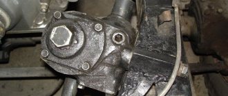
Transfer case for UAZ-452 cars
The transfer case (transfer case) of the UAZ-452 is designed to transmit torque to the front and rear axles and has two gears: direct with a gear ratio of 1.00 and a reduction gear with a gear ratio of 1.94.
Fig.1. Transfer case (transfer case) UAZ-452
1 — driven shaft of the gearbox; 2 — driven shaft bearing; 3 — gear for downshifting and rear axle; 4 and 7 — rear axle drive shaft bearings; 5— driven gear of the speedometer drive; 6 — speedometer drive gear; 8 - cover; 9 — rear propeller shaft flange; 10 — rear axle drive shaft; 11 and 24 - intermediate shaft bearings; 12 — intermediate shaft; 13 — front axle engagement gears; 14 — bridge cover; 15— front axle drive shaft; 16 — front shaft drive bearings, 17 — crankcase cover, 18 — crankcase gasket; 19 — transfer case housing, 20 — plug; 21 - cover; 22 — oil seal; 23 — front driveshaft flange; 25— plug; 26 — bearing cup; 27—box cover; 28—switching mechanism cover, 30—breather; 29 - upper crankcase hatch cover, 31 - oil filler plug The reduction gear allows you to significantly increase the traction force on the wheels under difficult operating conditions of the vehicle (off-road, deep snow, climbs). The UAZ-452 transfer case is shown in Fig. 1. The drive shaft of the transfer case is the driven shaft 1 of the gearbox included in it. The sliding gear 3 for engaging the rear axle and downshift is installed on the splines of this shaft. When this gear moves backward and connects it with the internal teeth of the rear axle drive shaft 10 gear, the rear axle will be engaged (gear ratio 1.00), and when it is moved forward and engaged with the intermediate shaft gear 12, a downshift will be engaged (gear ratio 1, 94). The intermediate shaft of the UAZ-452 transfer case, made integral with the reduction gear, rotates on two bearings, the front of which is roller, and the rear is ball. The sliding gear 13 for engaging the front axle moves along the splines of the transfer case shaft. When moving backward along the splines, this gear meshes with the gear of shaft 15 of the front axle drive. Both shafts are mounted on ball bearings. All UAZ-452 transfer case shafts are protected from axial movements by bearing caps and thrust rings installed in the grooves of the outer rings of ball bearings. The drive gear 6 for the speedometer drive is installed on the rear axle drive shaft. All gears of the UAZ-452 transfer case are straight-cut. When assembled at the factory, the gears are selected for noise. If for some reason during operation one of the gears is replaced with a new one, then such a transfer case may experience slightly increased noise during operation. Such noise is acceptable and is not dangerous for the transfer case. The bearings of the UAZ-452 transfer case do not require any adjustment in operation.
Fig.2. Transfer case control mechanism UAZ-452 1 — front axle engagement lever; 2 - lever for engaging the rear axle and downshifting in the transfer case; 3 — shaft for engaging the rear axle and downshift; 4 — front axle activation shaft; 5 - cracker; 6 — spherical bushing; 7 — spherical bushing body; 8 and 9 — intermediate levers; 10 — adjusting rods; 11 — front axle engagement rod; 12 — rod for engaging the rear axle and downshift in the transfer case; 13 - protective cuff Control of the transfer case of UAZ-452 vehicles, shown in Fig. 2, is remote. The control levers are located to the right of the driver, in front of the engine hood. The upper lever 1 is used to turn the front axle on and off and has two positions: forward when the front axle is turned on, and rear when the axle is turned off. Lower lever 2 is designed to change gears in the transfer case of the UAZ-452. It can be installed in three positions: forward when direct gear is engaged, neutral (middle) position in which the driven shaft does not rotate, and rear when downshift is engaged. Due to the presence of a locking device (lock) installed in the cover of the gearshift rods, a downshift can only be engaged after the front axle is turned on, and the front axle cannot be turned off when the downshift is engaged. Figure 3 shows the lock and the position of the rods when engaging the gears and the front axle.
Fig.3. Lock of the switching rods of the UAZ-452 transfer case a - position of the rods when engaging direct transmission (rear axle); b — position of the rods when downshifting and the front axle are engaged; 1 — front axle switch lever; 2—lever mounting pin; 3 — rod of the front axle activation lever; 4 — lever for downshift and rear axle; 5 — ball-lock; 6 — cover of the switching mechanism; 7—rod of the downshift lever and rear axle Figure 3a shows the position of the UAZ-452 transfer case rods when the rear axle is engaged (rod 7) and the front axle is disengaged (rod 3). At the position shown in Fig. 3b - the rods have moved to a position in which the front axle is engaged by rod 3, and downshift is engaged by rod 7. The locking ball 5 installed in the cover does not allow moving the rod 3 and disabling the front axle until the downshift is turned off by the rod 7. The lock is designed to prevent overloading of the driveshaft and rear axle parts. The front axle should be engaged when driving on a difficult road (mud, sand, snow, etc.). It is not allowed to engage the front drive axle when the front wheels are disabled. The position of the UAZ-452 transfer case shift levers is shown in Fig. 4.
Fig.4. Diagram of the position of the shift levers of the UAZ-452 transfer case a - front axle (upper lever); b — gear shift (lower lever); I—direct transmission; II - neutral position; III - reduction gear The spherical bushing 6 (see Fig. 3) of the upper shaft support and the bushing of the intermediate lever axis are made of plastic I and do not require lubrication. The lower ball joint is filled with graphite grease during assembly and additionally lubricated only during repairs or if squeaking occurs.
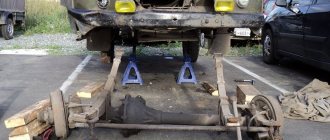
Front control rods 10 are adjusted in length using threaded forks. To adjust the position of levers 1 and 2, unpin and remove the finger from the rod fork connected to lever 1; set the rod (in the transfer case cover of the UAZ-452) to the rear axle engagement position, and lever 1 to the position corresponding to this gear. By rotating the fork, set the required rod length, align the holes in the rod fork and the lever, insert a pin and pin it. The position of lever 2 is adjusted in the same way. During the first maintenance (TO-1), the UAZ-452 transfer case housing is checked by inspection; If traces of grease are found on it, check the oil level and eliminate the problem. The oil level should be located at the lower edge of the filler hole. When refueling, do not rotate the shafts, as oil will stick to the gears and enter the crankcase in more quantities than required. This may cause oil to leak through the seal while the vehicle is running. At TO-1, check the oil level in the transfer case housing and, if necessary, top up. During the second maintenance of the UAZ-452 transfer case (TO-2): - Inspect the tightness, condition and fastening of the UAZ-452 transfer case and its drive. Remove the propeller shafts and tighten the nuts securing the flanges on the transfer case shafts (front and rear). Tighten the nuts and replace the driveshafts. When cottering, it is not allowed to unscrew the nut to ensure that the slot on it coincides with the hole on the shaft. To do this, you just need to tighten the nut. Clean the breather from dust and dirt and blow it out. Change the oil in the crankcase. If the oil is heavily contaminated or there are metal particles in it, the crankcase should be flushed with kerosene before adding fresh oil. To do this, you need to pour 0.8-1.0 liters of kerosene into the crankcase, raise the wheels, start the engine and let it run for 2-3 minutes, after which the kerosene is drained and fresh oil is added.
______________________________________________________________________________
______________________________________________________________________________
- Clutch and gearbox UAZ Hunter
- Transfer case and driveshafts UAZ Hunter
- Drive axles UAZ Hunter
- Adjusting the steering mechanism of the UAZ Hunter
______________________________________________________________________________
______________________________________________________________________________
- Checkpoint UAZ-Patriot
- Razdatka UAZ-Patriot
- Drive axles UAZ-Patriot
- UAZ-Patriot suspension
- Steering UAZ-Patriot
- UAZ Patriot power steering faults and their elimination
- Components of the UAZ-Patriot hydraulic brake drive
- UAZ-469 engine and its main parts
- Gearbox UAZ-469
- Drive front and rear axles of UAZ-469
- Clutch of UAZ-469 cars
______________________________________________________________________________
- Cylinder block and timing belt for UAZ-31512, 31514 engines
- Front and rear suspensions UAZ-31512, 31514
- Operations for assembly and disassembly of UAZ-31512, 31514 bridges
- Steering UAZ-31512, 31514 and its parts
- Brake system UAZ-31512, 31514
- Gearbox UAZ-452
- UAZ-452 clutch and its parts
- Transfer case UAZ-452
- UAZ-452 bridges and its components
- Gearbox UAZ-3909, UAZ-2206
- Cardan transmission UAZ-3909, UAZ-2206
- Front axle UAZ-3909, UAZ-2206
- Brakes UAZ-3909, UAZ-2206
- Clutch UAZ-3303
- Transfer case UAZ-3303
- Rear axle UAZ-3303
- Steering of UAZ-3303
- Cylinder block and crankshaft ZMZ-409
- Timing belt and valves ZMZ-409
- Lubrication system ZMZ-409
- Cooling and power system ZMZ-409
- Parts of the UMZ-421, UMZ-4218 cylinder block
- Timing belt and valves UMZ-421, UMZ-4218
- Lubrication system UMZ-421, UMZ-4218
- Cooling system UMZ-421, UMZ-4218
- Fuel system UMZ-421, UMZ-4218
UAZ Bukhanka transfer case control
The UAZ Bukhanka transfer case is controlled remotely from the driver’s cab. The levers used to manipulate the car are located on the right side of the user. The upper rod activates and deactivates the front pair of wheels of the car, has two positions: top (the bridge is activated), bottom (the bridge is deactivated).
Position of the transfer case levers of the UAZ Bukhanka:
The location of the transfer case levers on the UAZ Bukhanka is possible in three options. First, the main gear is activated, middle (zero), the main shaft does not rotate, second, low gear is activated.
In order to avoid damage to the transfer case if the gear is incorrectly activated, a locking device is provided. The product is fixed in the cover of the gear change rods. Thanks to the fuse, the low gear is activated after the front pair of wheels is activated. Meanwhile, the front pair of wheels is not activated when a downshift is engaged. A solution has been implemented with a ball acting as a lock. The sphere in the cover prevents the rods from moving and deactivates the front pair of wheels until the rods are put into downshift. The lock prevents the driveshaft and rear pair of wheels from being overloaded.
There are single-lever control elements, one rod alternately activates: the front pair of wheels, zero, then low stage.
The UAZ-452 was originally created for the Soviet armed forces as a medical service vehicle, where it was therefore dubbed the “tablet” (the civilian nickname is “loaf”).
Therefore, the design of the mechanisms, including the transfer case, is simplified as much as possible.
During operation, the entire transmission system is unpretentious, which is confirmed by half a century of practice. The only recommendation from the manufacturer is to periodically check the oil level and check the fasteners.
In addition, if necessary, the front linkages should be adjusted and the lever axles should be lubricated on a preventive basis. This mechanical unit, including bearings, does not require any further maintenance or adjustment.
Transfer case control
Both levers are located in the cabin on the right side of the driver.
The top one is designed for remote control of the front axle and is fixed in 2 positions - rear (when the drive is turned off) and front (when the drive is on). The “loaf” front axle is used only when driving a car in difficult conditions. “Turn off the front axle when driving on dry, hard roads!” is attached to the “dashboard” in front of the levers
The lower one drives the range multiplier (which in the auto industry is also called a divider). The fact is that in a UAZ, as in any all-terrain vehicle or off-road vehicle, gear shifting is provided not only in the gearbox, but also in the transfer case.
For the latter, there are 3 positions - reverse (with low gear engaged), middle or neutral (in which the shaft is not connected), forward (with direct gear engaged).
The lower stage can only be used after moving to the front axle. It, in turn, cannot be turned off when the reduced stage is operating.
3.9 / 5 ( 52 voices)
Turning on all-wheel drive on a UAZ Patriot
UAZ vehicles assembled before 2013 have a standard transfer case. To change operating modes, a separate lever is used, located on the tunnel between the front seats. The handle allows you to turn the drive to the front axle on or off, as well as select direct or reduced speed in the gearbox. A spherical plate is mounted on the handle, on which the gearbox switching algorithm is indicated.
After the introduction of the Hyundai Dymos transfer gearbox (developed in South Korea), a rotary washer mounted on the center console is used to switch transmission modes.
Operating modes of the Dymos gearbox:
- Standard 2H, used when operating a vehicle on highways or dirt roads with hard surfaces (in summer and winter).
- All-wheel drive mode with direct 4H transmission, activated when driving on wet or slippery dirt or asphalt roads. When the drive is turned on, a control indicator on the instrument panel is activated. The factory recommends switching the mode only when driving in a straight line. Activation of the drive on 2 axles when moving in an arc leads to shock loads on the transmission units. If, when turning the washer, the drive to the front axle does not turn on, then you need to increase or decrease the speed and then try again.
- The lowered row 4L is used when driving in difficult road conditions or when moving a trailer through mud or deep snow (up to 400 mm or more). The mode provides an increase in torque at the wheels; a warning lamp lights up on the instrument cluster. When driving, it is forbidden to jerk the car sharply with the engine, since the chain mechanism does not tolerate shock loads and is destroyed.
When all-wheel drive is connected, the gearbox may produce extraneous sounds accompanied by body vibration. When operating a vehicle with front axle drive, controllability deteriorates (the angle of rotation of the wheels decreases), and vibrations occur when the steering wheel rotates. The use of the drive on dry roads leads to increased fuel consumption and additional noise, and also negatively affects the service life of tires and transmission components.
To return to rear-wheel drive mode, you need to release the gas pedal and then press the clutch. At the same time, the washer is rotated to the 2H position. After the 4H indicator goes out on the instrument cluster display, the clutch pedal is released. To shift from a lower gear to a direct gear, you need to stop the car, then press the clutch pedal, then move the washer from position 4L to position 4H, wait until the indicator turns off and release the clutch.
When operating machines with a Dymos gearbox, a malfunction occurs due to spontaneous activation of the all-wheel drive. The defect is associated with erroneous switching of the unit control unit.
To restore functionality, you will need to repair the controller or replace the part along with the rotary washer. The design of the gearbox provides a diagnostic system: when faults are detected, the 4WD Check indicator turns on in the instrument cluster with simultaneous activation of the indicator of the operating mode in which the problem was detected.
Shift levers for UAZ loaf. The legendary UAZ loaf. Tuning, repair
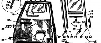
CONTROLS OF VEHICLES OF THE UAZ FAMILY - 3741 I Instrument panel 2. Cover of the hydraulic clutch master cylinder reservoir hatch 3. Steering wheel 4. Horn button 5. Turn signal switch lever 6. Sun visor 7. Cabin canopy 8. Passenger handrail 9. Mirror scarlet rear view 10 Door lock handle II Window lifter handle 12. Ashtray B. Gear shift lever I. Front axle shift lever. Has 2 positions: front - axle is on, rear - axle is off 15. Lever for engaging direct and downshift gears of the transfer case. Their Radiator shutter drive handle 17. Carburetor air damper control handle. Fixed by turning 90° in any direction 1& Carburetor throttle control knob. Fixed by turning 90” in any direction 19. Driver’s seat 20. Battery ground switch 2L Fuel tank switch. It has three positions: turned to the right - the right (additional) fuel tank is turned on; turned forward - the tap is closed; turned to the left - the left (main) fuel tank is turned on. (On vehicles UAE-39091 the crane is not installed) 22. Brake system lever 23. Carburetor throttle pedal 24. Brake pedal 25. Clutch pedal 26. Foot light switch 27. Plug socket 28. Fuse block 29. Thermal fuse button in lighting circuits 30. Heater fan motor switch 31. Central light switch. It has three positions: first - everything is off, second - side lights are on, third - side lights and low or high beam are on (depending on the position of the foot light switch) 32. Ignition switch. Has four key positions: 0 - neutral, I - ignition on, II - ignition and starter on, III - receiver on (if installed) 33. Warning light for emergency overheating of the coolant 34. Warning light for emergency oil pressure in the engine lubrication system 35 . Indicator lamp for hydraulic brake control (red) 36. Turn signal lamp (green) 37. High beam signal lamp 38. Windshield wiper switch (by rotating the handle) and washer switch (by pressing the handle in the axial direction) 39. Hazard warning switch 40. Speedometer with totalizing trip meter 4L Voltmeter. Shows the voltage in the vehicle's on-board network 42. Oil pressure indicator in the engine lubrication system 43. Parking brake indicator lamp (red) 44. Coolant temperature indicator in the engine cylinder block 45. Fuel level indicator in the left tank I. Key position in ignition switch P. Position diagram of gearbox levers and transfer case levers
And for some reason, even the steering wheel is old and hard
Although on the passenger line (,), the steering wheel is installed “soft”, two-spoke. True, that line still includes power steering and ABS! So, apparently, this configuration