UAZ 3741 is an all-wheel drive domestic utility vehicle, which in Soviet times was produced under the symbol UAZ 452 and is called “Loaf” for its characteristic body shape. In the factory configuration, the car has an all-metal body, as well as a spring suspension and two drive axles with non-locking differentials that transmit power to all four wheels.
Front-wheel drive is plug-in, rear-wheel drive is permanent. The bridges are unified with model 31512. Loaf capacity is 850 kg. The ground clearance is 22 cm. Repair of the front axle 3741 is required extremely rarely, since its design is quite reliable. Basically, the repair comes down to replacing the wheel bearings, as well as oil in the differential, king pins and ball bearings. However, sometimes it is still necessary to remove the bridge. You have to do this yourself, since UAZ service centers do not operate everywhere.
Removing a faulty unit
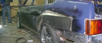
Since the UAZ 3741 has a frame structure, the front axle can be removed quite easily. To do this, you need to stock up on a powerful jack, stops that can support 1.5 tons of the front of the car, and WD-40 - a liquid for loosening nuts.
The procedure is as follows:
- First you need to install chocks under the rear wheels of the car.
- After this, you should disconnect the left and right brake pipes from the hoses going to the front wheel drums.
- Then you need to unscrew the nuts securing the brake hoses and remove the hoses themselves.
- Next, unscrew the nuts securing the lower ends of the shock absorbers.
- Remove the bolts connecting the drive gear flange to. front driveshaft.
- Then you should undo the cotter pin and unscrew the bipod ball pin nut.
- Disconnect the rod from the bipod.
- Unscrew the nuts that secure the front spring stepladders and remove the stepladders with pads and pads.
- At the end, you need to lift the front of the car by the frame and pull the bridge out from under the car.
When the old bridge is removed, you can proceed to installing a new part by performing the reverse procedure. If necessary, the removed unit is disassembled, troubleshooting is carried out, damaged parts are replaced, and then the bridge is returned to its place.
Replacing the axle shaft seal of a UAZ loaf
Step-by-step instruction:
- Jack up, remove the rear wheel and brake pads.
- Using a 14 mm socket, through the large hole in the axle shaft flange, unscrew the four bolts securing the axle shaft and brake shield plates to the rear axle beam flange. Remove the bolts with spring washers.
- Using a Phillips screwdriver, unscrew the two screws securing the shield to the axle plate. Pass an M8 bolt through its hole and insert it into the hole in the beam flange. The shield is temporarily suspended.
- Rotate the axle plate, screw two M12×1.25 bolts into the wheel mounting holes located diametrically until they stop at the brake shield next to the holes in the beam flange.
- Tightening the bolts one by one, press out and remove the axle shaft.
- Pry the oil seal with a pry bar or a metal screwdriver and remove it from its normal place.
Press in the new oil seal with a piece of pipe of the appropriate diameter, lightly tapping its end with a hammer. Reassemble all parts in reverse order. Check the oil seal for leaks.
- Home
- Auto garage
- Replacing the Front Axle Axle Seal of the UAZ Bukhanka
Any motorist can repair the front axle of a UAZ Bukhanka and UAZ 469 on his own. This job is easy. Structurally, both of these models are identical. This is especially true for the suspension. The frame design allows for easy dismantling of the front axle and the highest reliability of the vehicle. There are some differences in leaf spring and spring suspension. However, these features have little impact on the complexity of the work.
During repairs, discs or cassettes, special tools, are actually not useful. The work is performed with the smallest set of tools available to each driver.
Repairing the front axle of UAZ Bukhanka and UAZ 469 at home is not difficult. In most cases, during operation it is necessary to carry out various preventive works. Typically, they do not require removal and disassembly of the bridge. The list of actions for care includes:
- The kingpins are checked for gaps;
- Threaded connections need to be tightened from time to time;
- The alignment is checked;
- Prescriptions for parts lubrication tables are made.
It is imperative to visually inspect the main components. Increased attention is paid to the serviceability of the fastening bolts. They are also firmly reinforced, so it remains for our client to make the locking elements. Inspect the maximum turning angle of the wheels. It should not exceed 28 degrees. If indicators differ from those indicated, it is necessary to make adjustments. Also always check that the kingpins are tightened and functioning correctly. Failure to eliminate small defects in a timely manner leads to the need for major repairs of the front axle.
Repair of this unit begins with dismantling the bridge. On a loaf and a goat, this construction is carried out identically. There are only small differences. When performing repairs, you must be as careful as possible. Removing the bridge involves a series of easy steps:
- You should start by ensuring that the car is stationary. For this purpose, anti-roll brake pads are installed;
- Next, on the goat, the brake pipes are disconnected from the hoses. On the Bukhanka, the tubes have adapter pipes. In this case, the hoses are disconnected from the pipes;
- Remove the nuts securing the lower shock absorber cups. This element is similar on both machines.
- Next, unscrew the bolts connecting the drive gear flange and the front driveshaft. Before this, you need to fill the threaded connection with WD-40;
- Remove the rod from the bipod. The nut located on the ball pin is twisted;
- Tighten the nuts that secure the spring ladders. They disassemble them with linings;
- The front of the car is jacked up by the frame and the bridge is rolled out.
Correcting wheel axial play
Most often, the reason for the car’s inappropriate behavior on the road is a violation of the axial clearance of the king pins. It is very easy to check if it is broken - just lift the front end with a jack and rock the wheel up and down. When axial play is detected, the kingpin clearance needs to be adjusted.
Adjustment steps:
- We raise the front of the car, having previously placed the car on the handbrake.
- We dismantle the wheel.
- Unscrew the ball bolts securing the oil seal.
- We check the axial play by rocking the structure up and down.
- Unscrew several bolts of the upper king pin cover and remove the cover.
- We take out the thinnest gasket and put the lining back.
- We perform the same actions with the lower lining of the king pin.
- Tighten the bolts and check the result. When the play is eliminated, screw the wheel and seal back on and off we go. If the play remains, we adjust it again, removing thicker gaskets.
Many Internet users enter a similar request in Yandex or Google - “repair of the front axle of UAZ 469”. This means that they are interested in how to repair the front or rear axle on a UAZ themselves. Of course, the procedure for dismantling and repairing the bridge is described in special books on repair and operation, which are now not a problem to obtain. However, disassembling with your own hands both the front and rear axles down to the last screw is, to put it mildly, not an easy task. It may turn out that you just need to replace some small part, to access which you don’t have to disassemble everything.
Front axle UAZ 469
Here are just some possible options for bridge failures on the UAZ 469 (Hunter, Patriot, “loaf”):
- The differential is worn out, the gear housing is bent
- Critical wear of the main gear in the gearbox
- Wear of the steering knuckle (ball joint, axle) on the front axle
- The appearance of large gaps in the pivot joints
- Bearing wear, resulting in the need for adjustment or replacement
- Injection of elements requiring lubrication
It can be difficult to understand which of the above happened to your car, however, it is often possible to roughly localize the problem even by ear. If you hear increased noise or a hum from the front or rear axle (even in neutral gear), the gearbox is most likely worn out (needs repair), or the bearings require lubrication. If your car “yaws” from side to side and the steering is fine, the problem may be stuck in the axle, CV joint, or incorrect installation of the pins that secure the ball joint, as a result of which play appears and the wheel begins to “walk.”
What does a CV joint consist of?
A very common malfunction is the flyout of the ball bearings that are located in the CV joint. They fly out precisely because of incorrect adjustment of the pins, as a result of which the geometric center of the CV joint and the axle do not coincide. As a result, the axle shaft “walks” in the seat and gradually breaks down. The CV joint itself is also damaged. And when turning, you can hear a crunching sound from the side of the wheel and the wheel may jam. During the repair process, some craftsmen simply throw out all the balls, except for the centering one (additionally welding it) - in order to get rid of the problem of their constant flying out.
Steering knuckle of the front axle UAZ 469 assembled
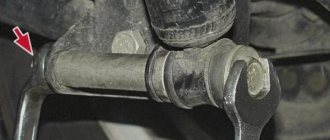
But this does not save for long; there are even cases when the welded ball breaks off while driving, the loads there are so high. It is much more effective to adjust the king pins. It is necessary to achieve a condition in which the line passing through the king pins and the center of the axle shaft intersect at one point. And it is at this point that the center of the CV joint should be located. The displacement of the axle shaft from left to right, as shown in the figure, is unacceptable; it must be rigidly fixed; for this purpose, thrust rings and bushings are provided in the design.
Dismantling and defect detection of the rear axle of UAZ-3151
Disassemble the bridge in the following order:
1. Place the bridge on the stand (Fig. 1), unscrew the oil filler and oil drain plugs and drain the oil.
Rice. 1. Installation of the bridge on the stand
2. Unscrew the bolts securing the axle shafts and, using them, remove the axle shafts.
3. Unscrew the nuts and bolts securing the cover and crankcase, and carefully separate the bridge into two parts. Remove the gasket.
4. Remove the differential and driven gear assembly from the housing.
5. Remove the main drive gear.
Without disassembling the axle, it is impossible to remove the drive gear, since when pressing the gear and bearing assembly out of the axle housing, the rear bearing (with cylindrical rollers) will rest against the driven gear.
Rice. 2. Pressing out the drive gear
To remove the drive gear, unscrew and unscrew the nut on the shank, remove the washer and flange, unscrew the bolts and remove the drive gear front bearing cap.
Remove the oil removal ring and use a tool to press the drive gear (Fig. 2) with the bearing assembly out of the crankcase.
6. Disassemble the differential in the following order:
– Unscrew the bolts securing the driven gear to the satellite box; remove the driven gear;
– unscrew the bolts securing the halves of the satellite box;
– disconnect the right half of the gearbox from the left and remove the differential gears, satellite axles and support washers.
Assessment of the technical condition of parts
After disassembling the bridge, thoroughly rinse the parts in kerosene and inspect.
Replace gears with scoring and chipping on the teeth.
Replace bearings that are worn. If the bearings and associated parts do not require replacement, then do not press out the bearing rings.
Press out the outer rings of the bearings (Fig. 3) of the differential from the crankcase and cover and remove the inner rings (Fig. 4) of these bearings using tools.
Removal of the rear and front drive gear bearings is shown in Fig. 5 and 6.
The end of the neck on which the rear bearing is pressed is open, therefore, press it out only for replacement.
When disassembling the axle, do not disassemble the inner and outer rings of the differential and drive gear bearings, and when reassembling, install the bearings that do not need to be replaced in their original places.
The oil removal ring must have smooth ends.
If necessary, sand it to a thickness of at least 5 mm.
Cardan flange
The end of the flange associated with the oil removal ring must be smooth. If necessary, sand it to a height of at least 53 mm.
Rice. 3. Pressing out the outer ring of the differential bearing
Rice. 4. Removing the inner race of the differential bearing
Rice. 5. Removing the rear bearing from the drive gear
Rice. 6. Removing the front bearing from the drive gear
Bridge housing
Remove all roughness and burrs from the seating and adjacent surfaces of the crankcase.
Clean the oil channels.
Differentials and axle shafts
Replace thrust washers, pinion axles, pinions, axle gears and pinion boxes with scoring and severe wear.
Replace satellites and semi-axial gears as a set.
Replace the side gear thrust washer if its thickness is less than 1.2 mm.
If the ends of the satellite box are worn, it is permissible to install washers increased in thickness by 0.1 mm or 0.2 mm.
Adjustment
Before you start adjusting, prepare everything you need: bushings for the axle (if there is a groove on the axle), 4 thrust bushings, as well as oil seals. The main condition for adjustment is that the two halves of the CV joint do not dangle, both during straight-line movement and when turning! The procedure is as follows:
- Take the ball joint and press the bushing into it so that half of the CV joint does not hang out in the ball joint.
- There is a thrust washer on top; be sure to install a new one, even if the old one appears to be in good condition.
- Take a metal shaft (you can make it from a valve, for example) with cones on both sides and put a washer on it with a diameter similar to the central ball, that is, 27 mm. Place one edge against the center of the kingpin. Ideally, the second edge should also be in the center of the kingpin. If this is not the case, place the adjusting washers in the same place where the thrust washers are, or rather, under it.
Adjustment
- It is necessary to try on the steering knuckle body over the ball joint and make sure that the center of the large hole in the steering knuckle coincides with the center of the support. If it is shifted by at least 3 mm, the CV joint cannot be assembled, since there is already a bushing there. And to adjust in the center, place a certain number of adjusting washers under the left or right kingpin, depending on which direction and how many mm you need to move the central axis.
- The kingpin must be tightened so that by hand you can turn the ball joint back and forth. If the seat for the king pin is broken and the king pin rotates together with the ball, grind off a few millimeters on the king pin and install it through the bushing. Rotation or play is unacceptable, since they lead to rapid wear of both the kingpin and the seat under it.
- It is better to replace the bushing in the axle itself (both front and rear). If necessary, adjust the size using a reamer. It is important to note that each half of the CV joint needs to be done differently. There shouldn’t be any play, but if half of the CV joint is too tight, then it’s better to remove it with a larger reamer.
- It is extremely important that the bushings are in place as shown in the image. If you place the bushing on only one side, then when the wheel turns, most of the load will fall on it, as a result - rapid wear, the appearance of play, and then the CV joint needs to be replaced.
Bronze bushings should be located in these places
During the assembly process after repair, it is necessary to lubricate all the bolts with nigrol so that next time everything can be easily unscrewed. All mating surfaces (the junction of the axle and the steering knuckle housing) must be cleaned of dirt. It is not recommended to lubricate the CV joint with grease, as it is thick. When heated under the influence of centrifugal force, all the solid oil will be scattered over the walls of the ball joint, and it is necessary that the CV joint balls be generously lubricated. To do this, it is recommended to dilute the solid oil by half with nigrol.
After final assembly and repair, one more important adjustment needs to be made. We are talking about an adjusting rotary bolt. This is the bolt that limits the maximum angle of rotation of the wheel. It is important not to overdo it; do not tighten the bolt all the way - otherwise the wheel will jam. Tighten almost to the end, and then try to turn the wheel (more precisely, the shaft on which it will stand). It is necessary to unscrew the bolt back until the wheel stops wedging. The rotation angle should be no lower than the factory one. Well, now you yourself can repair the front axle on the 469 UAZ!
UAZ is a common car on Russian roads. Its design features allow you to move without problems on paved areas, as well as off-road. Repairing the front axle of a UAZ is impossible without knowing the diagram of the wheel gearbox, the design of which is similar to a similar part of the rear axle. The key difference is the peculiarity of fastening and installation of the main gear, the design parameters of the ball bearing located in a special compartment-cup.
Disassembly and assembly of final drive
Disassemble the final drive in the following order:
- After removing the hub with the brake drum (see the section “Removing, disassembling and assembling hubs”), unscrew the clutch of the brake drive pipeline on the rear brake shield (on the front there is a tee of connecting tubes and a flexible hose) from the wheel cylinder, unscrew the nuts of the axle mounting studs and Remove the spring washers, oil slinger, axle, axle gasket, spring spacer, brake assembly and brake shield gaskets.
- Unscrew nut 45 (see Fig. 188) securing the bearing to the final drive driven shaft, unscrew the bolts securing the final drive housing cover, remove the cover assembled with the shaft, remove the cover gasket and press the shaft out of the cover. Unlike the left final drive, shaft 39 and nut 45 of the right gear have a left-hand thread. The nut with a left-hand thread is marked with an annular groove, and the shaft is marked with a blind drilling with a diameter of 3 mm in the end of the splined end.
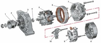
Rice. 188. Rear axle with final drive: 1-main gear housing cover; 2-differential bearing; 3,13,49-adjusting shims; 4-sealing gasket; 5.7-drive gear bearings; 6.15-adjusting rings; 8.42-cuffs; 9-flange; 10-nut; 11-dirt deflector; 12-ring; 14-spacer sleeve; 16-drive main gear; 17-satellite; 18-right axle shaft; 19 final drive housing; 20,29-oil deflector, 21-axle bearing; 22,26,40-circlips; 23-sealing gasket for final drive housing; 24-final drive housing cover; 25-bearing; 27-brake shield; 28-brake drum; 30-bolt wheel fastening; 31-trunnion; 32-hub bearing; 33.41-gaskets; 34-lock washer; 35-drive flange; 36-nut wheel bearings; 37 lock washer; 38-bushing; 39-driven final drive shaft; 43-driven shaft bearing; 44-driven final drive gear; 45-special nut; 46.50 - drain plugs; 47-drive final drive gear; 48 right cup of the satellite box; 51-main gear housing; 52-axle gear washer; 53-axle gear; 54-axis satellites; 55-driven final drive gear; 56-left satellite box cup; 57-left axle shaft
- Unscrew the driven gear mounting bolts and remove the gear from shaft 39.
- Mark the position of the roller bearing housing 25 on the final drive housing boss of the rear axle, unscrew the housing mounting bolts, and remove the bearing housing. Do not remove the front axle final drive roller bearing housing unless absolutely necessary. (For further procedure for disassembling the final drive of the front axle, see above in the description of replacing the grease in the steering knuckle joints). Remove the retaining ring 22 of the ball bearing 21, the axle shaft 18 and the oil deflector 20 from the final drive housing.
- Remove the roller bearing retaining ring 26, roller bearing 25, drive gear 47 and ball bearing from the axle shaft.
Assemble the final drive in the reverse order of disassembly, taking into account the following: bearing mounting nut 45 (Fig. 188) on the driven shaft of the front and rear final drives, as well as nut 19 (see Fig. 189) securing the bearing and gear on the front drive shaft After tightening, expand the final drive into the groove of the shaft, and crimp the bearing locking rings 26 on the axle shafts of the rear final drives after installation into the groove; Tighten the bolts for fastening the wheel (driven gear) and the removable bearing housing to a torque of 64 -78 N*m (6.5-8.0 kgf*m), bolts for fastening the crankcase cover - 35-39 N*m (3.6-4. 0 kgf*m).
Rice. 189. Front axle steering knuckle with final drive: a-signal groove; b-index; I-right steering knuckle; II-left steering knuckle; III-wheel release clutch (for an alternative design, see Fig. 180, IV); 1-oil seal; 2-ball joint; 3-knuckle joint; 4-gasket; 5-press grease fitting; 6-pin; 7-overlay; 8-steering knuckle housing; 9-pin bushing; 10-bearing; 11-driven final drive shaft; 12-hub; 13-drive flange; 14-clutch; 15-ball retainer; 16-protective cap; 17-bolt coupling; 18-trunnion; 19-lock nut; 20, 23-support washers; 21-drive final drive gear; 22-stop pin; 24-ring rubber sealing; 25-thrust washer; 26-axle housing; 27-bolt rotation limitation; 28-stop-wheel rotation limiter; 29-lever knuckle
Device and characteristics
The design of the UAZ front axle in older models has few differences from the similar design in new models (Spicer). The main differences lie in the design of the crankcase, the dimensions of the components of the drive gear and differential, and in a number of units used.
The design of the old model is in many ways similar to the rear axle of the UAZ and consists of the following components:
- The key place is occupied by the split crankcase, consisting of 2 separate parts.
- Each half is equipped with press-in housings with internal axle shafts.
- Safety valves on the casings, responsible for controlling the growth of oil volume in the mechanism.
- The differential and main gear of the casing are made according to the standard design: a small-diameter drive gear is located in the horizontal plane, in contact with the cardan.
- The large driven gear in the longitudinal plane is in mesh with the main gear. It has a built-in differential of 4 satellites.
- The edges of the crankcase housing are equipped with pivot joints made of ball joints with a rotating housing.
Repair of the rear axle of UAZ 469: main difficulties and overcoming them
Repair of the rear axle of the UAZ 469 is rarely required - it is a reliable component designed for large multidirectional loads. But nothing is impossible for an SUV. The basis for failure may be intensive use, insufficient maintenance, or failure to overcome obstacles.
General design description and hazards
It provides body support and connects the wheels to the transmission. In addition, it installs several devices that are important for use:
- Differential. It also belongs to the transmission system. Necessary for the drive wheels to rotate independently of each other.
- Main drive of the axle shaft.
- Wheel adjusters installed on the edges. Thanks to them, there is a rapid and significant increase in torque.
Generally speaking, from the point of view of repair work, this is a compact arrangement of mechanical units with a predominant gear engagement. Therefore, typical problems are:
- Incorrect adjustment of one of the gears, causing the wheel part to work inconsistently or rotation to be transmitted and transformed incorrectly. This can only be eliminated by disassembling and adjusting.
- Worn bearings, axles or gears. In this case, it is preferable to replace the component with an identical one. Spare parts for UAZ Hunter can always be purchased for any modernization. This is one of the main advantages of domestic inexpensive vehicles.
- Oil leaks. To minimize friction, a lubricating fluid has to be poured inside, which, moreover, cools the components of the assembly. If the seal is damaged, it leaks and the mechanisms begin to destroy themselves (wear accelerates significantly). Leaks are detected by characteristic traces.
- Fracture of the case caused by natural abrasion, serious impact, or rust. Here, restoration in a workshop is acceptable.
Regardless of the reason, dismantling is indicated, which requires appropriate technical equipment and tools. Without experience, it’s better not to even approach the rear axle. Gears are a complex thing, and it’s easy to get confused in them if you don’t have a deep understanding. In addition, a comprehensive diagnosis has many subtleties that should not be missed.
Any UAZ repair in Tver by specialized companies allows you to speed up the process and not doubt its results. It is worth contacting them not only when the movement of the car is no longer possible.
Carrying out preventive maintenance and early identification of non-conformities can prevent downtime and cost less. It is advisable to seek professional advice even after obvious changes in operation or after shock impacts.
Freshly produced or used
Reinstallation is fully meaningful only in case of critical deformation or when the vast majority of parts are irreparably worn out. In most situations, it turns out to be limited to local rearrangement. The customer always has a choice: install a completely new spare part or save a little and take something from a disassembled 469. Both ways are real, but the first option is much more reliable. The loads are extremely high, and it is difficult to be sure that they have not led to invisible defects that will soon reveal themselves. We are not talking about such a big difference that it provides significant savings.
The prospect of repairing the rear axle of the UAZ 469 should not be very alarming and, even more so, should prompt one to abandon the equipment. Proper execution makes it possible to return the original characteristics close to factory ones.
How to turn on the front axle on a UAZ
Engaging the front gear may be necessary if it is necessary to turn from an asphalt road surface onto a country road or terrain with potholes and mud. In the new conditions, rear-wheel drive will not cope with difficulties. Engaged front-wheel drive is a means of solving the problem.
System startup sequence:
- Stop the car and check the operation of the front wheel quick release clutch. It is turned on by turning the wheels clockwise until they stop.
- Move the rightmost lever forward to switch the front wheels to driving status. Now their rotation will be equivalent to the rear.
If the road condition worsens while driving, it becomes more and more difficult to continue driving, the engine stalls, you need to stop the vehicle and engage a lower gear. To do this, you will need to move the middle lever back. In low gear, all 4 speeds are available, and driving becomes easy and smooth again.
After overcoming off-road conditions, it is immediately better to put the middle lever in its original position and move the transfer gearbox to a higher level. On the highway, it is recommended to stop the front-wheel drive and quick-release clutches to save 2 liters of fuel. The measures help reduce noise levels while driving.
Malfunctions and repair work
Common malfunctions of the UAZ front axle and possible repairs:
- Leakage of lubricating fluids. Check the tubes and connecting elements for mechanical damage - the cuffs and flange for functionality, the oil container for the optimal fluid level.
- High wear of fasteners.
- Bearing defects caused by the use of poor quality material by the car plant.
- Broken axle teeth. Adjustment will not help; parts need to be replaced.
- Mechanical defects of the beam.
- Wear of elements. The situation is resolved by replacing it with new spare parts.
- Poor grip of the bearings and main gears indicates the need for tension adjustment.
Bridge repairs begin after diagnosing and searching for the cause of problems in the functioning of the mechanism, which are diverse:
- transmission components of a rear-wheel drive vehicle are faulty due to regular movement over difficult terrain;
- use of consumables and lubricants of unsuitable quality;
- Failure to monitor tire pressure can lead to shaft and bearing failures.
Most often, car owners are faced with a violation of the axial space of the kingpins and are knocked out of the required position. To diagnose, you need to jack up the front of the vehicle and move the wheel in a vertical plane. The presence of axial play indicates the need to adjust the clearance of the pins.
How to adjust bridges
You can adjust the UAZ axles yourself. This will require a number of tools and good knowledge of the mechanism. Access to the necessary parts and assemblies is possible after dismantling the structure and separating the crankcase parts. The first sign of the need to adjust the gearbox is loud noise and malfunctions of the part. Such work is required after diagnosing the condition of bridges. Adjustment includes a number of activities.
At the first stages of repair work, ensure that the nuts of the brake elements can be loosened freely. The tools you will need are a split wrench, brake fluid and a mixture of WD-40. The bridge is dismantled as follows:
- remove the fasteners between the drive gear flange and the propeller shaft;
- secure the shaft to the side;
- place the front part of the vehicle on jacks, raising the wheels above the surface;
- additionally install safety supports;
- remove the nut between the brake pipe and hose and close the hole with a plug to avoid large losses of fluid;
- after removing the lower fasteners and moving the shock absorbers from the axle, the bridge will lower;
- remove the stepladder nuts and roll out the bridge (without wheels it weighs more than 100 kg).
Repair of the most common faults
Restoring the bridge to operability is not very difficult: but it is required to be careful when performing operations. What “diseases” are most common?
Leak formation
Where the steering knuckle connects to the bridge, there is an oil seal - one of the weak points of the design in terms of lubricant leakage. The oil seal can leak oil not only due to wear, but also when the breather is clogged. If you add more lubricant than required, the result will be the same: a leak. There are two types of oil seals:
- rubber: inexpensive, but also short-lived;
- polyurethane: more expensive, have a long service life.
To replace a part, place the car on a level place and jack up the problem side, loosening the wheel nuts in advance. Further:
- remove the steering knuckle;
- clamp the part in a vice;
- pull out the oil seal by prying it with a flat screwdriver or other suitable tool;
- pull the oil seal out of the support cavity;
- Lubricate the seal before installation;
- press in the oil seal using a tube of the appropriate diameter.
- Installation is in the reverse order.
The mechanism began to hum
First of all, check the oil level. If it is normal, the bridge will have to be removed and disassembled. If the bridge hums constantly in any driving mode, the reasons may be as follows:
- incorrect setting or limiting service life of differential bearings;
- breakage (wear) of the axle shaft (its bearing);
- wear, damage, incorrect gear adjustment.
These bearings simply need to be replaced with new ones. If a humming noise appears during a sudden stop or acceleration, the reasons are as follows:
- incorrect clearance between the final drive gears;
- The final drive gear teeth do not mesh correctly.
In this case, you need to correctly adjust the gearing or replace defective parts. If the bridge hums when the UAZ enters a turn and moves in a straight line, the reasons may be the following:
- satellites rotate with great effort;
- abnormal operation of the axle gears in the differential;
- destruction, severe wear of the axle bearing;
- incorrect clearance between gears located in the differential.
To restore the functionality of the mechanism, adjust the clearances correctly and replace damaged, worn bearings. It is worth noting that the desired result when adjusting the gaps can only be achieved on a bench.
Wheel axial play
It occurs when the wheel bearings are incorrectly adjusted or when they completely fail, which is caused by over-tightening. As a result, the bearings become very hot, the smear liquefies and flows out. Algorithm of actions when performing the correct adjustment:
- Jack up the wheel on the desired side;
- Use a puller to remove the axle shaft;
- Move the lock washer to the side and unscrew the lock nut;
- Spin the wheel: if it rotates tightly, the reason may lie in jamming of the cuffs, contact of the drum and pads, etc.;
- Tighten the adjusting nut. Do this gradually while spinning the wheel. Use the WRENCH;
- Unscrew the nut about a third of a turn and install the lock washer. Tighten the nut and lock it;
- Check how the wheel rotates: it should spin freely without sticking;
- Replace the axle shaft, replace the bolts and tighten them.
You can finally check while moving. If the hub gets very hot, loosen the hub nut about 1/6 of a turn.