Repairing a generator on a VAZ 2110 car with your own hands is quite possible. You can either partially repair the element or completely replace it. It all depends on the specific situation and the degree of wear of the device.
According to the operating manual, a routine check of the condition of the generator should be carried out every 50 thousand kilometers. But this is provided that the device is working properly.
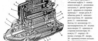
Device diagram
A set of actions for replacing and repairing a generator on a VAZ 2110 (with photos and videos)
According to the instructions, an inspection for malfunctions or replacement of the generator on a VAZ is required after the car “runs” about 50 thousand kilometers. However, in practice, sometimes things don't work out that way. For example, you notice that the alternator is not charging the battery properly, sometimes even to the point that the low voltage light on your instrument panel is on.
In this case, the VAZ 2110 generator needs to be repaired, which you can do yourself if you have enough knowledge about it. But before you start disassembling the machine parts, you need to make sure that it is the generator that needs to be repaired.
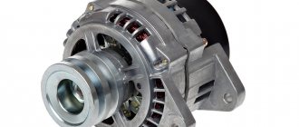
Generator VAZ 2110
Signs of a generator malfunction
The generator on the VAZ 2110 has an average resource of about 80-100 thousand km, after which failures in its operation are possible. There can be many reasons for breakdowns: generator bearings, brushes, windings, etc.
As a result of malfunctions, a weak current is supplied to the on-board network. In this case, it is important to pay attention to the following signs:
- a battery icon appears on the dashboard (indicating that the battery is not charging);
- when the lights are turned on, the headlights burn dimly or the light pulsates (unstable voltage);
- turning on additional equipment causes the dashboard backlight to dim;
- the load on the on-board network leads to the heater fan working weakly, etc.
We identify the reason
In order to carry out the test, you need to start the engine and warm it up, bring the crankshaft speed to approximately 3000 per minute. Now turn on all the lighting devices (turn the headlights to high beam) as well as the heater, windshield wiper, emergency lights, and heated glass.
If the battery voltage measurement is below 13 V, it can be assumed with a high probability that there are breaks or short circuits in the generator windings. Another reason may be a malfunction of the voltage regulator or the contact rings of the field winding have simply oxidized.
This material will help you figure out why the battery on a VAZ 2110 is discharged and cannot crank the starter: https://vazweb.ru/desyatka/elektrooborudovanie/razryazhaetsya-akkumulyator.html
Various breaks in the components of the generator can be checked if only it is removed. Do-it-yourself repairs can help in some ways, however, if the problem is serious and you do not have enough skill or driving and plumbing experience, then the best solution is to replace the failed unit assembly.
Service Features
The need to repair the generator unit on a VAZ 2112 16 valves does not arise often, but in order for the unit not to have to be repaired, it must be properly maintained. In general, this unit has a fairly high margin of reliability.
What maintenance features must be observed to prevent repairs:
- It must be remembered that the outer surfaces of the unit must always be clean.
- When carrying out maintenance, you also need to check the quality of fastening of the unit - it must be securely fixed at the installation site.
- It would be a good idea to check the functionality of the voltage regulator; a multimeter is used for this.
- The same applies to belt diagnostics. As stated above, first of all you need to check its tension - the belt should not be too tight, but it should also not be loosened. In addition, diagnostics of the condition of the strap should be carried out every 10 thousand km - there should be no signs of damage, cracks, and the belt should not peel off.
- Another point in maintenance is checking the condition of the bearings. For diagnostics, you need to remove the strap, and the rotor of the unit must be rotated by hand. If during rotation you feel a gap or even slight jamming, then the bearing devices need to be changed. The same applies to the appearance of sounds uncharacteristic of their normal operation.
Withdrawal procedure
To remove the generator on a VAZ 2110, you need to remember that correct disassembly is almost half the success. Perform actions in the following sequence:
- Drive onto an overpass or inspection hole;
- Remove the battery - it prevents you from getting to the nut securing the generator;
- Unscrew the fixing nut together with the adjustment bar using a 17mm socket wrench. To do this more successfully, try using an extension - you will have to use less effort;
- Remove the mudguard in the engine compartment;
- Remove the drive belt;
- Disconnect the wires;
- Having removed the protective cap, use a 10mm wrench to unscrew the nut securing the tip and the positive terminal of the battery;
- Unscrew the nut on the fixing bracket;
- Remove the generator by first pulling out the long bolt. Be careful not to lose the buffer bushing.
Here, in fact, the parts have been disassembled and the VAZ generator has been removed. All that remains is do-it-yourself repairs and further assembly or replacement.
How to disassemble the generator on a VAZ 2110? (Video)
Repairing a generator on a VAZ 2110 car with your own hands is quite possible. You can either partially repair the element or completely replace it. It all depends on the specific situation and the degree of wear of the device.
According to the operating manual, a routine check of the condition of the generator should be carried out every 50 thousand kilometers. But this is provided that the device is working properly.
Device diagram
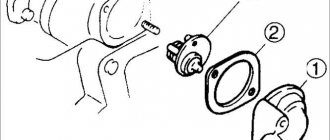
Diode bridge
It is possible to replace a damaged diode with a new one. To do this, unsolder its legs (after remembering the location of the color mark) and remove it from the plastic holder. Before installing a new diode, the contacts should be cleaned of dirt and epoxy resin. When soldering, make sure that the color mark is positioned correctly. The soldering areas are then protected with varnish or epoxy resin.
If several diodes are damaged, then it would be more advisable to replace the entire rectifier unit.
When installing the unit and tightening it, the stator ring terminals must be centered. Otherwise, part of the winding will not work, which will lead to a voltage drop at the output of the autogenerator.
After installing the repaired generator on the car, the voltage at its terminals should be in the range of 13.6-14.2 V.
Examination
It happens that the generator begins to act up ahead of schedule and the battery does not charge properly. Actually, it serves to ensure the operation of the source of electricity to power all cars - the battery.
We advise you to rely not only on our instructions, but also on video lessons that will allow you to carry out repairs and replacements with your own hands, even without much experience.
Troubleshooting
The first step is to determine whether your generator is actually the source of the problem. To check, you need to carry out a series of sequential activities.
- Start the engine and let it warm up to operating temperature.
- Increase the crankshaft speed to approximately 3 thousand rpm.
- Turn on all the headlights, activate the high beams, start the heater, emergency lights, heated glass, and wiper blades. That is, all electricity consumers should be turned on as much as possible.
- Measure the voltage on the battery.
- If the device shows less than 13V, then a short circuit or break has most likely occurred in the generator windings.
- Another option is a breakdown of the voltage regulator, oxidation of the contacts of the excitation winding ring.
You can check for breaks and the condition of other elements of the generator only by dismantling it. But if you don’t have any experience in disassembling a generator, then you shouldn’t try to go there with your own hands. Replace the entire assembly or entrust the repair to professionals.
Work progress
- Remove the generator from the car (see Removing and installing the generator).
- Mark the relative positions of the generator covers.
- Press out the three latches.
- Remove the plastic casing.
- Remove the two screws securing the voltage regulator.
- Remove the voltage regulator with brush holder...
- ...by disconnecting the wire from the regulator terminal.
- Unscrew the four screws securing the rectifier unit and the screw securing the capacitor.
- Bend the three leads of the stator winding so that they make it possible to remove the rectifier unit.
- Remove the rectifier unit with the capacitor.
- To replace the capacitor, unscrew the contact bolt nut, remove the washer and spacer sleeve. Remove the capacitor wire lug from the contact bolt.
- Unscrew the four tightening screws (the screws are tightened with a large torque). Spring and flat washers are installed under the screw heads.
- Using a screwdriver, remove the generator cover from the slip ring side.
- Clamp the generator rotor in a vice (not too tightly, so that the rotor does not rotate) and unscrew the pulley mounting nut. Remove the spring washer and pulley.
- Remove the thrust washer.
- Remove the rotor from the drive side cover.
- Remove the spacer ring from the rotor shaft.
- Inspect the slip rings. If they have burrs, marks, scratches, signs of wear from brushes, etc., the rings must be sanded. If the damage to the rings cannot be removed with sandpaper, you can grind the rings on a lathe, removing a minimum layer of metal, and then grind them.
- Check the resistance of the rotor winding with an ohmmeter (tester) by connecting it to the slip rings. If the ohmmeter shows infinity, it means there is a break in the windings and the rotor needs to be replaced.
- Check with a test lamp whether the winding is short-circuited to the rotor body. To do this, turn on the test lamp to a 220 V AC power supply (you can use a battery and a 12 V lamp). Connect one wire to the rotor body, and the second to each ring in turn. In both cases, the lamp should not light. If in at least one case the lamp is on, it means there is a short circuit and the rotor needs to be replaced.
- Inspect the stator. There should be no traces of the armature touching the stator on the inner surface of the stator. Otherwise, replace the bearings or generator caps complete with bearings.
- Check if there is a break in the stator winding. To do this, turn on the test lamp to a 220 V AC power supply (you can use a battery and a 12 V lamp). Connect a test lamp one by one between all winding terminals. In all three cases the lamp should be on. If in at least one case the lamp does not light, it means that there is a break in the winding and the stator or winding needs to be replaced.
- Check if the stator windings are shorted to the housing. To do this, turn on the test lamp to a 220 V AC power supply (you can use a battery and a 12 V lamp). Connect the lamp to the terminal of the stator winding, and the wire from the current source to the stator housing, but the lamp should not light. If the lamp is on, then a short circuit has occurred and, therefore, the stator or winding must be replaced.
- Inspect the drive-side generator cover and bearing assembly. If, when rotating the bearing, play is felt between the rings, rolling or jamming of the rolling elements, the protective rings are damaged or there are traces of lubricant leakage, and cracks are found in the cover, especially in the places where the generator is attached, it is necessary to replace the cover assembly with the bearing (the bearing in the cover is rolled) .
- Check the ease of rotation of the bearing on the slip ring side. If, when rotating the bearing, you feel play between the rings, rolling or jamming of the rolling elements, the protective rings are damaged, or there are signs of lubricant leakage, the bearing must be replaced. To do this, use a puller to press the bearing off the rotor shaft and press on a new one using a suitable mandrel, applying force to the inner ring of the bearing.
- Inspect the generator cover from the slip ring side. If cracks are found, the cover must be replaced.
- Reassemble the generator in the reverse order of removal. At the same time, orient the generator covers in accordance with the previously made marks. Install the spring washer of the generator pulley with the convex side facing the nut. Tighten the nut to a torque of 39–62 N·m (3.9–6.2 kgf·m).
Sources used:
- https://carmanuals.ru/lada-priora/razborka-i-sborka-generatora
- https://vaz-2110.ru/elektrika-i-provodka/remont-generatora-na-vaz-2110-svoimi-rukami.html
- https://vaz2106-remont.ru/razborka-i-remont-generatora/
- https://vaz-russia.com/remont-vaz-2110/remont-generatora-na-vaz-2110-vaz-2111-vaz-2112.html
- https://vaz.today/11-4-remont-generatora
Dismantling
To disassemble, remove and repair or replace the generator, you will need to do the following.
- Drive onto an inspection hole or overpass to have access to the bottom and engine compartment.
- Remove the battery, otherwise it will not allow you to get to the nut that holds the generator you are looking for.
- Next, the same nut and adjustment bar are removed. Here you will need a 17 mm wrench. Use an extension cord. This will make the task easier; you will have to apply less force to unscrew the fastener.
- In the engine compartment, remove the shield that performs dirt protection functions.
- Now the drive belt is removed and the wires are disconnected.
- Be sure to remove the protective cap and use a 10mm wrench to unscrew the nut that holds the tip and positive cable of your battery.
- There is another nut on the fixing bracket, which will also have to be unscrewed.
- That's it, you can remove the generator. Just remember to pull out the long bolt first.
- When removing, keep an eye on the buffer sleeve. It won't be good if you lose it.
Dismantling work
This completes the procedure for removing the generator. You can proceed with partial repairs or complete replacement of the unit.
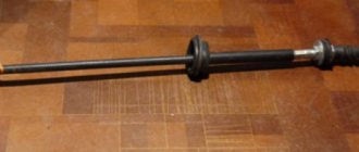
Belt
Often, the solution to a poorly functioning alternator is simply adjusting the belt.
- For the device to work effectively, it is necessary to ensure normal deflection of the belt;
- The deflection size should be 6-10 millimeters with a force of 98 N or 10 kgf;
- To adjust or replace the belt, you need to move the generator slightly to the side, towards the cylinder block;
- By rotating the adjusting bolt, you can adjust the belt tension.
If this measure does not help, you will have to pay attention to the voltage regulator and brushes.
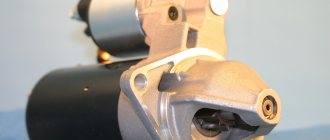
How does a generator work?
In order to determine the generator malfunction, and also to successfully eliminate it, it is important to know the principle of operation of the device. The main parts of a car generator are:
Essentially, the generator converts the rotational motion transmitted from a running motor into electrical energy.
The generator pulley serves to implement the timing drive. When the rotor rotates, a magnetic flux is generated, the strength of which is regulated by a relay controller.
The voltage is transmitted from the commutator rings to the brushes. The rectifier bridge, consisting of diodes, causes the electric current to flow in only one direction.
A relay-regulator or “chocolate” limits the output voltage within 13.6-14.7 V.
The rotation of the rotor shaft occurs in bearings, the smooth operation of which determines the ease of rotation.
Generator repair for VAZ 2110, VAZ 2111, VAZ 2112
Welcome! A generator is an electrical device that supplies current to the car’s on-board network and charges the battery when the engine is running. If it fails, then the first problem that begins with the car is that the battery charge lamp lights up (we’ll talk about this lamp a little later) and the car directly I mean, you can’t drive after this, the whole point is that the ignition system of any car that runs on gasoline consumes electricity and conducts it (High-voltage wires, spark plugs and other units conduct electricity), thereby the engine works, and if suddenly the battery runs out and no current is supplied to the on-board network, the car will simply stall and will not start again until the battery is charged again.
Note! To carry out the generator repair procedure, you will need to stock up on: Be sure to have a multi-meter and, if possible, a test lamp, as well as a screwdriver, various kinds of wrenches (spanners, sockets, etc.), in addition, you will also need a marker and fine-grained sandpaper!
Summary:
When should a generator be repaired?
If it stops supplying current and the voltage going to the battery drops (By the way, the voltage can be checked using a voltmeter, to do this it will be enough to start the car and connect the wires of this device to both terminals, if the device itself shows too low a voltage and while the car is running the volts will drop, then this indicates that the generator is faulty and needs to be replaced), then it must be replaced, in addition to this method, you can also check the generator like this: start the car and let it work for a while, then pull out the choke to about the middle and remove the minus terminal from The battery, if the car stalls, then the generator needs either repair or replacement (This operation cannot be performed on injection cars, and on a carburetor it is also not advisable, because the diode bridge can burn out, so carry out it at your own peril and risk and if everything after all, they threw it off and the car did not stall, immediately install the terminal in its place and tighten the nut that secures it), the last way to understand whether it needs repair or not is the battery charge lamp (by the way, it is indicated by an arrow in the photo below) , so if this lamp suddenly lights up while the engine is running, then again, there is a high probability that the generator is not producing current and needs to be repaired.
Generator - disassembly, checking parts and assembly
To complete the work you will need:
– a power supply with adjustable voltage up to 20 V or a battery charger;
– three or two-jaw puller (see 4.2, clause 12);
– a mandrel from the cup puller set (see 4.2, paragraph 15) for pressing out the front bearing.
1. Remove the generator from the car (see 13.1.3).
2. By squeezing the three spring clips, remove the protective casing of the rectifier unit.
3. Use a Phillips screwdriver to unscrew the two screws securing the voltage regulator.
4. Disconnect the wire block from the voltage regulator terminal and remove the regulator.
8 mm spanner
unscrew the three bolts connecting the terminals of the stator windings to the rectifier block (1), and another bolt securing the rectifier block (2) (remember how the insulating and thrust washers are installed).
6. Carefully bend the wires of the stator winding leads towards the side.
7. Use a Phillips screwdriver to unscrew the screw securing the capacitor.
8. Remove the rectifier unit along with the capacitor. 10 mm socket wrench
Unscrew the two nuts of the contact bolt. We remove the spacer and insulating bushings from the bolt, remove the bolt from the rectifier unit and remove the capacitor tip from the contact bolt.
9. Use a marker to mark the relative positions of the front and rear covers of the generator (to simplify assembly).
8 mm socket wrench
Unscrew the four bolts holding the front and rear covers of the generator together.
11. Use a slotted screwdriver to carefully push the generator covers apart.
12. Disconnect the back cover together with the stator winding from the front cover.
To determine the technical condition of the rear bearing, rock it from side to side and vigorously rotate its outer ring. The bearing should not have significant play, and the ring should rotate freely without jamming or extraneous noise. A faulty bearing must be replaced.
13. Use a marker to place a mark on the stator (to indicate its position relative to the back cover).
14. Remove the stator from the rear cover of the generator.
To determine the technical condition of the front bearing, hold the pulley with your hand, rock it from side to side and rotate the front cover. If the bearing seizes, has significant play, or makes noise when the cover rotates vigorously, it must be replaced.
The manufacturer recommends replacing the front rotor bearing together with the front cover of the generator, since it is rolled into the cover. But, given that the cost of the bearing is significantly lower than the cost of a new front cover and, moreover, the generator assembly, it is advisable to press out and replace the faulty bearing.
15. If necessary, replace the front bearing of the generator with a 24 mm
Unscrew the pulley fastening nut, holding the pulley with sliding pliers.
16. Remove the pulley with the spring (3) and flat washer (2), and the spacer sleeve (1) from the rotor shaft.
17. Screw the pulley mounting nut onto the thread of the rotor shaft (flush with the end). By hitting the nut with a hammer with a rubber striker, we press the rotor out of the front bearing.
18. If it is necessary to replace the front bearing of the generator, install the front cover in a vice (soft metal pads must be put on the jaws of the vice).
19. Having selected suitable mandrels from the cup puller set (see 4.2, paragraph 15), press the bearing out of the seat in the front cover.
20. If it is necessary to replace the rear bearing of the generator, secure the rotor in a vice with soft pads on the jaws. Using a universal puller (see 4.2, paragraph 12), we press the rear bearing from the rotor shaft.
1. Check the stator windings: a) by applying ohmmeter probes to the contact rings of the rotor, check the field winding for a break. The resistance of a serviceable excitation winding should be 5-10 Ohms;
b) by connecting the ohmmeter probes to any slip ring and to the rotor, we check the field winding for a short to ground. If the rotor winding is working properly, the ohmmeter should show an infinitely high resistance.
2. Check the stator windings: a) alternately connecting the ohmmeter probes to the terminals of the stator winding, check the winding for an open circuit. If there is no break, the ohmmeter will show low electrical resistance (about 10 Ohms);
b) by connecting the ohmmeter probes to any terminal of the winding and to the stator, we check the stator winding for the absence of a short to ground. If there is no short circuit, then the ohmmeter should show infinitely high resistance.
3. Check the rectifier unit:
A good semiconductor diode conducts current in only one direction. A diode is faulty if it does not conduct current or conducts current in both directions.
a) connect the probe of the positive terminal of the ohmmeter (in diode testing mode) to the common bus of the auxiliary diodes (1), and the probe of the negative terminal to the terminal of the diode being tested (2). A working diode should not pass current (the resistance tends to infinity);
b) change the tester probes. If the diode is working properly, the ohmmeter should show the presence of resistance (several hundred ohms). Similarly, we check the other two auxiliary diodes;
c) connect the probe of the negative terminal of the ohmmeter to the plate of the rectifier block, into which the diode being tested is pressed, and the probe of the positive terminal to the terminal of the diode. A working diode should not pass current (the resistance tends to infinity);
d) swap tester probes. If the diode is working properly, then the ohmmeter should show a resistance of several hundred ohms).
We check other power diodes in the same way.
4. Check the voltage regulator:
a) inspect the brushes of the voltage regulator, making sure they are mobile. If the brushes are broken or badly worn (protrude no more than 5 mm
), or they get stuck in the brush holder - the voltage regulator needs to be replaced;
b) to check the voltage regulator, we assemble a simple circuit (see below). We connect the negative terminal of the power source to the “ground” of the regulator, and the positive terminal to its terminal. We connect the test lamp to the brushes of the voltage regulator.
When connecting voltage supply wires to the voltage regulator, strictly observe the polarity. Incorrect connection of wires will damage a working voltage regulator.
Using a voltmeter, we monitor the voltage supplied to the voltage regulator;
Scheme for checking the relay regulator:
1 – multimeter (in voltmeter mode); 2 – control lamp; 3 – “ground” of the voltage regulator; 4 – voltage regulator output; 5 – brushes
c) turn on the power supply and supply 13 V to the voltage regulator. The control lamp should light up, indicating that at this voltage in the vehicle’s on-board network, the excitation current will flow to the generator rotor winding;
d) gradually increase the voltage until the control lamp goes out. The voltage at which the control lamp goes out should be 14.5-14.7 V.
e) reduce the supplied voltage until the control lamp lights up again. The voltage at which the control lamp turns on should not be lower than 13.2 V. 5. Checking the capacitor:
You can measure the capacitance of a capacitor only with a special device. You can verify that the capacitor is faulty using an ohmmeter with a measurement limit of at least 1000 kOhm
We connect an ohmmeter to the terminals of the capacitor and observe its readings. If the capacitor is not broken, then when the device leads are connected to it, the ohmmeter will initially show a small resistance, then this resistance will quickly increase until it stabilizes. A similar change in ohmmeter readings should be repeated when the polarity of the device is changed.
A faulty rotor, stator, capacitor or voltage regulator must be replaced. If one or more diodes in the rectifier block are faulty, the complete block should be replaced.
Before pressing the front bearing of the generator into place, it is necessary to check the bearing seat and, if necessary, use a knife or scraper to restore the chamfer where the edges of the hole remain jammed. When pressing the front bearing into the cover, the force must be transferred only to the outer race of the bearing.
1. Having selected suitable mandrels from the cup puller set (see 4.2, paragraph 15), press the new front bearing into the seat in the front cover until it stops.
How to repair a generator on a VAZ 2110-VAZ 2112?
Note! The generator is not very difficult to disassemble, it is difficult to check it, especially if you don’t know how to use a multi-meter, and even if you know how, there may still be errors, it’s just that the multi-meter will not always be able to show accurate data (Everyone has their own error) and therefore We recommend that before proceeding with disassembly work, simply disconnect the cover from the generator and check the brushes (They most often fail) and, if necessary, replace them with new ones (By the way, if only one of the brushes is worn out, then even the generator does not need to be removed from the car, but simply disconnect the cover from it and, armed with a short screwdriver, unscrew the two screws that secure the voltage regulator and then, taking out the regulator, look at the very brushes that are located on it and which, if severely worn, must be replaced)!
How does he work
First, let's figure out how this device functions. His work scheme is as follows:
- The key is inserted into the ignition switch;
- The current goes to the excitation wires;
- The magnetic field created by the armature passes through the stator windings, and voltage appears at its terminals;
- When the armature rotation frequency becomes high enough, the self-excitation mode begins;
- The rectifier unit provided by the car design converts alternating current into direct current;
- The voltage regulator starts working when the crankshaft rotation speed changes, and the time for which the excitation wire is activated is adjusted.
The presented video will allow you to clearly get acquainted with the principle of operation of the generator.