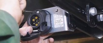
Types of Truck Lighting Sockets
Often, all new tractors are equipped with two lighting connectors - S and N types. Each of them is responsible for a specific function.
More details about them:
- Type N is designed for wiring brake lights and indicators from the truck to the trailer. For example, a DAF tractor unit connects the front fog lights this way.
- Type S is used to transmit power to reversing lights, as well as fog lights. For example, a Renault truck tractor has this type of connection.
Their appearance is often no different, but sometimes they can have different colors, for example:
- White cover – S.
- Black – N.
Despite their similarity, they have specific wiring:
- N is equipped with contacts of the same thickness, only the ground connector has a larger diameter.
- As for S, its mass resembles the shape of a tube.
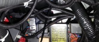
In addition to the above sockets, almost every Schmitz, MaZ, DAF or KAMAZ tractor has a 15-pole lighting system, as well as ABS and EBS. The Ford truck tractor is a little different.
Types of lighting sockets are presented in the following video:
Trailer sockets – Auto parts and auto tricks
Skip to content
Main menu:
- Let's begin...
- < manuals > DIAGRAMS in one click DAF XF-105 2006-2013
- XF 2013-2017
- 95XF
- MAGNUM 2000-2006
- Tricks
- KP
- WORKSHOP Information READING THE DIAGRAMS
- Practice
- Codes 5556, 5038
- SPN 3673
- Supercharging
- EDC EDC
- EBS
- OBD system
- TGS / TGX Wiring diagrams
- Usage
- Electrical circuits
- EDC MS 5 Troubleshooting
- Functional description
- Troubleshooting
- Fault codes
- Fault codes
- Fault codes
- Fault codes
- Fault codes
- Fault codes
- Fault codes
- Fault codes
- TGA AS-Tronic
- Fault codes
- Fault codes
- Fault codes
- Description
- Fault codes
- Fault codes
- Fault codes
- Fault codes
- Airtronic Fault Codes
- Description
- Fault codes
- Fault codes
- Fault codes
- Fault codes
- Fault codes
- Description
- Electrical equipment
- MAN EURO 6
- Tricks
- MX-11/MX-13, EN2/14 MX motors
- PACCAR
- "MIL" for ECS-DC4 and EAS
- Decoding
- ECAS-2
- ABS/ASR-D
- EST42
- EAS
- Abbreviations
- troubleshooting
- EST 52
- ACH-EW
- EBS
- Cabin suspension
- CAN Topology
- ZF EST42
- EBS 2
- Description
- Pneumatics
- BBM
- Electrical circuits
- Electrical circuits
- Diagnostics
- Components LF45 IV, LF55 IV
- ACTROS 950-954 Reg. engine
- Tricks
- MR euro 2-3
- MR "Code"
- Rear module
- Automatic transmission GS II
- Automatic transmission GS II
- TCM TCM
- MCM
- ATEGO codes 950-954
- Wiring diagrams MR OM904
- ABS wiring diagrams
- Wiring diagrams MR MR
- ABS/ASR
- MR Electrical Diagrams
- ADM wiring diagrams
- HYD wiring diagrams
- Wiring diagrams MR
- Wiring diagrams MR
- SPRINTER 909 CR4_T1N-OM646
- CDID3S2-OM651
- EURO TRAKKER Wiring diagrams
- TECTOR
- Electrical circuits
- Electrical circuits
- Eurotronic gearbox
- Repair zone Workshop HPI with EDC S6 Fuel pressure
- AdBlue-OFF
- in winter
- SCR
- Introduction
- Engine
- Description
- Diagnostics
- Description
- EBS System design
- ABS BOSCH
- Diagnostics
- PDE (EDC) MS6 Diagnostics
- Description MS5
- Components
- AGR
- WORKSHOP SAE J1939
- Smoke
- VIN code
- Balance checks. cylinder
- Description of FM4
- FH4 D13 A400
- EBS Description
- Description
- FM (4) Wiring diagram
- Electrical circuits
- Designations
- Electrical circuits
- Electrical circuits
- FH (4) Wiring diagrams
- ECM
- MID 128 D9,D12,D16
- MID 144 codes
- VN/VHD/VAN
- euro 6
- Service
- TRAINING...Wiring
- Premium DXi Chassis - Cab
- Designations
- Electrical circuits
- Electrical circuits
- EURO 4 Wiring diagrams
- Electrical circuits
- R/block, CAN, ADR
- Electrical circuits
- Electrical circuits
- Service. instructions
- AUMAN Electric system
- CARGO Wiring diagram
- Training Fuse Box
- Fault codes S05C / D_S05C-TB
- J and S series
- Electrical circuits
- Electrical circuits
- Components
- SX3255DR
- Electrical diagram
- Canter EURO 3 Wiring diagram
- Common rail engine
- FLC Cummins
- T800
- MB EURO 3/4 scheme
- WORKSHOP Webasto heaters
- Cummis CM2150
- BOSCH MS 6.1
- crankshaft/camshaft
- CUMMINS
- AS-Tronic
- Description
- 5490 Electrical diagram
- ABS
- ABS
- CUMMINS
- 6370 ABS 6 Device
- Rem. VOLVO zone Reading diagrams
- Electrical circuits 203
- Scania Touring Electrics
- Automatic transmission ZF
- Pneumatics
- Suspension ELC suspension
- B12B_B12M
- BH120F
- NL243/283
- Electrical circuits
- 5292_22
- Futura
- ECU CM2150E
- Engine
- SB 220 GS/LT
- XMQ6120C
- E200 MMC
- A092 / A0921
- ETS and MTS
- Komatsu Tech. documentation
- PC200(220) 6 Excel
- CAT Dictionary
- EX300 - 5
- Collection of schemes
- LTM 1100 Fault codes
- LR1600
- Fault codes
- EK-18 Perkins
- Mega collection
- JS145W
- Fault codes Telescope CODE
- Mini loader
- Fault codes
- Fault codes
- Front. episode 3
- Tractor T6 fault codes
- Tractor T9
- Front Loader
- Front. episode 3
- Fault codes
- Electrical circuits
- Wiring diagrams DL
- D.L.
- BW 213 / 214 Wiring diagrams
- Wiring diagrams CVT 6140 - 61195
- Reading the diagrams
- 350D and 400D-II
- 210K EP
- 540H and 548H
- 9120 — 9620
- 335C
- 318E and 320E
- 210LE
- 9560, 9660 Circuit diagrams
- XCG 210LC-8B
- Electrical circuits
- Jaguar 695
- Service info.
- A350 schematics
- Scheme
- SUPER 2500
- BHL
- SAME
- H12T-H20T
- Collection of schemes
- Service manual
- Service. collection
- TMS700E
- LOGLIFT 59
- NH/Case/Steyr
- WORKSHOP Knorr simulator
- ECAS
- Systems
- EBS D system
- Components
- EBS E system
- Thermo King Wiring Diagrams
- Electrical circuits
- System
- TEBS TEBS 4
- VOLVO VOLVO PTT 2.7…
- MAN-Cats II v14.01
- DAF Davie XDc II 5.6.1
- Xentry 06.2020
- VOLVO PTT update
- SDP3/XCom/SOPS
- Autocom Mercedes Actros Diagnostics
- Diagnostics-video
- ABS sensors
- DAVIE DAVIE and fuel
- ABS 6 Diagnostics
- Rem. TEBS E zone
- Components
- Description
- Teplostar 14TS-10
- Fault codes
- Heater calculations
- AIRTRONIC
- 4D-24
- AT 2000
- Description
- Webasto BBW/DBW46
- Thermo 300
- DAF
- CUMMINS Cummins ISB/ISBe Fault Codes
- Fault codes
- Description
- Fault codes
- Diagnostics
- EMR3
- Tier 3 fault codes
- DDEC components
- 4.5L and 6.8L
- MX-13 Fuel
- TELMA Wiring diagrams
- 3000_4000 series
- ESU - 1A Diagnostics
- Description of the ECU
- CM2150
- CP faults
- ABS-T Diagnostics
- Screen components
- StoneRidge - 2400
- Spare parts store (used) MAN
< manuals > > Trailers
Trailer sockets
Trailer socket 7-pin
Pos. contact Function name
- 1 Chassis weight - rear vehicle/trailer weight connection
- 2 Left trailer parking light
- 3 Trailer left turn indicator lights
- 4 Trailer brake light
- 5 Trailer right turn indicator lights
- 6 Trailer parking light, right
- 7 Not connected contact
Trailer socket 15 - pin
Pos. contact Function name
- 1 Trailer left turn signal lights
- 2 Trailer right turn indicator lights
- 3 Trailer fog light
- 4 Chassis weight - rear vehicle/trailer weight connection
- 5 Left trailer parking light
- 6 Trailer parking light, right
- 7 Trailer brake light
- 8 Trailer reversing light
- 9 Power supply after general switch + 24 V trailer
- 10 Not connected contact
- 11 Not connected contact
- 12 Not connected contact
- 13 Not connected contact
- 14 Power supply after general switch + 24 V trailer
- 15 Not connected contact
Trailer socket 7-pin
Pos. contact Function name
- 1 Chassis weight - rear vehicle/trailer weight connection
- 2 Trailer perimeter detection module
- 3 Trailer reversing light
- 4 Power supply after general switch + 24 V trailer
- 5 Trailer ABS indicator light
- 6 Power supply after contact + 24 V trailer
- 7 Trailer fog light
Trailer socket 7-pin "ABS/EBS"
Pos. contact Function name
- 1 Power supply after general switch + 24 V trailer
- 2 Power supply after contact + 24 V trailer
- 3 Chassis weight - connection rear vehicle/trailer weight
- 4 Chassis weight - rear vehicle/trailer weight connection
- 5 Trailer ABS indicator light
- 6 Not connected contact
- 7 Not connected contact
Let's begin... | <manuals> | ENCYCLOPEDIA | Services... | Contacts | Home Site Map
Ways to connect an outlet
There are two methods for this action - standard and universal tga.
It is worth understanding each of them in more detail.
Staff
This method is the most practical. But, it is only suitable if the truck already comes from the factory with the necessary connector for installing a Krone trailer and a MAN semi-trailer.
If there is one, then you just need to select the required plug, which needs to be connected according to the wiring on the Truck Carnehl or Schmitz.
This anti-lock installation method does not require any intervention in the electrical wiring.
Universal
If your car does not have a standard socket, you can install it yourself. The only nuance is the presence of an on-board computer in the car.
If it is missing, then to connect the contacts it is enough to use twisting, special clips, or soldering.
Connection features
Adaptive lighting system
Now let's move on to how to connect the trailer using the towbar socket. Typically, when you purchase a towbar for your vehicle, it comes with a connection kit.
But it happens that you have to buy materials and tools separately. They are used to secure and connect the plug to the socket. Buying a set is not difficult, and the price is quite reasonable. I looked through various online stores in Togliatti, St. Petersburg, Moscow, and other large and small cities. I will say that the pricing policy is approximately the same level everywhere. I was guided by sockets from Bosal, because I think the manufacturer is optimal in terms of price and quality. If you decide to connect everything yourself, you can’t do without:
- mounting plate;
- fasteners;
- wiring kit;
- sockets;
- set of wrenches;
- drills and drill bits (if the car does not have a regular place for a towbar and socket);
- connection terminals;
- heat shrink;
- screwdriver;
- soldering iron;
- electrical tape.
Prepare approximately such a set so that in the middle of the work process you don’t have to run for missing elements.
In the absence of a special kit, try to choose a high-quality bracket, durable fasteners and a multi-core wire with a minimum cross-section of 1.5 mm2. Take strictly copper wires.
But there are two installation methods:
- standard;
- universal.
I’ll tell you about them separately. Photo and video materials will help you.
Standard
It is important to use it if the corresponding connectors are already provided on the towbar and trailer. They are connected as needed
Here it is important to understand what kind of wiring or pinout is used. Simply consult your vehicle's official owner's manual for assistance.
This is described both on the Chevrolet Niva and on the more expensive and interesting Subaru Forester SH, for example.
Everything looks something like this:
Follow the manufacturer's instructions strictly. Otherwise, the entire wiring of the car will be destroyed. I am not kidding. This is a responsible job.
Universal
This method is suitable for modern cars with an ECU. There is no standard way to do this.
The ECU is responsible for controlling the rear lighting. If you tamper with the wiring, the on-board computer will simply start giving errors or turn off all the car's lighting. It's sad when the lights don't work. And dangerous.
Therefore, buy yourself an additional coordination unit. A special device that is connected to the machine's electrical network. It sends the necessary signals to the rear optics, since the ECU is not capable of recognizing the trailer’s lighting equipment.
Then we follow the instructions of the standard method, connecting the wires of the trailer plug and the towbar socket to each other. Don't forget to carefully insulate the wires.
As you can see, the most difficult thing about connecting yourself is knowing the trailer connection diagram and the socket pinout. Make sure the trailer plug and socket are aligned. Or buy adapters.
Watch this video on YouTube
Thank you all for your attention! I hope you'll subscribe, tell your friends about us, and leave some interesting comments!
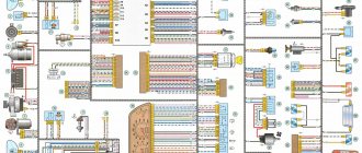
Pin layout in ABS and EBS sockets
No special knowledge is required to connect this type. To successfully implement the plan, it is necessary to pinout the semi-trailer connector.
Pin layout in ABS and EBS sockets.
Pin connectors ABS and EBS:
- The constant “+” at number 30 is responsible for the functionality of the ABS electric valves.
- When the ignition is turned on, “+” under number 15 takes power from the corresponding relay, which is located on the ABS electronic unit.
- Weight for output – 2.
- Weight 1.
- ABS system malfunction warning light.
- Buses CANH and CANL (only when connected to EBS).
The detailed pinout of the semi-trailer socket for each type of transport is below.
For tractor and trailer
Pin for installing ABS and EBS has the following wire colors:
- Dark red.
- Black, less often – gray.
- Bright yellow.
- Brown.
- Pure white.
- White with a light green stripe (in the case of EBS).
- White with brown stripe (EBS only).
Detailed information is visible in the video:
For semi-trailer
In case of connecting the ABS connector, the semi-trailer cable pinout is as follows:
- Dark red color.
- White and red.
- Brown with a blue stripe.
- Dark brown.
- Yellow with a blue stripe.
For VOLVO truck
Wiring of contacts.
When connecting ABS and EBS connectors on these car brands, there is a pinout of the following color:
- Red with a cross section of 6 mm²/4 mm².
- Light grey.
- Cloudy white.
- White, the cross-section of which is 6 mm²/4 mm².
- Brown.
- Pink.
- Purple.
For IVECO truck
When connecting to tractors of this brand, the semi-trailer transfer pinout has the following color:
- Red with a cross section of 4 mm².
- Green with a cross section of 1 mm².
- Brown with a cross section of 1 mm².
- Brown with a cross section of 4 mm².
- Purple with a section.
- White-brown with a cross-section of 2.5 mm².
- White-green with a cross-section of 2.5 mm².
Connecting the socket is clearly shown in the video:
Types of connectors and connection diagrams
There are several types of automotive electromechanical plug devices, in particular:
Some American cars use four-pin sockets.
Seven-pin connectors can be of European or American design. In Russia, European pinouts are most often used. This scheme for connecting a trailer socket is not complicated, so most car enthusiasts do it themselves.
The wires are connected to the contacts using screws. The towbar connector pins are numbered clockwise, while the trailer plug is numbered counterclockwise. Both parts of the connector have different types of contacts - sockets and pins. This is done to ensure safety when connecting the socket to the trailer at night.
15-pin socket pinout
This type can be found on almost all European, Asian and Russian cars.
It is worth noting that the pinout of the 15-pin socket on semi-trailers, regardless of the make of the vehicle, is the same for all, the only difference can be in the color.
For tractor
13-pin socket pinout.
You can only see this pinout on the diagram, which you need to find on the Internet yourself.
For trailer and semi-trailer
This type is the accepted standard for almost all tractor models.
It is worth noting that the fifteen-pin plug does not allow connecting a Tonar or Krona trailer via a 13-pin one.
American connecting chips
Many American standards differ from European ones, and trailer hitch socket pinouts are no exception. Here are two types for your reference: 7 and 4 pin connectors.
The 7-pin socket, used in the HOPKINS model range, as well as in other cars (Fig. 8), differs from the European standard practically only in design, which allows, if necessary, replacement with a European analogue.
American 7-pin towbar socket
Designations:
- Connecting side lights.
- +12 V.
- Starboard turning lights.
- Brake light control.
- Weight.
- Turning lights on the left side.
- Reverse signal.
Now let's consider a more complex option - a 4-pin connector (see Fig. 9). If you try to replace it with a European 7-pin socket, problems will arise.
4 pin connector
Designations:
- Weight.
- Control of side lights.
- Left side turn signal and brake light control.
- Starboard turn signal and brake light control.
As you can see, the difficulty is due to the fact that the turn signals and brake lights are controlled along the same line. There are two ways to solve the problem:
- Not entirely correct, but the easiest way: connect directly to the stops and turn signals. Note that in some cars the wiring may not withstand the additional load, so it is better to solve the problem in another way.
- This option is somewhat more complicated, but more correct: you need to completely extend the wiring under the European connector. For example, in a Chevrolet Tahoe, to do this you need to remove the instrument panel, find wires with separate signals for the turn signals and brake lights, connect to them by stretching the electrical wires from the towbar socket through the entire interior of the car. You can make the task a little easier if you take the signal for the brake lights from the rear fender; it is displayed there on almost all cars. In this case, you only need to pull two wires.
Car trailer socket pinout - towbar connection diagram
Connecting a towbar (truck trailer) is a simple procedure. Connecting a trailer to a car is really easy, but connecting the electrical to the trailer can already be a bit of a hassle. In such cases, you will need a wiring diagram for the towbar socket. And there are several types of connectors:
- seven-pin (7 pin) European-type connectors;
- American-type seven-pin (7 pin) connectors;
- thirteen-pin connectors (13 pin);
- special connectors.
The most common types of sockets have 7 and 13 contacts. In Russia, 7-pin devices are usually used, and 13-pin sockets can be seen on many cars from Europe and the USA. The difference lies in the use of additional contacts necessary to activate fog lights and other electrical components of caravans that are popular abroad.
Rules accepted throughout the world provide for the installation of left/right turn signals and stop signals on trailers for passenger cars.
The connection diagram for a passenger car trailer socket depends not only on the number of contacts, but also on the standard of the country, so a trailer with European wiring cannot be connected to a socket with Russian wiring without modification. If you install it without modification, then the right dimensions of the BTS will not light up.
Direct connection diagrams
If the towbar and trailer of a passenger car (and truck) are equipped with the appropriate connectors, then the electrical connection diagram will not be needed at all, since you just need to insert the socket into the socket.
Pinout of 7-pin trailer socket Euro and RF
- Left side turn signal.
- Reversing lamp.
- Earth.
- Right side turn signal.
- License plate light and right side marker light.
- Brake light bulbs.
- Right side marker light.
US 7 pin trailer socket pinout
A special feature of the connector is the presence of a reverse contact and the absence of separation between the right and left rows of side lights. In some models of American cars, there is no separation between side lights and brake lights (they run on one wire).
Pinout diagram for 13-pin socket
- Left side turn signal.
- Rear fog lamp.
- Ground for terminals 1 to 8.
- Right side turn signal.
- Left side of dimensions and number plate illumination.
- Brake light lamp.
- The right side of the dimensions and number plate illumination.
- Reversing lamp.
- Constant voltage 12 volts 35 amps.
- The voltage is 12 volts 35 amps, supplied after the ignition is turned on.
- Ground for terminal.
- Signal wire.
- Ground for terminal 9.
Useful: DIP chip packages
When the car is not equipped with a modern electronic control unit. Thanks to this, electrical wires can be directly connected to existing electrical circuits.
That is, the wires that come from the connector are connected to those connected to the rear lighting equipment.
Electronic matching unit
If we are talking about a modern car with complex electronic components, the first option for connecting a trailer will not be the best choice. The control unit tests the rear optics.
When it determines that it is consuming more current, it will display an error message. In such cases, the so-called “matching block” is used.
It is also used in the case of transmitting control signals via a multiplex bus.
The wiring is connected to signal circuits, only in this case the signals to the lighting equipment of the towed device come not from the car, but from the matching unit, and its presence is not perceived by the electronics. Additionally, the unit must be connected to a used car.
Materials for connecting the tow bar
We go to a car store or car market and buy the materials necessary for installation and connection:
- socket housing for tow bar with cover and rubber O-ring. We pay attention to the normal fit of all parts of the housing, the absence of play or the pressed brass contacts dangling in the sockets, we check the threads and the condition of the fastening screws on the terminals.
- high-quality single-core wire used in car electrical wiring, wire cross-section not less than 1.5 mm2; connecting blocks, it is better to use a model with fuse sockets.
- polypropylene or metal corrugated hose for insulating wiring harnesses - 2-3 meters, and a couple of dozen plastic mounting clamps for fixing wiring harnesses.
- silicone gasket, choose color and manufacturer to suit your taste.
Features of the socket connection
To connect the towbar to the vehicle's electrical wiring, we recommend using stranded copper wire. The ideal option is a wire in which each core has a cross-section of at least 1.5 square meters. mm. The wire must have a double layer of insulation.
After connecting the trailer according to our diagram and checking the functionality of its lighting equipment, it is advisable to take care of protecting the internal elements of the outlet from moisture. It would be a good idea to use graphite lubricant, which will also prevent oxidation of the contacts.
7— 3,71
CLICK HERE AND OPEN
Standard and universal towbar socket connection diagrams
When operating a vehicle with a trailer, any connection diagram for the towbar socket on a VAZ 2106 can be used
During the process of installing the towbar, it is important that all electrical equipment operates in normal mode. And it should not happen that when you press the brake pedal the turn signals would flash
In the towbar socket, all contacts are located in a certain sequence, so you can subsequently use any trailer.
How to install a tow bar on a VAZ 2106
You need to install the towbar (towbar) according to the following algorithm:
- It is most convenient to carry out all work from below the car. Therefore, you will have to use an inspection hole, a lift or an overpass.
- Disconnect the negative terminal from the battery.
- Remove the trunk trim and get rid of foreign objects.
- Mark the position of the tow bar relative to the body. Mark the location of the mounting holes.
- Make holes for fasteners. Before installing the towbar, be sure to treat it with anti-corrosion compounds, otherwise the metal will begin to rust.
- Bolts, washers and nuts are used as fastening elements. Bait them and tighten them.
- Drill two holes. One is in the lower part of the spar, the second is in the trunk. Install reinforcing pads to significantly strengthen the fasteners and remove excessive load from the car body elements.
- At the last stage, the electrical wiring is installed. It can be done in one of two ways.
Standard socket connection method
The trailer has a plug that has 7 or 13 pins. It will not always be useful, so motorists use a universal method of connecting the towbar socket. On most domestic cars of the “classic” VAZ 2101-2107 family, the installation of coordination and control units is not provided. Therefore, the socket is installed for a specific trailer. To do this, you only need to know the pinout of the plug. The socket is connected by a wiring harness to the rear light of the car.
Before connecting the towbar socket, carefully study the vehicle wiring. The best installation method is to connect the socket to the rear light using plugs. Enough for 7 plugs:
- Weight (minus battery).
- Left turn signal.
- Right turn signal.
- Stop signal.
- Parking lights.
And a couple of spare ones wouldn't hurt. In the event of a breakdown, you can quickly transfer the wires from one contact to another. Carefully study the rear light diagram so as not to make mistakes during installation. And you will have to install other fuses. Standard ones installed on a car have a current reserve of about 25% - this is the normal value used in calculating electrical circuits.
As the load increases, the maximum permissible current becomes higher, so you need to replace several fuses, maintaining a margin of about 25%.
Universal connection method
For owners of modern cars, connecting the socket will be easier. And all this is due to the fact that the wiring itself is much more complex. You will have to install a special matching unit. With its help, all optics of the tow hitch are diagnosed. And if the current consumption increases (during a short circuit), the driver will be warned. A notification will also occur if one of the lamps fails (the current consumption decreases). For this reason, experienced auto electricians advise using a matching device.
Installing a towbar socket on VAZ cars using a universal method:
- Install the matching device and connect it to the car wiring. Connect the connectors according to the diagram. To activate the matching device, you need to turn it on by applying power. The optics on the trailer will start working, depending on what signal is being received.
- In rare cases, the connectors on the matching unit and the trailer do not match. There are many manufacturers of electrics and trailers, which is why such “disagreements” happen. But if you have a pinout diagram for the trailer plug and the car’s electrics, you can solve this problem quite quickly.
The functioning of optics on a trailer depends on the quality of installation. Carefully insulate exposed wire sections to prevent short circuits.
How to connect a towbar socket
When faced with an outlet connection problem, an owner can consider one of two methods:
- standard;
- universal.
The first method can only be considered if the towbar, like a car trailer, has the appropriate connectors that allow the connection to be made.
Then the owner can do the work without even having a trailer wiring diagram in hand. Indeed, in this case, all actions will be reduced to combining the socket with the socket. Often, information about the pinout of the towbar socket can be obtained from the vehicle’s operating instructions. This is exactly what should be done, since the owner will not have to change the electrical system of his car in any way.
However, what most often happens is that owners have to resort to a universal method. However, to get a more complete picture of the features, both of these options will be considered below.