What is a datasheet and why is it needed?
Datasheet is a technical specification that provides complete information about a radio component.
All technical information, basic connection diagram, parameters and types of housings are indicated in this document. Datasheets come in different languages, mostly in English. There are also translated versions.
Documentation for the NE555 chip. The body and appearance of the part are drawn.
The microcircuit, its parameters and operating conditions are described in detail here.
Such documentation is available for any detail. This is very convenient and informative, especially when searching for analogues. And with the help of the Internet, searching for analogue parts or diagrams has become even easier.
The datasheet also allows you to identify an unknown part or microcircuit. Just write its name in a search engine, add the word datasheet, and all the documentation will be in the search results.
Car electrical circuit symbols
Reading electrical circuits with a transistor
Symbols of electrical circuits of cars shown in table. "Schematic symbols according to EN 60617" are a selection of standardized symbols suitable for automotive electrical applications. But, with rare exceptions, they comply with International Electrotechnical Commission (IEC) standards.
Table of schematic symbols for electrical circuits of automobiles according to EN 60617
The European standard "Graphic symbols for circuits" EN 60617 corresponds to the international standard IEC 617. It is published in three official versions (English, French and German). The standard contains symbol elements, index symbols and, most importantly, electrical circuit symbols for the following areas:
- General Applications Part 2;
- Conductors and connecting devices part 3;
- Passive components part 4;
- Semiconductors and vacuum tubes part 5;
- Electricity production and conversion part 6;
- Switching and control equipment and protective devices part 7;
- Measuring instruments, lamps and signaling devices part 8;
- Telecommunications transmission, switching and peripheral equipment part 9;
- Telecommunications, transmission equipment part 10;
- Architectural and topographical installation diagrams part 11;
- Binary elements part 12;
- Analog elements part 13.
Requirements for electrical circuit symbols
Electrical circuit symbols are the smallest elements for a simplified graphical representation of an electrical device or part of it.
Electrical circuit symbols show the principle of operation of the device and functional connections of a technical nature. Electrical diagram symbols do not take into account the shape and size of the device, or the position of the connections on the device. An isolated representation on a circuit diagram is only possible in the abstract.
Electrical circuit symbols must have the following properties: they must be easy to remember, easily understandable, simple to display graphically, and fit logically into a classification group.
Electrical circuit symbols consist of elements and index symbols. Some examples of index symbols include letters, numbers, symbols, mathematical signs and symbols, unit symbols, and characteristic curves.
If the electrical diagram becomes too detailed due to the representation of the internal circuitry of a device (Figure a, "Wiring Diagram and Schematic Symbol of a Generator with Regulator"), or if not all of the circuit parts are needed to identify the function of the device, then the electrical diagram for that particular device can be replaced one symbol (without internal circuit) (Fig. b, “Electrical diagram and schematic symbol of a generator with a regulator”).
In the case of integrated circuits that provide a high degree of space saving (synonymous with a high level of integration of functions in the component), a simplified representation of the circuit is preferable.
Illustration of electrical circuit symbols
Circuit symbols are displayed without the effect of physical quantity, i.e.
in a de-energized and mechanically non-activated state. The operating state of a schematic symbol that differs from this standard image (base state) is indicated by a double arrow (Fig. “Operating state of a schematic symbol other than the base state”). Circuit symbols and connecting lines (electrical wires and mechanical connections) have the same line width.
To avoid unnecessary bends and intersections of connecting lines,
You can rotate circuit symbols in 90° increments or display them as a mirror image, provided that their meaning does not change. The direction of continuous lines can be chosen arbitrarily. Exceptions are circuit symbols for resistors (where connection symbols are only allowed on narrow sides) and connections for electromechanical actuators (where connection symbols are only allowed on wide sides, Fig. Terminations).
Connections can be shown with or without a dot. If there is no dot at the intersection, there is no electrical connection. Connection points on devices are mostly not displayed specifically. Connection points, plugs, sockets or threaded connections are identified by diagram symbols only at the points required for installation and removal. Other connection points are usually indicated by dots.
Contact elements with a common drive are designated on the wiring diagram in such a way that, when activated, they follow the direction of movement established by the mechanical connection (- - -) (Fig. “Mechanical connections on a multi-position switch”).
Basic aspects of correctly reading an equipment electrical diagram
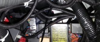
So, how to read car diagrams and what you need to know about deciphering them? As you already understand, without knowledge of decoding you will not be able to repair wiring and equipment if necessary. A detailed diagram for a specific car model should be noted in the service manual for the car. Looking at it, you can see dozens of various symbols of electrical equipment that are connected by lines. Each of these lines is painted a certain color - this is the color of the wires in the wiring system (video filmed by the MR.BORODA channel).
More modern cars use complex circuitry because these vehicles are equipped with more equipment and devices. In such electrical circuits, conductors may be indicated as segments or with breaks.
What aspects should be taken into account to decipher the electrical circuit of the machine:
- As we have already reported, all electrical circuits are marked with a color corresponding to their actual state. This greatly simplifies the process of repairing and replacing wiring. The color of the conductors itself can be single or double, this indicates whether it is the main cable or an additional one. If additional conductors are meant, then on the electrical circuit itself they are usually marked with hatched segments, which are either longitudinal or transverse.
- If in your car several electrical circuits are located on one harness, and they are marked similarly, then such circuits are characterized by galvanic resistance. That is, these cables are simply connected to each other.
- If the chain fits into the harness, it will be marked with a slight deviation in the specific direction it is facing.
- Typically, on any electrical circuit there are several wires of the same color, usually black. In this case we are talking about electrical circuits connected to ground, that is, the car body. Such contacts are called mass.
- If we talk directly about the relay, then in this case the contacts are indicated in a state when no energy is transmitted through the winding of the device. If the operating state of the device is standard, then these elements may differ from each other, since they can be open and closed.
- In addition, by looking at the electrical diagram, you will see that additional symbols may be marked on the circuits themselves. Namely, we are talking about connecting an electrical circuit to an energy consumer. Such a designation will enable the consumer to find out exactly where the circuit is connected, without exactly tracing its routing.
- If you notice that specific numbers are indicated on devices or equipment, then these numbers must correspond in any case. For example, if there is a circle around the number, this indicates that this is the point where the circuit connects to the negative terminal. If you are interested in combinations of letters and numbers, then this is how plug connections are marked.
Photo gallery “Electrical circuit designations”
Basic Concepts
How to learn to feel the dimensions of a car? exercises and tips for a beginner
To understand on what principle a particular device works, a knowledgeable person can simply look at its electrical diagram
At the same time, it is quite important to take into account several basic nuances that will help even a beginner read such drawings in detail.
Of course, no device can function properly without current flowing through its internal conductors. These paths are indicated by thin lines, the color of which is chosen to match the actual color of the wires.
If the electrical circuit includes a sufficiently large number of elements, the route on it is displayed in the form of breaks and segments, and the places of their connection or connection must be indicated.
In addition, the numbers that are indicated on the nodes must also fully correspond to the real numbers, since reading electrical diagrams (designations) otherwise will be pointless. The numbers indicated in the circles determine the locations of the negative connections with the wires, while the designation of the current-carrying paths makes it easier to find elements located on different circuits. The combinations of letters and numbers fully correspond to detachable connections, and there are quite a large number of specialized tables with the help of which you can quite simply identify the elements of any electrical circuit. Such tables are quite easy to find not only on the Internet, but also in various manuals for specialists. In general, figuring out how to read electrical circuit diagrams correctly is not that difficult. The main thing in this is to understand the functionality of the various elements, as well as to be able to correctly follow the numbers.
To understand how to correctly read automotive electrical circuits, you need not only to have a detailed understanding of the symbols of various components, but also to have a good understanding of how they are formed into blocks. In order for you to understand the peculiarities of the interaction between several elements of an electronic device, it is worth learning how to determine how the signal passes and is converted. Next, we'll look at how to read electrical diagrams. For beginners, the instructions are as follows:
Initially, you need to familiarize yourself with the power circuit allocation diagram. In the vast majority of cases, the places where the supply voltage is supplied to the device cascades are located closer to the top of the circuit. Power is directly supplied to the load, after which it passes to the anode of the vacuum tube or directly to the collector circuit of the transistor. You should determine the location where the electrode joins the load terminal, since at this point the amplified signal is completely removed from the cascade. Install input circuits on each stage. You should select the main control element, and then study in detail the auxiliary ones that are adjacent to it. Look for capacitors located near the input of the cascade, as well as at its output. These elements are extremely important in the process of amplifying alternating voltage. Capacitors are not designed to carry direct current through them, as a result of which the value of the input resistance of the next block will not be able to bring the cascade out of a stable state for direct current. Start studying those stages that are used to amplify a specific DC signal. All kinds of voltage-forming elements are combined with each other without capacitors. In the vast majority of cases, such cascades operate in analog mode. The exact sequence of stages is determined in order to establish the direction of signal flow
In this case, special attention will need to be paid to detectors, as well as all kinds of frequency converters. You should also determine which stages are connected in parallel and which in series
When using parallel cascade combining, several signals will be processed completely independently of each other. In addition to understanding how to read electrical circuit diagrams, you should also understand the wiring diagrams that come with them, which are commonly called wiring diagrams. The layout features of the various components of an electronic device will help you understand which blocks are the main ones in a given system. Among other things, a wiring diagram makes it easier to identify the central component of the system, as well as understand how it interacts with auxiliary systems, since it is difficult to read automotive electrical diagrams without these values.
Symbols on car electrical circuits
The symbols of electrical circuits are not anything complicated. To understand them, you need to have a minimal understanding of the action of electric current.
As is known, current is the ordered movement of charged particles along conductors of electric current. The role of conductors is played by multi-colored wires, which are indicated in the diagram as straight lines. The color of the lines must necessarily match the color of the wires in reality. This is what helps the driver understand thick wiring harnesses and not get confused.
Various contact connections are indicated using special numbers, which are found both on the diagram and at the connection points. As a rule, relays that have many contact pins are required to have such numbers. The elements of the electrical circuit in the diagram are signed using numbers. At the bottom of the diagram or in the form of a separate table, a special decoding of these numbers is displayed, which displays the name of the circuit element.
Let's summarize. Reading electrical diagrams is a fairly easy task. The main thing is to correctly interact with the symbols and be able to understand the symptoms of a malfunction in order to promptly and correctly determine the type and location of the malfunction on the diagram.
Electrical circuits of cars - we analyze the basic principles of reading + video
Today, with such rapid advancement in technology, it is very important to know how to read car wiring diagrams. And don’t think that only owners of modern foreign cars, which are full of automation, need this
Even if you have an old Lada, it will also be useful to familiarize yourself with this information, since the design of any car requires the presence of auto electricians.
What are electrical circuits?
An electrical circuit is an ordinary graphic image that shows pictograms of different elements arranged in a certain order in a circuit and connected to each other in series or parallel. Moreover, such drawings do not display the actual location of these elements, but only indicate their relationship with each other. Thus, a person who understands them can determine at a glance the operating principle of an electrical appliance.
Diagrams always depict three groups of elements: power sources that produce current, devices responsible for energy conversion, and nodes that transmit current, their roles being played by different conductors. Galvanic cells with very low internal resistance can act as a power source. And electric motors are often responsible for energy conversion. All objects that make up the diagrams have their own symbols.
Why understand electrical circuits?
Being able to read such diagrams is quite important for anyone who owns a car, because it will help save a lot of money on the services of a specialist. Of course, fixing any serious breakdowns on your own without the participation of professionals is difficult, and even fraught, because the current does not tolerate mistakes
However, if we are talking about some basic malfunction or you need to connect the battery, ECU, headlights, side lights, etc., then doing it yourself is quite possible.
In addition, we often want to add additional electronic devices into the circuit, such as an alarm system, a radio, or a car air conditioner, which greatly facilitate the driving process and fill our lives with comfort. And here you cannot do without the ability to understand electrical circuits, because they are often included with all of the listed devices. This is also relevant for owners of cars with a trailer, as sometimes problems arise with its connection. And then you will need a wiring diagram for a passenger car trailer and, naturally, the skills to understand it.
How to read car electrical diagrams - basic symbols
In order to understand the principle of operation of a device, a knowledgeable person will only need to look at the electrical diagram. Let's look at the main nuances that will help even a beginner understand the circuits. It is clear that not a single device will operate without current, which is supplied through internal conductors. These routes are indicated by thin lines, and their color should match the actual color of the wires.
If the electrical circuit consists of a large number of elements, then the route on it is depicted with segments and breaks, and the places of their connections or connections must be indicated.
The numbers indicated on the nodes must correspond to real numbers. The numbers in the circles show the connections of the wires with a “minus”, and the designation of current-carrying paths makes it easier to find elements located on various circuits. Combinations of numbers and letters correspond to detachable connections. There are special tables that make it very easy to identify elements of electrical circuits. They are very easy to find both on the Internet and in manuals for specialists. In general, car electrical diagrams are quite easy to read; the main thing is to understand the functionality of their elements and follow the numbers.
What do they contain?
A specialized resistance that changes the current of the electric motor of the stove, and, accordingly, the blowing speed.
These routes are indicated by thin lines, and their color should match the actual color of the wires.
Usually built into its mechanism. Input circuits Often, for those people who roughly understand how to read the electrical circuits of a car, the input circuits of the cascade do not require any explanation.
Also, the need to understand the operation of a particular circuit for a car may arise for those car owners who want to make adjustments to the operation of the system. Elements connected to the same voltage in a circuit are called a branch. In this case, special attention will need to be paid to detectors, as well as all kinds of frequency converters. Contactless sensors are more reliable, but are picky about the voltage of the on-board network.
They find in the directory what it corresponds to and find out all the possible information about the element. An electrical circuit is a specialized graphic image that shows pictograms of various elements that are in a certain order in a circuit, as well as connected to each other in parallel or in series.
However, if we are talking about some basic malfunction or you need to connect the ECU, headlights, side lights, etc., then doing it yourself is quite possible. In this case, it is also important to understand how to learn to read electrical diagrams, because in the vast majority of cases they are necessarily attached to almost every device.
For example, today many domestic drivers do their own vehicle tuning in various ways. All kinds of blocks of the same type or components of the circuit will need to be depicted by copying the presented elements, making the necessary additions and edits later. In the worst case scenario, the speedometer readings will lie, or the speedometer will not show the car’s speed. In addition, you need to understand the operation of the circuit even if you decide to install an anti-theft installation yourself. Naturally, if more complex problems occur in the operation of the network and equipment, then it is unlikely that you will be able to identify them yourself without experience.
Cigarette lighter led into the salon. Determine the unit of measurement in which the electrical circuit will be drawn, as well as the required image scale. It is worth noting the fact that any such drawing does not demonstrate the real location of certain elements, but is used only to indicate their connection with each other. Auto electrics. Legend
How are diagrams formatted in a diploma?
Like all graphic materials, the diagrams in the diploma are called drawings, therefore in the text of the work they are referenced in a standard format:
This is how they refer to the diagram located directly in the work. When an illustration is included in the “Appendices” section, the letter designation assigned to it is indicated. If it is not the only one in a particular tab, then its serial number is specified:
Illustrative materials are placed immediately after the first mention in the text or, if there is no space on the page, on the next sheet.
There are different types of diagrams:
- histogram - classic line or column chart
- circular (sector)
- radial (mesh)
- Venna
- area chart
Any of them is easy to do in Word. To do this, in the toolbar in the left corner:
- Click on “Insert”:
- Go to "Charts".
- Select the appropriate type.
- Enter the relevant data. The program will automatically generate the required graphic illustration.
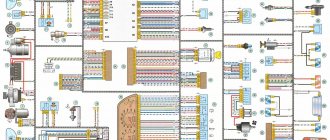
Wiring diagram of a modern car
» Articles » Wiring diagram of a modern car
Failure of the electronic components of a modern car can lead to its complete immobilization. It’s good if this happened near your home or work, but if this happens on the highway or in nature, such a breakdown can cost you extremely dearly: both in terms of money, and in terms of lost time and even (I hope it doesn’t come to that) health !
Why is it useful to understand auto electrics?
Even if you are not technically minded or your income allows you not to think about such mundane details, replacing a regular blown fuse on a long journey will make your life much easier.
I'm not even talking about those cases when servicemen, not wanting to understand the problem of your car, urge you to change all the sensors in a row, spending significant amounts of money on this “carousel” (which, by the way, sometimes does not guarantee a positive result).
Therefore, I suggest that you do not give up ahead of time and try to independently diagnose the breakdown of your car, and for this it would be nice to have electrical diagrams on hand, and most importantly, be able to read and understand them.
Electrical circuits? - even a schoolboy can figure it out!
When I first encountered a schematic electrical diagram of a car, I realized that the principles of its construction and the designation of elements on it are standardized, and those elements that are present in all cars are designated the same way, regardless of the car manufacturer. It is enough to figure out once how to read such electrical diagrams, and you can easily understand what is shown on it, even if this is the first time you have seen a specific diagram from a specific car and have never even climbed under the hood of it.
Graphic designations of circuit elements may differ slightly; in addition, there are black and white and color versions. But the letter designation is the same everywhere. In addition to schematic electrical diagrams, it is useful to have diagrams that indicate the physical location (in space) on the body of various harnesses, connectors and grounding points - this will help you quickly find them. So, let's take a look at examples of such circuits, and then proceed to describe their elements.
An example of a car electrical circuit diagram
The circuit diagram does not indicate the physical relative positions of the elements, but only shows how these elements are connected to each other. It is important to understand that if two elements on such a diagram are shown next to each other, on the body itself they can be in completely different places.
Schematic arrangement of electrical components on the body
Such a diagram carries another type of information: the routing of the cable braids and the approximate location of the connectors on the body.
Three-dimensional accurate diagram of the location of electrical components of the car
There are also diagrams that show exactly how and where the cable routes go in the car body, as well as grounding points.
Standard elements of a car circuit diagram
Let us finally begin to examine the elements of the diagram and learn how to read it.
Standard power circuits and connection of elements
Power circuits - circuit elements that transmit current, are depicted by lines: at the top of the diagram there are circuits with a positive potential (“plus” of the battery), and at the bottom - with a zero potential, i.e. ground (or battery negative).
Circuit 30 - comes from the positive terminal of the battery, 15 - from the battery through the ignition switch - “Ignition 1” Circuit number 31 - grounding
Some wires also have a digital designation at the point of connection to the device; this digital designation allows you to determine where it comes from without tracing the circuit. These designations are combined in the DIN 72552 standard (frequently used values):
For convenience, connections between elements on color diagrams are depicted in different colors corresponding to the colors of the wires, and on some diagrams the wire cross-section is also indicated. On black and white diagrams, the colors of the connections are indicated by letters:
Sometimes you can find an empty circle in a node - this means that this connection depends on the configuration of the car, and the lines are usually signed.
Designation of connectors on the electrical diagram - connectors
Pin No. 2 of connector C301 is connected to pin No. 9 of connector C104, which, in turn, goes to pin No. 3 of connector C107
Wires in car wiring are connected in several ways, and one of them is connectors. The connectors are designated by the letter “C” and a serial number. In the figure on the left you see a schematic representation of the connections of sections of wire through connectors. In general, it is more correct to say not “pin No. 2”, but “terminal No. 2”; if you come across such a concept in the diagram, then now you will know that this is the serial number of the connection (contact) in the connector.
Well, in this figure you can see how the contacts in the connectors are numbered and how to count them correctly in order to find out which pin is which. Contacts are numbered from the “mother” side from the upper corner from left to right line by line. From the “dad’s” side, accordingly, it is mirrored.
Source: https://avtoliders.ru/stati/elektroshema-sovremennogo-avtomobilya.html
How to read car electrical diagrams - basic symbols
So, let's consider the main points that will allow you to correctly read the electrical circuit of the equipment of any vehicle. After all, as stated above, without this knowledge it is simply impossible to repair devices yourself. Of course, no device can function without voltage supplied to the device through internal conductors.
The electrical diagram of the vehicle with the designation of all elements must be in the service book for the vehicle. Looking at it, you will see many different symbols of instruments and devices connected to each other by lines. It should be noted that each of these lines can have its own specific color, which in fact should correspond to the actual color of the wires of the electrical circuit (the author of the video is Avtoelectrica HF).
If the car is equipped with multiple electrical appliances and devices, then a large number of components will be marked on the diagram. Accordingly, the wiring itself may appear with breaks and segments. This may be confusing at first, but there is nothing difficult about it; it is quite possible to figure it out on your own.
Any scheme consists of the following elements:
- Power supply device. In this case, this function is performed by the vehicle’s battery or generator.
- Conductors, that is. These components allow current to be transmitted across the network.
- Control equipment. Such devices are necessary for closing the electrical wiring or opening it if necessary. It should be noted that devices of this type may or may not be present on the electrical circuit.
- Direct voltage consumers. This item includes all electrical equipment that consumes energy by converting current into another type of energy. For example, if we are talking about a cigarette lighter, then this element converts voltage into thermal energy.
If there is a need to repair a vehicle with your own hands, it is necessary to take into account the basic principles when deciphering the diagram:
- Any conductors, as mentioned above, are marked with a certain color on the diagram. As for the color itself, the wire can have one color or two, that is, it can be either primary or additional. If we are talking about additional components, then strokes must be applied to them - they can be transverse or longitudinal.
- If several wires are installed on one harness and are marked the same, then they have a galvanic connection. In other words, these conductors are simply connected to each other.
- In any diagram, if a conductor enters a bundle, it should slope slightly towards where it is located.
- In practice, that is, on most diagrams, conductors are marked in black, which are connected directly to the mass of the vehicle, that is, to its body.
- As for relays, their contacts are marked in the state when no voltage passes through the device winding. In the standard state, these components are different because they can be either closed or open.
- You may also notice that conductors may have certain markings on them, particularly where the conductor connects to the equipment. Thanks to this designation, the driver can immediately understand where this conductor goes without having to trace the circuit as a whole.
Contactless ignition of classic VAZs
If certain numbers are indicated on certain mechanisms, then they must correspond to the numbers. If this or that number is marked in a circle, then this indicates that you have a conductor connection with a minus. As for the number and letter combinations, they correspond to detachable connections.
The service book may include a table that will allow you to easily decipher certain network elements specific to a particular vehicle model. In general, if you have a need to decipher a diagram, then the most important thing is to be diligent in order to understand what this or that designation means. Having understood the principle of decoding itself, you can easily determine the purpose of all elements.
What are car wiring diagrams?
What devices and elements does the vehicle's electrical wiring and electrical equipment system include? A schematic electrical diagram is a visual representation where all the icons of the components used are indicated without exception. All devices are located in a specific order on the diagram, and they can be connected to each other in either a serial or parallel manner. It must be taken into account that the electrical diagram of a car or truck itself does not actually show the actual location of the equipment. It only shows how all consumers and energy sources are connected.
Regardless of the machine, the circuit includes the following components:
- power system equipment used to generate voltage;
- devices used to convert energy;
- In addition, the network also includes components used to transmit current, that is, conductors.
How to Read Electrical Diagrams - Graphics, Letters and Numbers
Designation of fuses on electrical circuits Another element of an electrical circuit that transmits energy is a fuse. The main distinguishing feature of the Splice block from the Connector connector is that a group of wires is connected: there is one incoming wire and a group of outgoing consumers, as a rule, these are power buses
Important: Parts in the diagrams are numbered in columns from top to bottom, from left to right. Other power supplies are shown in the following picture. In addition, the intersection of the position designation with communication lines, UGO element or any other inscriptions and lines is not allowed. Start assembly from phase
Some electrical diagrams have a separate description of each block and the purpose of the wires connected to it. You will need not only knowledge of RCDs, but also knowledge regarding the parameters of each element, its structure and design, as well as the principle of operation and why it is needed. Considering the electrical diagrams, the listed designations, the type and type are determined by the name of the electrical diagram. They study all kinds of circuits of each electrical receiver: an electric motor, the windings of a magnetic starter, a relay, a device, etc. The fact is that certain parts cannot always be used in their usual role. Moreover, if the lines intersect, then there is no contact between these conductors, and if there is a point at the intersection, this is a junction of several conductors. The figure in the lower right corner shows a group of three shielded conductors. It is no secret that many radio equipment components are sensitive to the effects of external or “neighboring” electromagnetic fields. How to Read Electrical Diagrams
How does the electrical equipment of any car work?
As stated above, any on-board network includes energy sources, consumers, conductors, and control components. Energy sources include a car battery and a generator unit. The purpose of the battery is to supply current to all consumers when the engine is turned off, when it is started, and also when the power unit is operating at low speeds. But the main source of energy is still considered to be the generator unit, which makes it possible to provide power to all equipment and restore the battery charge. It must be taken into account that the battery capacity, as well as the power of the generator device, must fully comply with the technical parameters of the voltage consumers; this is necessary to maintain the energy balance.
As for consumers, they are all divided into several groups:
- Basic. These energy consumers include the fuel system, ignition, injection, ECM (engine control), automatic transmission, as well as power steering, in particular, ESD.
- Additional. These include a cooling system, lighting and optics, active and passive safety, air conditioning, stove, car alarm, acoustics, and a navigation system.
- There are also short-term consumers. Such consumers include comfort systems, starting systems, horn, cigarette lighter (the author of the video is the Kroom&coTV channel).
Also, any wiring system involves the use of control components. With their help, coordinated operation of energy sources, as well as its consumers, is ensured. The list of control components includes mounting blocks with safety devices and relays, control modules. These devices are usually located in a decentralized manner. In modern vehicles, most of the options that the relay must perform are assigned to control modules, that is, control units. Also, many cars today use multi-complex systems, in particular, data buses that connect electronic units.