If you have some experience, troubleshooting in the injection engine system of a car can be done “manually”, that is, using a multimeter and based on your own observations of the behavior of the motor.
But performing this task is greatly facilitated by searching for faults and errors in the memory of the ECU (controller), for which purpose a diagnostic connector is installed on cars, including the VAZ 21099.
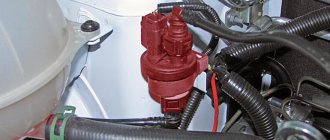
It is attached to the bottom of the shelf under the glove compartment, next to the additional relay and fuse box:
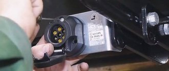
Obd2 connector pinout - diagnostic connector diagram
Obd2 connector pinout - all cars produced in recent years are equipped with all kinds of electronic devices.
One of the important devices is considered to be a system for performing diagnostics of equipment installed in a car. The design of this device includes an OBD2 connector that was designed in the nineties. Its main purpose is the ability to connect a scanner. In addition, it can be used to measure on-board voltage, temperature component, speed, and other parameters. Moreover, all this can be done directly while operating the vehicle. As a rule, the obd2 connector socket is installed in the car near the steering column (the distance is approximately 180 mm). The parametric characteristics of the connector allow you to create an exchange of information data using an industrial digital CAN bus. It is with the help of the CAN protocol that you can connect various control devices, all kinds of sensors and mechanisms. Moreover, you can simultaneously receive and transmit data in digital format at high speed, and there is also an anti-interference function.
Connector design
The functionality and pinout of the obd2 connector is made according to a two-component circuit without symmetry and includes sixteen knife-shaped contacts. These contacts are located in the block parallel to each other with a guide key. Their numbering in the block is done from left to right, with the top line of contacts indicated by numbers 1-8, and the other row with 9-16. The connector design is made of durable plastic, and the contacts themselves are separated by a special longitudinal plate.
To ensure correct polarity when connecting the male connector to the female socket, a trapezoidal design with slightly rounded corners is provided. The functions of the contacts in the connector have two groups of assignments. One of which is made according to a standard design, and the manufacturer has the right to use the other group at his discretion to perform certain tasks.
The wiring of the obd2 connector with the definition of the function of each contact is shown in the table below:
| 1 | Branded |
| 2 | J1850 bus |
| 3 | Branded |
| 4 | General grounding |
| 5 | Signal ground |
| 6 | CAN bus |
| 7 | Line K according to ISO 9141-2 |
| 8 | Branded |
| 9 | Branded |
| 10 | J1850 bus |
| 11 | Branded |
| 12 | Branded |
| 13 | Branded |
| 14 | CAN bus |
| 15 | Line L according to ISO 9141-2 |
| 16 | +12 V |
A distinctive feature in the design of the obd2 connector is that it has a socket for connecting the on-board network. And this makes it possible to use scanners without resorting to the use of an additional power supply circuit. Since the advent of the first obd2 connectors, which were only capable of displaying information about an existing problem, a lot has changed. Today, advanced connectors have the ability to extract maximum information about problems. This happens due to the connection of diagnostic devices with electronic modules in the car.
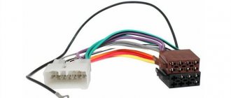
How to make your own connecting cable
Sometimes there is a need to make a connecting wire; this can happen when you need to connect a diagnostic device to a car computer. Therefore, the values indicated in the table will help here in the best possible way.
OBD2 scanner for SsandYong New Actyon
elm327 does not connect to the computer
Due to the increased number of low-quality adapters, if you are faced with the problem that your elm327 adapter does not connect to the car’s ECU, then most likely the problem is that you were sold an adapter with version 2.1 or version 1.5 converted from version 2.1. These adapters use a different Bluetooth module that supports only two protocols out of 6. This is why most often you get a connection with the adapter’s smartphone, but when you try to connect to the car’s ECU, the adapter writes that the ECU is not responding. Here is a short video on a visual comparison of the adapter versions.
If you have an elm327 adapter with an honest version 1.5 where all 6 out of 6 protocols are present, you can be helped by the initialization lines that help the device adapt to the commands of your car’s ECU.
Initialization lines for the Torque and HobDrive programs for cars using non-standard connection protocols. Currently, various diagnostic adapters designed to help the motorist diagnose his own car have become widely popular. The most popular adapters are the elm327 series, which support work with most foreign cars after 1996, as well as domestically produced cars. However, in practice, owners of certain car brands experience difficulties in connecting their car to a diagnostic program that refuses to communicate with the car's electronic control unit. The most common at the moment is the Torque program, so for example, when connecting this program to Japanese market cars produced for domestic use and not having full support for the OBD2 standard, the user is faced with the fact that the program cannot connect to the ECU. In such cases, when your car has a specific unit that one or another program refuses to work with, manually writing an initialization line for the program may come to your aid.
Each car brand uses its own initialization string, in this article we will present the most common initialization strings: - Toyota JDM Nadia/Harrier ATIB96 nATIIA13 nATSH8213F1 nATSPA5 nATSW00 - Toyota JDM 10400baud ATIB10 nATIIA13 nATSH8013F1 nATSPA4 nATSW00 - Toyota JDM CAN mode21 ATSP6 n ATAL nATSH7E0 nATCRA7E8 nATST32 nATSW00 — Toyota GT86 ATSP6 nATAL nATSH7E0 — Toyota JDM ISO9141 ATSP3 nATAL nATIIA33 nATIB10 nATSH686AF1 nATST32 nATSW00 — Toyota JDM Common ATIB96 nATIIA13 nATSH8113F1 nATSPA4 nATSW00 — Toyota Celica ZZT230 ATIB 96 n ATIIA 13 n ATSH 8113F1 n ATSP A4 n ATSW00 — Toyota Vitz 01.2002 ATSH8213F1 n ATIB96 n ATIIA13 — Fiat Pre-OBD ATSH 8110F1 — Nissan Custom ATSP5 nATAL nATIB10 nATSH8110FC nATST32 nATSW00 — Mitsubishi MUT ATSP0 nATAL nATIB10n — Tiggo Delphi MT20U ATSP5 nATAL nATIB10 nATSH8111F1 nATST32 nATSW00 — Delphi MR24 0 ATSP5 nATAL nATSH8111F1 nATWM8111F13E - Siemens ACR167 KWP ATSP5 nATAL nATSH8111F1 n81n - Sirius D42 ATSP5 nATAL nATIB10 nATSH8211f1 nATST32 nATSW00 nATFI - VAZ January ATSP5 nATAL nATIB10 nATSH8110F1 nATST32 nATSW00 - VAZ Bosch MP7 ATSP5 nATAL nATIB10 nATSH8111F1 nATST32 nATSW00 nATFI - VAZ Bosch 7.9.7 ATFI nATALn - UAZ ME17.9.7 ATSP5 nATAL nATSH8110F1 nATFI - Opel KWP2000 ATSP5 nATAL — Japan Domestic Market Nissan ATSP5 nATAL nATIB10 nATSH8110FC nATST32 nATSW00 — Japan Domestic Market Nadia / Harrier ATIB10 nATIIA13 nATSH8013F1 nATSPA4 nA TSW00 — January 5.1.1 ATSP5 nATIB10 nATSH8110F1 nATST10 nATSW00 — January 7. 2 Euro 2 atal natsp5 natib10 natsh8110f1 natst32 natsw00 natfi — VAZ Itelma/ Avtel M73 E3 ATSP5 nATAL nATSH8110F1 nATSW00 - UAZ Patriot Bosch m17.9.7 ATZ nATSP5 nATIB10 nATSH8110F1 nATSW00 - SsangYong 2.3 MSE petrol (Kyron, Rexton, Action, Musso, Korando) atsp5 natib10 natsh8101f3 natst32 n atsw00 — BYD F3 ATSP5 nATSH8111F1 nATSW00 — Toyota Passo KGC1 (1KR-FE) atsp5 natsh8110f0 natfi — Toyota Sienta with ABS atsp4 natal natib96 natiia29 natsh8129f1 natst32 natsw00 — ABS Lifan Solano (wanxiang) ATSP5 nATSH8128F1 nATWM8028F1021080 nATFI — OPEL Simtec 56.5 ATSP5 /nATSH8111F1 /nATSW00 — GREATWALL Delphi MT20U2_EOBD atal natib10 natsp5 natsh8111f1 natst10 natsw00
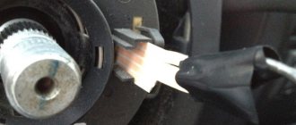
DIY obd1 to obd2 adapter
I made the post for myself, maybe someone will be interested. The adapter from old car models (GM 12 K-Line) was present on basins until 2004, which I did not have. It seems that these “dinosaurs” are all already SCALED, but still some specimens are still alive and in work. The other day a “ten” 2003 arrived, but it was not possible to do diagnostics, because it has a GM 12 socket. I was thinking about making an adapter. The adapter can be ordered here: ru.aliexpress.com/item/Lo….10010208.100010.3.axdn1k for a penny - 270 rubles with delivery, but this is within 3-4 weeks, and you need it today - tomorrow (the adapter was ordered after all) - in principle inexpensive, but as some write: the contacts can be mixed up (+ with -), when connection without dialing, KIRDIK may come to the “cord”
To make an adapter from GM 12 to OBD 2 you will need:
- cigarette lighter plug (for power supply - , + 12V) - 2-wire wire L=20cm - OBD 2 connector from TAZ - 1-core wire L=80cm (K-Line from the cigarette lighter to the GM 12 connector) - end switch “folder” — small (slightly ground down on the sides) — for K-Line pads GM 12
- from the OBD 2 block (pins 4,5) to - (minus) of the cigarette lighter plug - from the OBD 2 block (pin 16) to +12B of the cigarette lighter plug - from the OBD 2 block (pin 7) to the K-Line socket GM 12 (pin M - top left) ————————————————————————————————————————————— —–
Correct wiring of the GM 12 - OBD 2 adapter (the adapter that “arrived” from Ali Express)
:
GM12 connector
Until 2002, injection VAZ 2108-99 were equipped with 12-pin rectangular connectors of the GM12 standard with the following pinout:
- A – “mass”;
- B – L-line diagnostics;
- D – CO potentiometer;
- G – fuel pump control;
- H – +12V power supply;
- M – K-line diagnostics.
Some wires may be missing, but this will not prevent you from conducting diagnostics. The easiest way to read the errors accumulated in the ECU memory is as follows:
- with the ignition off, connect terminals A and B with a jumper;
- turn on the ignition without starting the engine;
- the “Check engine” lamp will display code “12” three times, after which error codes will be issued, also three times each;
- completion of the operation also ends with the code “12”.
The first digit of the code is indicated by the number of “long” flashes of the lamp, the second - by “short” flashes.
Diagnostic connector pinout
Today we will talk about the pinout of the diagnostic connector.
With the advent of electronic control systems from microprocessors in cars, the need also arose to check the operating parameters of the units themselves and the connecting electrical circuits. For this purpose, equipment was invented, called OBD (On Board Diagnostic), initially it only provided information about the malfunction, without any clarification.
In modern cars, using an OBD connector with a standard pinout of the diagnostic connector, you can connect a special adapter or scanner to the on-board computer and carry out a complete diagnosis on your own for almost any motorist. Since 1996, the second concept of the OBD2 standard has been developed in the USA, which has become mandatory for newly produced cars.
Determine the purpose of OBD2:
- type of diagnostic connector;
- connector pinout for diagnostics;
- electrical communication protocols;
- message format.
The European Union has adopted EOBD, which is based on OBD2. It has been mandatory for all cars since January 2001. OBD-2 supports 5 data exchange protocols.
Knowing the location and standard pinout of the OBD2 connector, you can check the car yourself. Thanks to the widespread implementation of OBD2, when diagnosing a car, you can get an error code that will be the same regardless of the make and model of the car.
The standard code contains the X1234 structure, where each character carries its own meaning:
- X is the only letter symbol that allows you to recognize the faulty system (engine, gearbox, electronic components, etc.);
- 1 - represents the general OBD2 standard code or additional factory codes;
- 2 - clarification of the location of the malfunction (power or ignition system, auxiliary circuits, etc.);
- 34 is the serial number of the error.
The pinout of the OBD2 diagnostic connector has a special power plug from the on-board network, this allows you to use any scanners and adapters without additional electrical circuits. If earlier diagnostic protocols showed only general information about the presence of a problem, now, thanks to the connection of the diagnostic device with the electronic units of the car, more complete information about a specific malfunction can be read.
Each connected diagnostic equipment must comply with one of three international standards:
The location of the OBD2 diagnostic connector and pinout for diagnostics can vary greatly from vehicle to vehicle. There is no single standard for location; the car's operating instructions or sleight of hand will help you here.
Errors generated by the ECU
The electronic on-board computer is a complex and at the same time very sensitive device. It is considered a kind of “brain” in the design of any car, as it is responsible for all processes occurring in the systems
Therefore, it is very important to periodically diagnose the “well-being” of your “on-board vehicle” so that all the errors it produces are not ignored
What is an ECU error
As mentioned above, modern control units detect a variety of errors: from a lack of voltage in the network to the failure of a particular mechanism.
In this case, a signal about a malfunction is sent to the driver in encrypted form. All error data immediately enters the ECU memory and is stored there until deleted through a scanner at a service station
It is important that existing errors cannot be deleted until the cause of their occurrence is eliminated
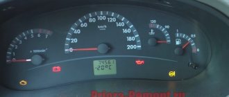
Errors on the VAZ 2107 instrument panel, displayed in the form of icons, are quite understandable to the driver
Deciphering error codes
The VAZ 2107 ECU can detect several hundred different errors. The driver does not need to know the decoding of each of them; it is enough to have a reference book or a gadget connected to the Internet at hand.
Table: list of VAZ 2107 error codes and their interpretation
| Error code | Meaning |
| P0036 | The oxygen sensor heater circuit (bank 1, sensor 2) is faulty. |
| P0363 | Cylinder 4, misfire detected, fuel supply to idle cylinders cut off. |
| P0422 | The efficiency of the neutralizer is below the threshold. |
| P0500 | Incorrect vehicle speed sensor signal. |
| P0562 | Reduced voltage of the on-board network. |
| P0563 | Increased voltage of the on-board network. |
| P1602 | Loss of on-board power supply voltage in the controller. |
| P1689 | Incorrect code values in the controller error memory. |
| P0140 | The oxygen sensor circuit after the converter is inactive. |
| P0141 | The oxygen sensor after the neutralizer, the heater is faulty. |
| P0171 | The fuel supply system is too lean. |
| P0172 | The fuel system is too rich. |
| P0480 | Fan relay, control circuit open. |
| P0481 | Cooling fan 2 circuit malfunction. |
| P0500 | The vehicle speed sensor is faulty. |
| P0506 | Idle system, low engine speed. |
| P0507 | Idle system, high engine speed. |
| P0511 | Idle air control control circuit faulty. |
| P0627 | Fuel pump relay, control circuit open. |
| P0628 | Fuel pump relay, control circuit shorted to ground. |
| P0629 | Fuel pump relay, control circuit shorted to the on-board network. |
| P0654 | Instrument cluster tachometer, control circuit faulty. |
| P0685 | Main relay, control circuit open. |
| P0686 | Main relay, control circuit shorted to ground. |
| P1303 | Cylinder 3, misfire detected, critical for the converter. |
| P1602 | Engine control system controller, power supply loss. |
| P1606 | Rough road sensor circuit, signal out of acceptable range. |
| P0615 | Checking for open circuit. |
Using this table, you can accurately determine the cause of the error signal.
It is important that the on-board computer rarely makes mistakes, so you can safely rely on the received codes