Standards 1DIN and 2DIN
The differences between them are the height of the radios. The number 2 in the designation of the 2DIN standard indicates that the height of a double-DIN receiver is 2 times greater than a device made according to the 1DIN standard. The latest radios are now the most popular and widespread. Installation of double-din radios is not possible in every car, since an appropriate seat must be provided on the front panel.
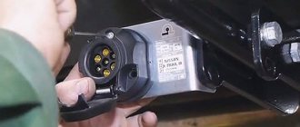
All car radios are divided into two types: with a proprietary connector, most often made in the form of a plug, and located on the rear wall, and with a universal ISO connector. In the first case, you should purchase a proprietary connector for the radio, the pinout of which matches the desired model. If the machine has an ISO socket, then the other end of the proprietary cable should also have an ISO plug. In the second case, the radio is connected directly to the ISO socket located in the car.
When replacing the radio with another one, you should look at the back wall and determine which block is located there. After this, you can decide whether to purchase a proprietary plug or you can connect the device to the machine through an already installed ISO socket. The pinout of the car radio connector is carried out according to the ISO 10487 standard.
Connection diagrams
The cable for the radio, which complies with the ISO 10487 standard, contains cables for the following purposes in the power section:
- adjusting the sound of the car radio depending on the speed (optional, use a cable with any insulator);
- lowering the volume or completely muting the sound when a call arrives on a connected cell phone (optional);
- supplying a positive signal from the car battery to ensure that the settings are saved in the equipment memory (yellow wire insulator);
- positive power supply for the standard antenna (blue wire);
- backlight system for the screen and control keys for the head audio device (orange cable);
- supply of positive power from the ignition switch (red insulation);
- connection to the vehicle ground (cable with black protective coating).
The speaker wiring harness includes the following cables:
- positive and negative terminals of the right rear speaker (purple and violet-black, respectively);
- right front speaker harness (gray and gray-black cables);
- switching of the left front speaker (white and white-black isolator);
- left rear speaker connection (green and green-black cables).
ISO pinout
Many new radios increasingly use a Euro connector. It is a rectangular sixteen-pin plug consisting of one or two equal parts. An ISO plug is installed on the car, allowing you to connect any car radio that has the appropriate connector. The ISO pinout does not depend on the radio model equipped with such a connector.
Upper power connector A
It is used to supply current from the vehicle's on-board network, as well as to remove power from an active antenna or amplifier, to mute the sound and supply a backlight control signal. According to the standard, wires are marked by color:
- yellow - direct connection to the vehicle’s battery; it also supplies power to the receiver’s RAM, which provides storage of settings specified by the user;
- red - it supplies the main power;
- black is ground, the negative pole connected to the GU body;
- blue with a white stripe - when the car player is turned on, 12 V is supplied to the active antenna amplifier or the remote control controller of the car audio power amplifier;
- orange - a signal is sent to it from the vehicle’s side light switch to control the backlighting of the keys and display;
- brown - used to mute the sound, for example, while talking on the phone.
It is worth considering that two power supply systems are used. In the first case, the yellow and red wires on the pinout are connected together. The power supply to the radio does not depend on the position of the ignition key.
If you leave the car player on without a protection timer, the car battery may quickly drain.
The second system involves connecting the red wire through the ignition switch, and the yellow wire directly to the on-board network. Thanks to this, the power supply to the radio is connected to the position of the key. When the ignition is off, you can remove or insert the CD. It also keeps the audio system's built-in clock running and saves settings such as sound settings and radio channels.
The pinout of the ISO connector of the radio, intended for power supply, is carried out as follows. Pins 1, 2 and 3 are reserved and are used by some head units to enable additional functions. Pin 4 is connected to the yellow wire, and pin 5 is connected to the blue/white wire. An orange wire is connected to pin 6. Pin 7 is connected to the red wire, and pin 8 is connected to the black wire. This connector is often painted brown.
Bottom speaker connector B
It is used to supply amplified sound from the car player to the speakers. The wires through which alternating current directly flows from the microcircuit are solidly colored, and the wires connected to ground have black stripes. Color marking is carried out as follows:
- the white wire connects to the left front speaker;
- the gray wire connects to the right front speaker;
- the green wire connects to the left rear speaker;
- The purple wire connects to the right rear speaker.
Markings and types of connectors
To answer your silent question about what kind of connectors there are in car radios, I must answer that most modern car radios are equipped with two standard connectors, designated by the abbreviation “ISO”. Each of these connectors is designed as an eight-pin rectangular plug, sometimes they are combined into one housing (see photo).
Car radio ISO connector pinout
One of the connectors carries “power” circuits, that is, current consumption sources are connected to it, and is designated in the diagrams as a connector under the letter “A” and is colored brown. The second connector is intended for connecting the car’s acoustic system, in other words, speakers. Unlike the previous one, it is made in black and is designated on electrical circuit diagrams as connector “B”.
What connectors do car radios have?
Sometimes there are car radios with three connectors, but this is the exception rather than the rule. The same exception as non-standard connectors, which still have wiring with standard markings and in any case allow you to connect the wires of a standard speaker system with non-standard “connections” in at least two ways. So:
- “Skolkhoz”, namely, cut off the non-standard plug and overlap the wires, which “is not very good”, since over time the twist will become loose due to oxidation/shaking and, in the best case, you will have to do all the work again while simultaneously replacing the fuses.
Pinout of ISO connectors for car radios
- Buy an adapter (the price of which is in no way close to the amount of work that the method described above includes) and, without any problems, decorously/nobly, connect the car radio with other elements of the acoustic circuit of your car.
The choice of adapters at the moment is huge, and it is simply physically impossible for any troubles to arise in the use of this variety.
Car radio ISO connector pinout
Pinout diagrams for radio tape recorders from popular manufacturers
Wiring of linear outputs on a standard radio can be done using two RCA connectors. This option is the most common, since power amplifiers have the same sockets. The pinout of connectors for Pioneer car radios contains from 10 to 20 contacts. Their purpose depends on the model of the multimedia device. For example, in the KEH series, the first pin is the antenna control, the second pin is the voltage from the ignition switch, etc. The speakers are connected to pins 3, 4, 5, 6, 8, 9, 10 and 11.
Many motorists are faced with the need to replace the head unit. The process requires a radio pinout and a guide for connecting the audio system.
What is an ISO connector for a car radio?
- What is ISO
- Standard connection diagrams
- Standards 1din and 2din
- Dual ISO connector
- If the car radio is without a plug
- Adapters for ISO connectors
When connecting car radios themselves, vehicle owners are often faced with the need to select a part such as an ISO connector. To avoid errors and additional costs, it is worth understanding the features of this device in advance.
Pinout of a standard Euro connector
The Euro connector is a standard plug for many modern devices. An ISO plug is installed on the machine, thanks to which it becomes possible to connect any model of radio with the appropriate connector.
Standards 1DIN and 2DIN
The difference between the standards lies in the size of the devices: a 2-din device is 2 times higher than a 1-din device.
The most common are 1-DIN radios, because Installation of higher devices due to the lack of a seat of appropriate size on the front panel of the car is not possible in every car.
There are 2 types of radio tape recorders:
- With proprietary connector. You need to choose a product whose pinout matches the desired car.
- With universal connector. The device connects directly to the ISO socket provided in the car.
Pinout is carried out according to ISO 10487 standard.
Upper power connector A
The connector serves as a connector between sources and consumers of electricity from the on-board network.
Plugs 1, 2, 3, 6 are rarely used in radio circuits of the lower and middle price segments. The elements are used when connecting additional options in higher quality player models. Wire colors may vary.
You should understand the purpose of the contacts:
- ANT. Used with a retractable antenna.
- Remote. Designed for connecting external amplifiers. Thanks to it, you can increase the number of mounted speakers, which is necessary in the interiors of large cars.
- Illumination. Adjusts the brightness of the player screen (the higher the driving speed, the less intense the backlight, so as not to distract the driver).
- Mute. Adjusts the sound of the device.
- A4. Turns the audio system on and off.
This connection scheme allows you to protect the battery from discharge, because turning on the system is possible only when you turn the ignition key, while the acoustic cascades consume electricity even when turned off.
The pinout of the ISO connector of the radio (European) looks like this:
- Connector A5 (blue) is for the antenna. If the permissible current value (300 µA) is exceeded, both the amplifier stages and the entire head unit may break.
- Wire A7 (red) is intended to power the head unit. When it is disabled, the settings are returned to factory settings. Voltage - 12 V.
- Cable A8 (black). Responsible for connecting the speaker system to the car.
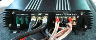
To protect the audio system, the wires must be equipped with a fusible link. If interruptions occur in the operation of the player, you should place a capacitor between connectors A7 and A8, which will act as a filter, smoothing out fluctuations in the electrical circuit.
Bottom speaker connector B
The speakers are connected through it as follows:
- Rear right + (purple).
- Rear right - (black and purple).
- Front right + (gray).
- Front left - (black and gray).
- Front left + (white).
- Front left - (black and white).
- Rear left + (green).
- Rear left - (black and green).
Most devices are designed for 4 channels; 8 wires are used for this (2 pieces per speaker).
The sound quality of the system depends on the “flattening”. If you mix up the connectors, the device will not fail, but the radio will not work correctly.
Audio system elements should be connected with cables with a cross-section of 1.5 mm or more. Thicker wires are used on power lines.
Standard pinout of the Prology car radio ISO connector
- Purple wire - increases the sound of the right rear speaker.
- Purple, black - decrease the level of the right rear speaker.
- Gray wire - increase the volume of the left rear speaker.
- Gray, black - decrease the sound on the rear left speaker.
- White wire – increases the sound of the left speaker (front).
- White, black – sound on the same speaker.
- Green wire - increases the sound of the right front speaker.
- Green, black - reduce the volume of the left front speaker.
- The yellow wire is powered from the car battery.
- Orange—backlit control keys.
- Blue and white - antenna power.
- The red wire is the ignition switch.
- Black wire - minus (ground).
Connections for some car models and receivers may vary slightly. To what extent these differences are fundamental and can affect the connection of sound-reproducing equipment, you can judge after reading the description of the pinout using the example of a car radio from the Pioneer brand.
Pioneer radio ISO connector pinout
When buying a used car, many drivers want to replace the standard radio (Prolozhi) with a device of a higher level (Pioneer). And they are faced with such a problem as mixed up wiring on homemade twists or with connectors that are not suitable for the Pioneer.
The way out of this situation is quite simple (at least in words). To do this, you just need to purchase an ISO standard connecting device and pin it out according to our recommendations. Due to the fact that all modern car radios have standard ISO connections and rectangular plug boxes on the rear panel, there should be no problems with the connection after pinout.
So, the pinout of the ISO connector of the car radio through 2 Pioneer blocks is done in this way:
- Block with upper contacts, letter B.
- Increase (decrease) the sound reproduction level. The color of the electrical wire is any.
- The wire that mutes the sound, for example, when there is an incoming phone call, etc., is also a free color.
- ACC mode (connected to the car ignition, + appears when you turn the key and disappears when turned off), yellow color.
- Twelve-volt power supply for the radio antenna - blue wire.
- The orange wire is responsible for illuminating the display of the car player.
- Car ignition - red wire.
- Ground – wire with black insulation.
- Bottom junction box - A.
- + right rear speaker of the multimedia system - purple wire.
- Minus - black, purple wire for the left speaker.
- Front right speaker, volume increase—gray wire.
- Right front column. Reduction - black, gray wire.
- The left column (front), plus - the wire color is white, negative - black and white wires.
- Both speakers located at the back (increase, decrease volume), green and a combination of black and green.
Since 2000, some manufacturers of European passenger cars (BMW, Ford, Mercedes, Peugeot, etc.) began to use a 40-pin Euro connector called Quadlock or Fakra. At the same time, the pinout according to wire colors remained the same for the main (named) functions.
Pinouts for various brands of cars and radios
The wiring of the linear outputs on the standard radio depends on the make of the car and the head unit.
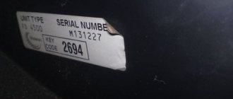
Before pinouting the connectors of the car radio, you must read the information presented on the cover of the device and in the instructions for it.
Toyota
For a standard plug: 1 - A+, 2 - GND, 3 - BAT+, 4 - backlight, 5 - antenna adjustment, 9-16 - speakers (RR+, RR-, RF+, RF-, LF+, LF-, LR+, LR -).
Universal connector for most models: 1 - ANT, 3 - linear output LR, 4 - GND linear outputs, 5 - linear output RR, 6 - CD in LCH, 7 - CD in GND, 8 - CD in RCH, 9 - CD reset , 10 — CD clock out, 11 — CD DSPL select, 12 — CD data out, 13 — CD clock in, 14 — CD data in, 16 — A+, 17 — GND, 18 — ANT GND, 22-27 and 29- 30 — speakers (LF-, LR+, RF-, RR+, LF+, LR-, RF+, RR-), 28 — CD mute, 31 — ANT CONT, 32 — CD ACC CONT, 33 — AMP CONT, 34 — B UP .
What is ISO
The ISO connection intended for the car radio is a plug that meets Euro standards. With its help, the audio system is connected to the car electrics.
Most manufacturers produce plugs equipped with 2 connectors, each with 8 pins. For ease of connection, the connectors are color coded. The gray (or brown) radio connector is intended for connection to a voltage source. It is denoted by the capital letter “A”. The second connector (designated “B”) is painted black. Wires from the speaker system or speakers are connected to it.
Some models may be a single product consisting of 16 line outputs on the car radio. This ISO connector of the radio is different in that 2 connectors are combined into one design.
Are you a car driver?! Then you can take this simple test and find out. Go to test »
Adapters for different connectors
The elements are designed to connect the car radio to the car's electrical network using various plugs. Often, adapters are equipped with ISO connectors on one side, and on the other, a non-standard proprietary connector suitable for a particular car model.
Using such elements, you can mount speaker systems with Euro connectors instead of devices with original plugs, and there is no need to re-solder the conductors or any other intervention in the machine’s electrical network. On sale you can find products with 2 non-standard plugs.
Sometimes the car is not equipped with connectors, then you need to connect the plug suitable for the radio to the wires in the car. This is done both by twisting and soldering. A terminal block is also used for this purpose; additional insulation is not needed in this case. When twisting and soldering, you will have to use cambrics or heat-shrink tubing to ensure safe use of the device.
Adapters are used to connect:
The advantage of using the elements is that there is no interference with standard wiring: the user does not have to solder or cut wires.
On devices with the option of control from the steering wheel of the car, a button adapter is provided - another type of adapter. It is a special device with which you can replace the standard audio system with other equipment.
Connector pinout (decoding)
The connector pinout is the only element of the power interface that has an individual circuit. In other words, the interface is always different and depends on the specific model of the radio, but the pinout designation of the radio is always the same. The description is usually given in the documentation.
Connector pinout
There are methods for determining pin outputs experimentally if it is impossible to obtain an original description of the contacts. This is typical for Chinese devices produced under fly-by-night brands. The need for restoration is often necessary, since the device turns out to be of really good quality and can still be used for media purposes.
Detailed description of connectors
Description of control connectors
The operating instructions contain the usual diagram with symbols, the description of which is given below. The data should take into account the names of the radio contacts that are located on the rear panel. There is no universal option, since the more interfaces, the more extensive functionality is supported. Pioneer practices a large number of interfaces, others do not.
But quantity is not a panacea, but only one of the options for interface elements. The best way to understand what has been said is with the help of an illustration showing connectors for ToyotaPrado. The designations on the pinout are described in the instructions for the radio and are given below.
Name of wires and power outputs of the car radio
| BAT, K30, Bup+, B/Up, B-UP, MEM +12, BATTERY | Battery powered |
| GND, GROUND, K31, minus | Wire to ground |
| A+, ACC, KL 15, SK, S-kont, SAFE, SWA | Power supply from ignition |
| N/C, n/c, N/A | Blank contact |
| LAMP, 15b, Lume, iLLUM, K1.58b, “sun”. |
In some cases there are two wires -iLL+ and iLL
The above list is not exhaustive. Car radio interfaces are the concern of manufacturers, so the decoding of the wires is always individual and is given in the instructions for each car radio. Contacts, as already mentioned, and their number depend on the functionality of the car radio and control features, and therefore are considered the prerogative of the manufacturer.
Pinout
Explaining in accessible language which color wire is responsible for which function in the device. The pinout can be presented as:
- graphic diagram;
- tables.
Description in free form. It is this form of representation of the pinout of car players from Pioneer (Prology 1715t), Sony, Kenwood, Hyundai, JVC, Mystery) that we will use in this information article.
ISO connector is a contact technical device for connecting electrical wires along their groups of eight contacts (16), in two or one rectangular housing.
The brown block connects the wiring for the speaker system and sometimes its control (control of changing radio stations or musical compositions from the steering wheel of a car).
Black block - power (electrical) supply of contacts between the car and the sound-reproducing device.
Sometimes the contacts are combined in one connector, and they are separated into groups in the upper and lower parts of a single housing. ISO is a generally accepted technical standard for goods and services developed by an international organization for standardization.
ACC is a connection that allows you to listen to music and radio without starting the car.
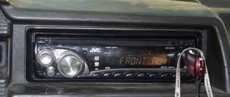
How to connect an LG radio
Car radios belonging to the LG family have always been very reliable. In addition, the sound quality that was reproduced with their help was also of the highest level. However, long-term operation of such a device is only possible if you follow all the rules for its operation (they are described above). In addition, you should also perform the installation technology correctly. Connection and can be reproduced with your own hands in two ways.
Method one
So:
- First you need to see if the ignition is turned off. You also need to disconnect the terminals from the battery power supply.
Note: With these simple maneuvers you can avoid short circuits in the circuit. This will save not only the radio, but the entire car as a whole.
- Now you need to remove the old receiver, which was previously installed in the standard hole.
- Install the mounting casing into the freed hole. It is included with the new device.
- In order for this casing to be securely fixed, the fasteners must be bent, otherwise the radio will wobble.
- Connect the head unit using standard ISO plugs.
Note: sometimes such a plug may suddenly not be available in the car. In this case, installation may take a little longer, since you will have to figure out which wire goes where.
Standard connector for LG car radios