All modern machines use electrical sensors for stable operation of the units. One is responsible for turning on the radiator fan, the other monitors the oil level. An electrical element is also responsible for the internal combustion engine, and sometimes it can be difficult to figure out which indicator affects engine starting, especially in winter. Sometimes it is one of them that becomes the reason why you cannot use a car during the cold season.
Here you will find information on how to warm up the engine in cold weather.
What sensors are installed on the engine
The number of electrical sensors that control the operation of units varies in each car. Even for the same model, it may vary depending on the following factors:
- year of car manufacture;
- equipment;
- installation or removal of additional equipment;
- region of production of the car.
The more control over the performance of the car is given to the on-board computer, the more controlling electronic systems there will be under the hood. To display information on the on-board computer monitor, a special monitoring device is required.
As a rule, this is a metal rod, which, due to magnetic fields, reacts, for example, to the number of rotations of the measured element. Some sensors operate on the principle of thermodynamics and resistance of materials, alternatively due to the expansion and contraction of a metal base.
Here you will learn about the engine glow plug heating system.
Not all electrical sensors affect the start of the power unit. There are connections between the motor and other units, and control elements may not allow the engine to start if they are faulty.
Attention! To determine which sensor affects engine starting in winter, you first need to understand what kind of indicators are installed under the hood.
How to start a car 100% in winter
The worst case scenario is to frantically crank the starter until the battery runs out. Then ask for a “light” and try to start the “flooded” engine until the starter breaks down. After that, start starting it with a tug. The result may be a damaged expensive converter, an exploded muffler, or an intake manifold.
Therefore, even before the cold weather sets in
:
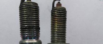
- If the time is right, we will change the oil, filters and spark plugs;
- Let's clean the battery terminals, check it with a load fork;
- We will buy a cylinder of “quick start” ether in advance;
- We will choose high-quality wires for lighting.
Let’s make it a rule in the evening, 10 minutes before the end of the trip, to turn off the heated windows, powerful audio system, and excess lights. This will help the battery store a little more electricity.
In order not to harm the car during an emergency start, we use simple rules.
- Do not panic, use the starter for a maximum of five seconds. Try to start again after at least 2-3 minutes.
- If after two or three manipulations the engine does not start, we will ask an experienced neighbor to “give me a light” to support the battery. Let's try 2 more times.
- The engine is silent - we spray ether into the inlet pipe. This must be done carefully, after consulting with a specialist. They will show you where to spray so as not to damage the sensors. Let's try two more times.
- If we fail again, we leave to warm up and return to the car an hour later to repeat the procedures. If the result is disappointing, call a mechanic we know or a special service.
In this article, we kept silent about the methods of calcining spark plugs, pouring boiling water over the manifold, replacing temperature sensors with resistors, reading readings through the diagnostic connector - only the most experienced car enthusiasts can do this. Therefore, in order to start a car 100% in winter, you need to keep it in good condition.
Modern cars are designed for use at temperatures down to -25 degrees and start confidently in such frosts.
If frost finds you outside the city, and there is nowhere to wait for help, go out into the yard every 4 hours and warm up the car to operating temperature. Or entrust this work to an alarm system with auto start. In calm weather, a car blanket will help keep you warm. If your security system model does not have autostart, and you are confident in safety, leave the engine running overnight. Then in the morning you are guaranteed to be able to leave on your own in any frost.
But remember!
Exhaust gases are very toxic, so never leave a running engine in a closed garage or other area without ventilation.
If problems arise with the engine, you may be asked which sensor is responsible for engine speed. Often it is these electronic devices that drivers are guilty of in the first place. But the sensors should be checked last. The speed can fluctuate for a variety of reasons. First you should make sure there are no other damage.
Often problems with speed begin after refueling with low quality fuel. In this case, the injection system is simply not able to produce a normal mixture.
As a result, the revolutions begin to float. Another reason is an ignition fault. This is also a fairly common problem. Only after eliminating all these reasons can you proceed to checking the sensors.
Where to look for a breakdown?
Which sensor is responsible for engine speed?
The answer to this question is both simple and complex at the same time. The reason may be in 4 different sensors:
- (DHH);
- (DPDZ);
- (DFID);
- Exhaust gas recirculation ().
Also, in very rare cases, the cause of floating speed may be the crankshaft position sensor. But this happens extremely rarely and we will not consider this option here. Typically, problematic sensors are identified during computer diagnostics. But sometimes it is not possible to visit the service for this procedure. Therefore, you can completely do it yourself to check them. Idle speed sensor
It should be noted that if it is damaged, the speed will float mainly at idle. But in any case, the check should begin with DXX. To do this, you need to remove the wire block from the sensor. Then the voltage is checked. To do this, one terminal of the wires is connected to ground, that is, applied to the engine. The second wire is connected to the sensor and the voltage is measured.
The multimeter must output a voltage of at least 12V. If the indicator is lower, then the battery may be low. After its charge is restored, engine operation may be restored. You also need to check the resistance at the terminals, it should be 53 ohms. Measurements must be made on paired contacts. You need to change the sensor if the resistance is lower or higher.
On throttle position
This sensor is designed for the controller to calculate the throttle opening level. It is installed on the throttle axis. When you press the accelerator pedal, it turns along with the throttle. Essentially, this is a variable resistor that, depending on the angle of rotation, changes the voltage level supplied to the controller.
It is checked this way. The ignition is turned on and the voltage at the sensor terminals is measured. It should fluctuate from 0 V at the starting position, to 12 V at the maximum. You can also measure resistance, but this is not necessary. If the voltage is absent or increases unstably, then the TPS is faulty and needs to be replaced.
Mass air flow sensor
This sensor controls and normalizes the flow of air into the fuel mixture. Signs of its malfunction are the following problems:
- Unstable speed;
- Problems starting a warm engine;
- Reduced power.
This sensor is checked in different ways. The simplest of them is to turn off the mass air flow sensor and drive without it. If the negative aspects disappear, then most likely the reason is in the sensor. Also, sensor failure can be caused by poor-quality firmware. To do this, place a 1 mm thick plate under the throttle valve stop. At the same time, the speed should increase slightly. Then remove the chip from the sensor we are interested in. If the engine continues to run, the reason is the “crooked” firmware. The test is also performed by measuring the voltage. To do this, take a multimeter; it should be set to a maximum voltage of 2 V. Next, measure the voltage at the terminals. On a new, fully operational sensor, it should fluctuate between 0.98-1.01 V. A malfunction of the mass air flow sensor is indicated by a voltage of more than 1.05 V. In this case, it should be replaced.
Store currency is rubles. wmz wmu
Types of automotive electrical and thermodynamic sensors
A special electrical system monitors the quality of gasoline or diesel fuel. However, this is not a common phenomenon, and this system is not installed on all machines.
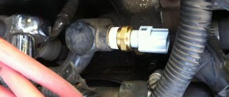
A separate component with a regulating sensor is responsible for the coolant temperature. Very often, it is its breakdown that leads to failure to start the engine.
The idle speed sensor regulates the amount of fuel entering the combustion chamber when the car is standing still, but with the engine running.
The throttle valve, which regulates the flow of air into the combustion chamber, is also controlled by a sensor. More precisely, its position must correspond to the parameters built into the system. If its operation is disrupted, the mixing of air with fuel also does not work correctly, which leads to the inability to start the car.
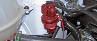
A so-called flow meter is installed on the air hose from the air filter. This incoming air mass flow sensor monitors the amount of oxygen entering the powertrain. When it is faulty, too much oxygen begins to flow into the engine, and the engine will run poorly or will not start at all.
The starting of the car is also affected by the knock indicator. It is located on the top of the internal combustion engine and is responsible for vibrations. When the force of detonation becomes detrimental to the engine, the smart sensor will let the electronic control unit know about it, and the oxygen supply will be blocked. As a result, the fuel-air mixture will not ignite from the spark plug and the engine will stall. This is unpleasant for the driver, however, this action will definitely protect the owner’s wallet, since the entire motor will not have to be repaired or replaced.
Another indicator monitors the correctness and speed of the crankshaft. As soon as its position is violated, a command is sent to the electronic control unit, which immediately blocks the operation of the car. This prevents the motor from serious damage. Otherwise, if the power unit continued to operate, the valves inside would be bent and, most likely, the mounting sockets would be damaged. In this case, the engine will have to be sent for scrap.
It's all about the car's information sensors.
All processes for starting the engine are controlled directly by the electronic control unit of the power unit. This is where information flows from all the sensors responsible for the operation of the motor. This center operates algorithms for distributing the load on the internal combustion engine. If all components of the electrical circuit are working properly, but the car does not start, the reason may lie in the main control device - the engine ECU.
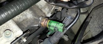
ENGINE COOLANT TEMPERATURE SENSOR
The engine coolant temperature sensor is a relatively simple sensor that monitors the internal temperature of the engine. The coolant inside the cylinder block or cylinder heads absorbs heat from the cylinders when the engine is running. The sensor detects changes in temperature and signals the Electronic Control Unit (ECU) about the state of the engine - the engine is cold, warming up, overheated or operating at normal temperature. This sensor is very important and is considered one of the main ones, since the signals it sends to the ECU affect the overall behavior of the engine management system. Engine operating temperature affects many fuel, ignition, exhaust and transmission functions that are controlled by the ECU. Depending on the engine temperature, its operating mode is selected. This can improve cold engine drivability, idle speed and exhaust emissions. Therefore, if you see on the screen that the engine coolant temperature sensor is faulty or is reporting incorrect data to the ECU, this can lead to many problems.
INFLUENCE OF COOLANT TEMPERATURE SENSOR ON ENGINE OPERATION
The sensor signals can be used by the ECU to perform the following control functions: * Fuel enrichment in engines with fuel injection. When the ECU receives a cold temperature signal from the sensor, it increases the pulse duration to the injectors to enrich the fuel mixture. This improves engine idling and prevents hesitation when warming up. As the engine approaches operating temperature, the ECU leans the fuel mixture to reduce fuel consumption and exhaust emissions. A malfunction of the sensor, from which cold temperature signals are always received, can cause over-richness, contamination and loss of the fuel mixture. Constant overheating warnings can cause poor drivability when the engine is cold, such as stalling, hesitation and rough idle.
* Ignition advance and retard. The ignition timing must be strictly adjusted to reduce the amount of exhaust gases until the engine temperature reaches normal. This also affects engine performance and fuel consumption. * Exhaust gas recirculation during warm-up. For optimal drivability, the EGR valve should not open until the engine is fully warmed up. EGR when the engine is cold can cause rough idle, stalling and/or hesitation. * Purge the filter of the fuel vapor recovery system. To ensure optimal controllability, the carbon filter, which collects fuel vapors, should not be purged until the engine is fully warmed up. * Regulation of the composition of the fuel mixture in closed/open feedback loop modes. The ECU may not take the oxygen sensor feedback into account until a certain coolant temperature is reached. While the engine is cold, the ECU will remain in open loop (no feedback) mode and keep the fuel mixture rich to improve cold engine idling and drivability. If the ECU does not go into closed-loop (closed loop) mode after the engine warms up, the fuel mixture will be too rich, resulting in fouling and loss of fuel, as well as fouled spark plugs. * Idle speed during warm-up. To prevent stalling and improve idle speed, the ECU usually increases the idle speed when the engine is first started. * Locking of the transmission torque converter clutch during warm-up. To ensure optimal drivability, the ECU does not lock up the torque converter until the engine is fully warmed up. Electric cooling fan operation. Based on signals from the coolant temperature sensor, the ECU controls the engine temperature by turning the cooling fan on and off - this is necessary to prevent engine overheating. Note: On some vehicles, the second coolant temperature sensor or coolant switch may be used exclusively for the cooling fan circuit.
TYPES OF COOLANT TEMPERATURE SENSORS
Most coolant temperature sensors are thermistors whose resistance changes as the coolant temperature changes. These are basically negative TCR (temperature coefficient of resistance) thermistors, in which the resistance drops as the temperature rises and rises when the engine is cold. As the engine warms up, the internal resistance of the sensor drops until it reaches a minimum, and the engine begins to operate at normal temperature. A typical coolant temperature sensor, for example, has a resistance of 10,000 ohms at 32 degrees F and drops to 200 ohms as the engine warms up (200 degrees). For comparison, the same sensor manufactured by , may have 95,000 ohms at 32 degrees and drop to 2,300 ohms at 200 degrees. The standard resistance may vary for different cars, so do not rush to replace every sensor whose readings are outside the norm. Coolant temperature sensors have two wires: input and return. The ECU sends a reference voltage signal of 5 volts to the sensor. The sensor resistance reduces the voltage signal and sends it back. The ECU calculates the coolant temperature based on the voltage value according to the feedback signal. The coolant temperature reading is displayed on the scanner, as well as on the instrument panel and driver information screen. In some cases, dual-function coolant temperature sensors are used. When the coolant temperature reaches a certain level, the ECU changes the sensor reference voltage so that its readings are more accurate (high resolution). Some older vehicle models may use other types of coolant temperature sensors. These are mainly sensors with a two-position switch that open and close at a certain temperature. This sensor is either directly connected to a relay to turn the cooling fan on and off, or it sends a signal to the instrument panel, causing the warning light to come on. These sensors, usually single-wire, send a signal to a meter on the dashboard.
Good day! The problem is this. In cold weather with a half-dead battery (by the way, it started easily if you parked it in the evening and picked up the car in the morning without removing the battery) after 3 days of parking, I filled the spark plugs. The battery froze in the garage. Unscrewed it. I also bought a set of new ones as a spare. I dried the old ones on the tiles. The car is parked in an iron garage. Today it is -19 outside. In the garage I think it’s 4-5 degrees warmer. Heated up the garage with a blowtorch. It got really warm. I rowed for an hour and a half. The engine did not warm up. I thought, since there was already dripping from the ceiling in the garage, I wouldn’t heat the engine with a lamp. But it still wouldn't start. He sneezes, there is a faint smoke coming out of the chimney, and that’s all. The battery was discharged to “0”. I'm charging now. I screwed in both new and old spark plugs. It fills and that's it. Then I noticed that the expansion tank was empty. I shined the light on the carrier and saw what was coming out from under the pump. There is antifreeze in the radiator. Could this affect the launch? PS. I bought antifreeze. I'll go top it up now.
Sensor malfunctions
If the sensors malfunction, the engine does not always refuse to start. He may be working, but he is behaving “inappropriately.” The behavior of the motor can be different, and each incorrect action of the power unit has its own reasons, which may also lie in the malfunction of certain sensors.
Sometimes the engine starts, but at the same time it begins to, as they say, “triple”: the engine speed arrow “walks” and does not maintain exactly the required number of crankshaft rotations. The cause of the violation may be the failure of meters associated with the flow of air into the engine and the position of the camshafts, as well as the operation of the electronic control unit of the power unit itself.
When the engine does not start at all, this may be due to any sensor. It's difficult to say exactly. Therefore, to identify a malfunction, it is necessary to check each sensor for functionality, as well as the wiring suitable for them. In addition, computer diagnostics can indicate the problem.
The reason for failure to start the engine may be the failure of a number of indicators at once. It will be possible to identify violations by connecting to the machine via a computer and step-by-step elimination of identified faults.
Sometimes the engine starts, however, after some time or periodically it may stall. This is usually due to a malfunction of the following sensors:
- throttle position;
- mass air flow;
- crankshaft position;
- oxygen sensor;
- idle speed controller.
IMPORTANT! Failure to start the engine is not always due to faulty sensors. It is best to first check their performance and only then deal with the mechanical component of the breakdown, if the diagnostics of the electrical components did not reveal any problems.
For stable engine operation and timely detection of faults, many sensors work in the car. The principle of their operation begins with the simplest ones, designed to fix the emerging magnetic field at a strictly regulated moment or expand the metal core to a certain value, and ends with a separate microcircuit, which contains a strict algorithm of actions during the manifestation of processes.
Here you will learn about oxygen dots and their common malfunctions.
It is thanks to these electronic systems that we can control the car, and the car works even in extreme conditions. Manufacturers have tried to use indicators to make life easier not only for car owners, but also for mechanics. Thanks to electronic systems, it is possible to quickly identify a malfunction using computer diagnostics and view the procedure for eliminating the problem.
Most often, the engine does not start or runs intermittently precisely because of the failure of some sensor, which, by the way, due to the simplicity of its design, breaks extremely rarely. In order to quickly understand the cause and immediately eliminate it, it is best to seek help from computer diagnostic specialists. By connecting to the car using specialized software, diagnosticians will immediately identify the problem and understand what to start with when making repairs.
Knock control device
It is mounted directly on the power unit block, located between the second and third cylinders. There are the following types of devices:
-
- • resonant - has a cylindrical shape;
- • wide-flat - flat in shape.
The device works on the principle of a lighter with a piezo element - the voltage increases with the force of the impact. The sensor monitors sounds in the power unit that indicate detonation. If there are any, the ignition does not fire immediately, but a little later.
If the sensor malfunctions, the engine starts to run slower and fuel consumption increases.
Location of Skoda Octavia engine management system sensors
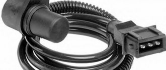
The inductive type crankshaft position sensor is designed to synchronize the operation of the electronic control unit with the TDC of the pistons of the 1st and 4th cylinders and the angular position of the crankshaft. The sensor is installed at the rear of the engine block. As the crankshaft rotates, the sensor's magnetic field changes, inducing alternating current voltage pulses. The control unit uses sensor signals to determine the crankshaft rotation speed and issues impulses to control the engine. A malfunction of this sensor causes a complete failure of the engine control system: in the absence of its signal, the engine cannot be started.
The oxygen concentration control sensor is used in a closed-loop fuel injection system. To adjust the calculations of the duration of injection pulses, information about the presence of oxygen in the exhaust gases is used; this information is provided by the control oxygen sensor. Oxygen contained in the exhaust gas reacts with the sensor element, creating a potential difference at the sensor output. The potential difference varies from approximately 0.1 V (high oxygen - lean mixture) to 0.9 V (low oxygen - rich mixture). The oxygen concentration control sensor is installed on the exhaust system manifold. For normal operation, the temperature of the sensor must be at least 300 °C, therefore, for quick warm-up after starting the engine, a heating element is built into the sensor and the engine is additionally equipped with an additional air supply system, the main purpose of which is to ensure exhaust toxicity standards during a cold engine start. Monitoring the output voltage of the concentration sensor oxygen, the ECU determines which command to adjust the composition of the working mixture to send to the injectors. If the mixture is lean (low potential difference at the sensor output), then a command is given to enrich the mixture; if rich (high potential difference) - command to lean the mixture.
The diagnostic oxygen concentration sensor is installed after the neutralizer, works on the same principle as the control sensor, and is completely interchangeable with it. The signal generated by the diagnostic oxygen concentration sensor indicates the presence of oxygen in the exhaust gases after the converter. The efficiency of the neutralizer is assessed by the engine control unit by comparing the signals from the control and diagnostic sensors. If the converter is operating normally, the diagnostic sensor readings will differ significantly from the control sensor readings. The same readings indicate a malfunction of the converter.
The intake manifold absolute pressure and temperature sensor detects changes in pressure and temperature in the intake manifold depending on changes in load and engine speed and converts it into an output signal voltage. Depending on the information received from the sensor, the ECU regulates the amount of fuel injected and the ignition timing.
The inductive type camshaft position sensor (phase sensor) is installed at the rear of the cylinder head behind the throttle assembly. As the camshaft rotates, protrusions on its timing disc change the sensor's magnetic field, inducing alternating current voltage pulses. The sensor signals are used by the ECU to organize phased fuel injection in accordance with the firing order of the cylinders. If a malfunction occurs in the camshaft position sensor circuit, the ECU stores its code in memory and turns on the signal pump.
The coolant temperature sensor measures the temperature of the coolant and sends a signal to the control unit. The sensor is made in the form of a thermistor, sensitive to temperature changes. The electrical resistance of the sensor decreases with increasing temperature. The ECU processes the sensor signal and sets the optimal enrichment of the working mixture when the engine warms up.
The knock sensor is attached to the top of the cylinder block on the intake pipe side and detects abnormal vibrations (knock knocks) in the engine. The sensitive element of the sensor is a piezocrystal plate. During detonation, voltage pulses are generated at the sensor output, which increase with increasing intensity of detonation impacts. The ECU, based on the sensor signal, adjusts the ignition timing to eliminate fuel detonation flashes.
The throttle position sensor (TPS) is installed on the side of the throttle assembly (under the cover) and is connected to the throttle axis. It is a potentiometer, one end of which is supplied with a “plus” supply voltage (5 V), the other end is connected to the “ground” . From the third terminal of the potentiometer (from the slider) the output signal goes to the ECU. When the throttle valve is turned, the voltage at the sensor output changes. When the throttle valve is closed, it is below 0.5 V. When the throttle valve opens, the voltage at the sensor output increases and should be more than 4 V when the throttle valve is fully open. By monitoring the sensor output voltage, the ECU adjusts the fuel supply depending on the throttle valve opening angle. If the sensor fails throttle valve, the ECU stores the sensor malfunction code in its memory, turns on the engine management system warning light and calculates the expected value of the throttle valve opening angle based on the crankshaft speed and the signals from the temperature and absolute air pressure sensors in the intake manifold.
Additional sensors
The absolute pressure sensor is located in the intake manifold or is mounted on the car body, connecting to the intake manifold with a flexible tube. The task of DBP is to measure the pressure in the intake manifold. Based on this data, the ECU calculates the air consumption of the engine, creating ideal parameters for the fuel-air mixture. In fact, it replaces the mass air flow sensor, but sometimes works in tandem with it, providing additional information.
The rough road sensor is attached to the body near the mount of one of the shock absorbers. It detects vibrations in the vertical plane as the vehicle moves, determining that it is moving on an uneven road. Data from the sensor is sent to the control unit and it disables the misfire diagnostic function, which operates when the crankshaft rotates unevenly.
If any of the sensors is faulty, the ECU commands the switch to emergency mode. In this case, the missing information is replaced by averaged data embedded in its memory. This does not apply to DPKV, in which the engine does not work. A light that lights up on the dashboard with the words CHECK or CHECK ENGINE indicates that a sensor has failed. To understand what exactly is happening to the car, you need to conduct computer diagnostics of the ECU.
Video: Engine sensors
Source
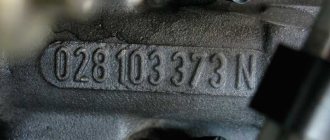
Where is the DTOZ installed?
Modern car enthusiasts do not know where the coolant temperature sensor is located. It can be found in the exhaust line of the cylinder head. The sensor body has a thread and it simply screws into the appropriate hole.
Depending on the design features of the car, the year of manufacture, the DTOZH may also be located near the thermostat housing or directly in it. This element is installed in such a way that it is in direct contact with antifreeze, antifreeze and other coolant options.
What affects the starting of a gasoline engine?
The operating principle of the engine has not changed since the construction of the first car. It is still necessary to have something to ignite and something to ignite the working mixture in the cylinders. Only the ways of ensuring this process have changed.
Let us list the main factors influencing the reliable start of the engine in winter.
Usually, difficult starting indicates a careless attitude towards technology in general.
As you can see, it’s difficult to single out the only reason why the car won’t start in the cold. But what to do if the car won’t start, but you need to drive? The best option is to use a taxi.