Methods for diagnosing an oxygen sensor
Experts advise checking the correct operation of the lambda probe every 10,000 km, even if there are no problems with the operation of the device.
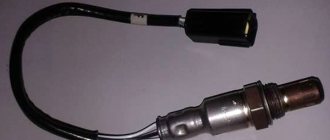
Diagnostics begins with checking the reliability of the connection between the terminal and the sensor and for the presence of mechanical damage. Next, unscrew the lambda probe from the manifold and inspect the protective casing. Small deposits are cleaned.
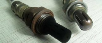
If, during a visual inspection, traces of soot, strong white, gray or shiny deposits were detected on the protective tube of the oxygen sensor, the lambda probe should be replaced
How to check a lambda probe with a multimeter (tester)
The sensor is checked for functionality using the following parameters:
- Heating circuit voltage;
- "Reference" voltage;
- Heater condition;
- Sensor signal.
Connection diagram to the lambda probe depending on its type
The presence of voltage in the heating circuit is determined with a multimeter or voltmeter in the following sequence:
- Without removing the connector from the sensor, turn on the ignition.
- The probes are connected to the heating circuit.
- The readings on the device must match the voltage on the battery - 12V.
“+” goes to the sensor from the battery through the fuse. In its absence, this circuit is called.
“—” comes from the control unit. If it is not detected, check the terminals of the lambda probe - ECU circuit.
The reference voltage measurements are carried out using the same devices. Sequencing:
- Turn on the ignition.
- Measure the voltage between the signal wire and ground.
- The device should show 0.45 V.
To check the heater, set the multimeter to ohmmeter mode. Diagnostic stages:
- Remove the connector from the device.
- Measure the resistance between the heater contacts.
- The readings on different oxygen pumps are different, but should not go beyond 2-10 ohms.
A voltmeter or multimeter is used to check the sensor signal. For this:
- They start the engine.
- Warm it up to operating temperature.
- The probes of the device are connected to the signal wire and the ground wire.
- Engine speed is increased to 3000 rpm.
- Monitor voltage measurements. Jumps should be observed in the range from 0.1 V to 0.9 V.
If during at least one of the checks the indicators differ from the norm, the sensor is faulty and needs to be replaced.
Video: checking the lambda probe with a tester
Checking with an oscilloscope
The main advantage of this lambda probe diagnostic over checking with a voltmeter and multimeter is the recording of the time between similar changes in the output voltage. It should not exceed 120 ms.
Sequence of actions:
- The probe of the device is connected to the signal wire.
- The engine is warmed up to operating temperature.
- Engine speed is increased to 2000-2600 rpm.
- Based on the oscilloscope readings, the performance of the oxygen sensor is determined.
Diagnostics with an oscilloscope gives the most complete picture of the operation of the lambda probe
Exceeding the time indicator or crossing the voltage limits of the lower 0.1 V and upper 0.9 V indicates a faulty oxygen sensor.
Video: diagnosing an oxygen sensor with an oscilloscope
Other verification methods
If the car has an on-board system, then the “CHECK ENGINE” signal, which generates a certain error, can be used to diagnose the condition of the lambda probe.
List of lambda probe errors
In order for the lambda probe to work for a long time and efficiently, it is necessary to fill the car only with high-quality fuel. Scheduled and timely diagnostics of the oxygen sensor will help to detect its malfunction in time. This measure can extend the life of not only the sensor itself, but also the catalyst.
Home → Device → Engine →
Engine diagnostics based on oxygen sensor readings
Before we talk about the design, operation and diagnostics of the lambda probe, let us turn to some features of the operation of the fuel system. The magazine's expert, Fedor Aleksandrovich Ryazanov, a diagnostician with extensive work experience, and the head of training courses for diagnosticians at , will help us with this. The modern motorist wants to own a powerful, but at the same time economical car. Environmentalists have a different requirement - a minimum content of harmful substances in car exhaust. And in these matters, the interests of motorists and environmentalists ultimately coincide. And that's why. It is known that when the engine does not burn all the fuel, fuel consumption increases, and the costs of operating the car also increase. The power of the engine (or internal combustion engine) under conditions of incomplete combustion of fuel inevitably drops, and the torque decreases. At the same time, the level of harmful substances in the vehicle exhaust increases. In this regard, one of the main tasks of the modern automotive industry is the most complete combustion of the fuel mixture in the engine. The combustion of the mixture is directly affected by its composition. The ideal situation is a stoichiometric fuel composition. In simpler terms, the proportion must be observed - 14.7 kg of air must account for 1 kg of fuel. It is this ratio that allows optimal use of both. The car owner receives more torque and, as a result, adequate acceleration of the car and uniform engine operation in all operating modes. Fuel consumption also drops, and the car stops polluting the environment. Deviations from the correct composition of the fuel mixture - rich and lean mixture. A rich fuel mixture is formed when there is little oxygen in the cylinders, but a lot of fuel, which, of course, due to the lack of oxygen, will not be able to burn completely. Consequently, a car running on a rich mixture will consume more fuel, and the excess of unburned fuel, in this case, will cool the combustion chamber, engine power will decrease, and unburned fuel will enter the atmosphere, polluting it. Another situation: the engine receives a lean fuel mixture. In this case, the fuel in the cylinders will not burn completely due to lack of fuel. In this case, you will also have to forget about the efficiency for which such engines were developed. After all, a lean mixture burns poorly, and this automatically leads to a drop in torque. The driver has to press the gas harder, which in turn leads to excessive fuel consumption. Thus, it is clear that from all aspects only the stoichiometry of the fuel mixture (proportion 14.7/1) is the most optimal engine operating mode. And, of course, a car that has just rolled off the assembly line usually fits within all the limits of this criterion. But the “factory” setting may differ from the ideal. Moreover, during the operation of the car, wear of some components inevitably occurs; the sensors responsible for tuning the fuel system may lose the accuracy of the settings. As a result, the composition of the fuel mixture moves further and further away from ideal values. In this case, a lambda probe is precisely what is needed; it records the amount of oxygen in the car’s exhaust. And if there is a large amount of oxygen in the exhaust, this “signals” that the fuel mixture is lean and, conversely, if there is no oxygen in the exhaust, this indicates that the mixture has become rich. And we have already found out that in both cases, engine power decreases, fuel consumption increases, and the environmental friendliness of the exhaust decreases. The task of the lambda probe is precisely to correct these deviations. Let's take this situation as an example: the injectors in the fuel system are clogged, their performance has decreased, and the mixture has become lean. The lambda probe records this fact, and the fuel system control unit reacts to this information and “adds” some fuel to the cylinders. This is how the resulting deviations are corrected, taking into account the readings of this sensor. Thus, the main purpose of the lambda probe is to compensate for deviations in the composition of the fuel mixture that inevitably arise during the operation of the vehicle. However, you need to understand that the lambda probe as such is not a panacea for all ills; it only allows you to return the composition of the fuel mixture to a state of stoichiometry. But this is not the elimination of defects, but only their compensation. Let's return to our injectors. If the injectors are dirty, the efficiency of gasoline atomization is impaired, the fuel is sprayed into large droplets, and they evaporate with difficulty. And the fuel supply system calculates the volume of fuel that is necessary to achieve a state of stoichiometry; for this, the readings of the air flow sensor are recorded. However, if gasoline is sprayed into the system in large drops, its vapors do not completely mix with the air, some of the vapors burn, and some of the gasoline droplets simply fly out into the exhaust pipe. The lambda probe interprets this situation as a lean mixture, and the fuel system sensor, which “does not see” individual drops of gasoline, adds fuel to bring the mixture to a state of stoichiometry. But in this case, fuel consumption increases sharply. Therefore, for the operation of a lambda probe, what is important is not the factor of how the system copes with bringing the mixture to stoichiometry, but the factor of what “cost” it manages to do this. Let's look at the oscillogram of the lambda probe. The sensor itself cannot distinguish the state of stoichiometry from the state of a rich fuel mixture, since in both cases there is no oxygen in the exhaust. If there is no oxygen in the fuel, the control unit (ECU - electronic control unit) slightly reduces the amount of fuel supplied to the cylinder. As a result, oxygen appears in the exhaust. And in this case, the lambda probe readings are below 0.4 V, which for the sensor is a sign that the fuel mixture is lean (LEARN). When the lambda probe readings are low (below 0.4 V), the control unit increases the fuel supply by several percent, the mixture becomes rich and the sensor readings reach a level above 0.6 V. The ECU perceives this as a sign that there is a rich mixture (RICH) in the fuel system. The fuel supply decreases, the lambda probe readings drop, the cycle repeats - the composition of the mixture begins to fluctuate. In response to changes in the composition of the mixture, the readings of the lambda probe change. The ECU understands such fluctuations as a normal phenomenon, indicating that the composition of the fuel mixture is in the stoichiometric zone. Let us also remember that a car catalyst necessarily contains zirconium; this metal is capable of accumulating oxygen. And in the lean mixture phase, oxygen is stored in the catalyst, and in the rich mixture phase it is consumed. As a result, at the exit of the fuel mixture, the catalyst burns out all its residues. At idle, such oscillations occur with a frequency of one oscillation in approximately one second. The time of such switching is another important indicator for the lambda probe. In our case (see oscillogram, Fig. 1) the switching time was 88 ms, while the norm is 120 ms.
If the switching lasts a long time, as in the case of our oscillogram (see oscillogram, Fig. 2) - 350 ms, and besides, this situation is repeated many times, the control unit will generate an error: “slow response of the lambda probe.”
The values at which this error appears are determined mainly by the software settings of the control unit. Thus, for diagnostics using a lambda probe, it is necessary to study the switching phases of the sensor. And if at least one switch from low to high reading appears on the oscillogram (maximum - 1V, minimum - 0V), this means that the lambda probe is working properly. A working sensor makes approximately one switch per second. Let us recall that in the operating algorithm of the control unit, a lean mixture is signaled by lambda probe readings below 0.4 V, and a rich mixture by values above 0.6 V. Therefore, the condition of the vehicle’s fuel system can also be assessed by the operation of the sensor. In our case (see oscillogram, Fig. 3), the control unit managed to compensate for all defects and output stoichiometry.
Let's return to the example of dirty injectors. When the mixture is lean, the lambda probe readings drop below 0.4V. The control unit adds fuel until the mixture becomes rich. Note that in this case the control unit “on its own” deviated from the parameters set by the manufacturer in its map. He records the amount of deviation in his memory as fuel trime. The maximum permissible fuel trim values for most modern cars are ±20-25%. A correction to “plus” means that the unit had to add fuel, a correction to “minus” means, on the contrary, to decrease it. Let’s say the malfunction is long-term: the control unit has already reached the fuel correction limit, the error code “Exceeding the fuel correction limits” lights up. By erasing the code, such a defect cannot be corrected, and the presence of this malfunction will lead to excessive fuel consumption. It is worth noting that already at 15% of the fuel correction problems are detected: the car hardly drives, but consumes a large amount of fuel. That is, it is important to remember that the fuel correction indicator and the operation of the lambda probe are a complex parameter; it indicates the presence of a defect, but does not indicate a specific cause that will have to be found and eliminated at a car service center. And a little about the structural features of the lambda probe. This sensor has a zirconium bulb, one side of which is placed in the exhaust gases. Zirconium is a unique material because oxygen can pass through it. The oxygen ion, “sticking” to the zirconium atoms, moves along them, and a voltage arises on the zirconium cap. And if everything goes as usual, then the diffusion of oxygen ions occurs evenly, and the voltage on the plates of the cone is 1V. If oxygen appears in the exhaust, diffusion is impossible and the voltage in this case is 0V. Instead of zirconium, titanium oxide can be used in lambda probes. The difference between a zirconium lambda probe and a titanium one is that the first one generates voltage, while the other one changes its resistance (from 0 to 5V), and it needs a circuit that converts the changing resistance into voltage. A layer of platinum on the cone on top of zirconium allows you to relieve stress from it, plays the role of a catalyst, and burns gasoline and unburned oxygen. Everything gets worse when using low-quality fuel, as well as fuel additives, which literally clog the platinum and zirconium layer, and the probe fails. However, in this case, if the probe is not physically damaged, a simple flush will return it to working condition. The “modern scourge” is the addition of anti-knock additives to fuel. Until recently, ferrocent was used as an additive, a dangerous substance that we dubbed “red death” for its red tint, as well as for its ability to quickly damage spark plugs, lambda probes and catalysts,” notes Fedor Aleksandrovich. The probe can “freeze” in a high or low position, that is, in either the rich or lean phase. And in this case, the sensor will reach the fuel trim limits and stop trying to equalize the mixture to stoichiometry. We begin diagnosing the condition of the fuel supply system by connecting the scanner to the car. The absence of the “Fuel trim limits exceeded” code does not mean that there are no defects in the fuel supply system. It is necessary to verify in the Data Stream that there are oscillations of the lambda probe (stoichiometry has been achieved), and also to estimate by the value of the fuel correction at what cost it was achieved. To summarize, we note once again that when checking the lambda probe, you need to pay attention to fluctuations in the sensor; if there are any, the sensor is working; if the lambda regulation system does not oscillate, this may indicate either a malfunction of the lambda probe or a lean or rich fuel mixture. That is, you first need to check the sensors themselves. To do this, you need to forcibly enrich or lean the mixture in order to obtain lambda oscillations and make sure that it is working properly. The lambda probes discussed above are called “jump probes”. Those. they indicate whether there is oxygen in the exhaust or not. But increasingly stringent environmental requirements have forced manufacturers to develop sensors that can not only work on the “Yes-No” principle, but also determine the percentage of oxygen in the exhaust. Such sensors are called “broadband oxygen sensors”. The principles of their operation and the features of diagnosing a car based on the readings of broadband lambda probes will be discussed in the following publications. OPINION Maxim Pastukhov, technical specialist: “Practice shows that the main reasons for failure of lambda probes are: 1. Contamination of the lambda probe with fuel combustion products. In fact, these are additives that are used to increase the octane number of gasoline, eliminate detonation, or for other purposes. This is also affected by the degree of fuel purification. Additives, sulfur and paraffins “clog” the conductive layer of the lambda probe, and it “goes blind”. The control unit puts the engine into emergency mode, and we see the “Check Engine” icon on the dashboard. By the way, spark plugs, valves, catalyst and other engine components also suffer from the things described above. It makes sense to take a comprehensive approach to repairs if the lambda probe fails. 2. An aggressive mixture that is sprinkled on our roads. It corrodes the insulation of the wires and the wires themselves. To protect against this, we use double insulation of the wires, and also hide the place where the wires and the sensor are welded inside the lambda probe.” 04/09/2014
Excess air coefficient λ
Before disassembling the design of the oxygen sensor and the principle of its operation, it is necessary to decide on such an important parameter as the excess air ratio of the air-fuel mixture: what it is, what it affects and why the sensor measures it.
In the theory of internal combustion engines, there is such a thing as the stoichiometric ratio - this is the ideal proportion of air and fuel at which complete combustion of the fuel occurs in the combustion chamber of the engine cylinder. This is a very important parameter on the basis of which fuel supply and engine operating modes are calculated. It is equal to 14.7 kg of air to 1 kg of fuel (14.7:1). Naturally, such an amount of the air-fuel mixture does not enter the cylinder at one point in time, this is just a proportion that is recalculated for real conditions.
Dependence of power (P) and fuel consumption (Q) on the excess air ratio
Excess air factor (λ)
- this is the ratio of the actual amount of air entering the engine to the theoretically necessary (stoichiometric) for complete combustion of the fuel. In simple terms, this is “how much more (less) air entered the cylinder than it should have.”
Depending on the value of λ, three types of air-fuel mixture are distinguished:
- λ = 1 – stoichiometric mixture;
- λ < 1 – “rich” mixture (excess – fuel; deficiency – air);
- λ > 1 – “lean” mixture (excess – air; deficiency – fuel).
Modern engines can operate on all three types of mixture, depending on the current tasks (fuel economy, intense acceleration, reducing the concentration of harmful substances in exhaust gases). From the point of view of optimal engine power values, the lambda coefficient should have a value of about 0.9 (“rich” mixture), the minimum fuel consumption will correspond to a stoichiometric mixture (λ = 1). The best results for exhaust gas purification will also be observed at λ = 1, since effective operation occurs with a stoichiometric composition of the air-fuel mixture.
What types of sensors are there?
The sensors are available in one-, two-, three- and four-wire versions. The first two versions are now rare. Their disadvantage is the need to install the sensor in close proximity to the cylinder block, because they were put into operation at temperatures above 300°C. This caused certain delays in the feedback from the control unit and sensor. The latest four-wire models are completely free of all these shortcomings.
Sensors are available with or without heating
. Heated sensors are equipped with a heating element. This version has a longer service life.
Thus, a faulty or inoperative sensor leads to a loss of engine power, idle failures, increased fuel consumption, carbon deposits due to incomplete combustion of the mixture, increased wear on the cylinders, and increased emissions of harmful substances. This is what the lambda probe affects, and this is not the whole list of consequences of its incorrect operation. The consequences are by no means harmless.
Wideband Sensor Duty Cycle
The working area of a broadband lambda probe is conventionally divided into 4 parts. This is convenient for understanding the operating principle of the unit during diagnostics, when a system error appears on the dashboard.
- Chamber of the ion electrolysis pump - A.
- Sensitive element or Nernst element - V.
- Electrical circuit - S.
- ECU - D.
Exhaust gases, passing through the system pipe, penetrate into the diffusion gap, where the afterburning process occurs. After afterburning, either an excess or a lack of oxygen is formed in the chamber. The time of catalytic combustion of solid particles in the chamber takes 0.01 seconds, but since the afterburning process occurs only when the gas is heated at high temperatures (from 200–300 degrees Celsius), the chamber is heated through the heater element.
After the fuel exhaust burns out in the block, the Nernst sensitive element compares the resulting air composition with the reference one and transmits information to the engine ECU in one of three options:
- lack of oxygen (lambda “minus”), the mixture is lean;
- excess (lambda “plus”), enriched mixture;
- stoichiometry (lambda = 1) is a balanced parameter.
Based on the indicators, the ECU sends a pulse to the ion pump unit. Depending on the primary data, the control unit transmits one of three commands.
- If there is an excess of oxygen, a positive current is formed, the mixture is lean, it is necessary to conduct excess oxygen into the exhaust pipe.
- If the mixture is enriched, it is necessary to pump oxygen from the exhaust system manifold into the chamber and generate a negative current.
- At stoichiometry, the ECU does not give a signal.
During the formation of a positive or negative current in the ion pump block, an indicator of the qualitative composition of the exhaust mixture is formed. The ECU reads the current parameter on the sides of the pump and generates signals to adjust the fuel supply to the injection system.
After the introduction of wide-bandwidth sensors into the outlet manifold system, the diagnostic process was significantly simplified and there was no need to use gas analyzers. But not everything is so simple in the operation of modern sensors.
Causes of malfunction
Why might this mechanism fail? The first reason is natural wear and tear. If the car's mileage is more than 50 thousand kilometers, the service life of the mechanism may come to an end. But the sensor also breaks down for other reasons:
- If the wires that go to the sensor break. In this case, the signal simply will not be sent to the ECU.
- In case of mechanical damage. Many sensors are installed near the bottom. If the vehicle drives through a deep obstacle, the measuring element may be damaged. The slightest deformation destroys the galvanic element of the broadband oxygen sensor.
- When the sensor overheats. This can happen due to problems with the car's fuel system. Usually this is an incorrect ignition angle or incorrect engine tuning (for example, the wrong ECU firmware during chip tuning).
- When the sensing element is dirty. If the platinum-coated top layer becomes coked, the ions will not be picked up by the broadband sensor. What could it be? Typically, contamination occurs due to oil entering the combustion chamber. this soot then envelops the walls of the exhaust manifold, as well as the sensor tip. Pollution can also occur due to the use of low-quality gasoline, which contains a lot of lead.
- When the housing is depressurized. This happens rarely, but this malfunction should not be ruled out.
- If antifreeze gets into the engine cylinders. This is due to a blown head gasket. As a result, the gases acquire a characteristic white color. In addition, the oxygen concentration in the exhaust also changes. In simple words, the sensor begins to “go crazy.” The ECU is preparing the wrong mixture.
How it works?
The algorithm of action of this element is based on maintaining a certain voltage. It is 0.45 V. This is a stable indicator between the two electrodes of the sensor.
As the O2 concentration decreases, the voltage between the ceramic element increases. this indicates the presence of an enriched mixture. This signal is instantly sent to the electronic control unit. The latter, based on these signals, creates a current of a certain strength on the actuators (including the injector). That, in turn, injects more (or less, depending on the readings) gasoline into the chamber. If the mixture is lean, the sensor signals this to the ECU in the same way.
Design parameters of a wide-band lambda probe
The location of the sensor is on the exhaust manifold pipe in front of the catalytic converter unit. For more precise control over the composition of the exhaust gas and the operation of the catalyst, a second oxygen tank can be installed after the converter unit. Wide-band element design.
- Electrolysis (ion) pump chamber.
- Reference electrodes (platinum coated).
- Heating plate.
- Reference pass.
- Ceramic block (ZrO2).
- Diffusion gap.
- Measuring (reference) chamber.
- Platinum electrodes of the measuring chamber.
- Electrodes of the ion electrolysis chamber (pump).
Wideband designs produce a lambda value (ideal or stoichiometric fuel assembly) as a hyperbola as the amperage increases. Zirconium and titanium meters are deprived of the ability to accurately monitor changes in the parameters of the fuel mixture due to the design feature; the only indicator that is available to such sensors is to transmit to the ECU a signal about the state of the fuel assembly in the following values: “Enriched”, “Lean”.
About the operation of the sensor
The lambda probe is a non-separable design and is designed for a range of up to eighty thousand kilometers. True, this figure can decrease significantly if operating rules are violated. Among them it is worth noting:
- use of leaded gasoline or other types of fuel not provided by the manufacturer;
- sensor overheating;
- repeated unsuccessful engine starts;
- contact of the sensor housing with automotive operating fluids or detergents;
- short to ground, as well as poor contact of the output circuit.
There may be other reasons that cause sensor failure, but those already given are enough to understand that this is a fragile product and requires careful handling during operation. You can fully check the sensor with the required degree of reliability using an oscilloscope. However, the results of the sensor’s operation are visible to the naked eye based on a number of signs:
- increased fuel consumption;
- increase in the content of carbon monoxide in the composition of VG;
- deterioration of vehicle dynamics;
- unstable motor operation.
There may be several reasons for sensor failures, but regardless of them, repairs are not provided for it, only replacement.
The lambda probe in modern cars controls the amount of oxygen in the combustion engine. It also provides data to the engine control controller in order to change the composition of the fuel assembly for complete combustion of the mixture and ensure the necessary operating conditions for the converter.
What else is worth reading
Why do you need a knock sensor?
Lean fuel mixture
Operating principle of a robotic gearbox
Composition of gasoline
Signs of malfunction of the lambda sensor
Damage to the lambda zone is a fairly common malfunction. This failure may be associated both with the design of the sensor and with the conditions in which this element operates. In theory, the probe should withstand 150 thousand kilometers or even more, but in reality it is often different. After all, lambdazone is located in the exhaust system, where it is constantly exposed to high temperatures and chemicals.
The quality of the fuel used also has a big impact on the life of the sensor. Just one refueling with leaded or low-quality fuel can lead to irreversible damage to the lambda probe. Unburnt impurity is deposited on the sensor and blocks its operation. Therefore, the car should be refueled only with high-quality high-octane fuel at trusted gas stations.
On the other hand, the sensor housing extends beyond the exhaust system, where it is exposed to constant contact with water and dirt. It happens that due to a sudden jump or jerk in the car, for example, due to hitting an obstacle, tension occurs in the sensor wires that go to the engine controller. As a result, the cable may simply wear out or even break, which will also require you to replace the sensor. Therefore, it is not surprising that the sensor, like most mechanical devices in a car, wears out over time and unexpectedly fails.
In turn, the most common signs of lambdazone malfunction are:
- A sharp increase in fuel consumption, up to 50%;
- Loss of engine power;
- Spontaneous change in engine speed;
- Unstable motor operation, periodic pops and jolts;
- It takes a long time to respond to pressing the gas pedal;
- Black smoke from the exhaust pipe;
- Increased emissions of carbon oxides and hydrocarbons from exhaust gases;
- The Check Engine light comes on;
- After clearing the fault code from the engine ECU, the error returns again.
In addition to the above signs of lambdazone malfunction, incorrect operation of the probe, as well as the engine itself, may be indicated by colored deposits on its surface, for example:
- Black and greasy deposits on the probe indicate excessive oil consumption by the engine.
- Green and hard deposit – coolant is entering the combustion chamber.
- A dark brown color indicates the air/fuel mixture is too rich.
- A reddish or whitish tint indicates the use of undesirable fuel additives in the fuel used.
If you do nothing
First of all, the motorist himself will suffer, as fuel consumption will increase, and the exhaust gases will have a toxic smell with strong hues from the pipe. In the case of modern cars with a lot of electronics that know how to check the health of the oxygen sensor, the lock is activated. In such a situation, any movement by car will become impossible. But the worst option is depressurization. The car will not move at all or will have difficulty starting. This can lead to complete engine failure. In the event of depressurization, all gases will enter the air intake channel instead of the exhaust pipe. When engine braking is performed, the probe will detect toxicity and give negative signals. This will completely damage the injection system. The main sign of depressurization is loss of engine power. This can be felt while driving at speed. Also, knocking and popping noises and a smell will be heard from under the hood. Previously, motorists needed to know how to adjust the carburetor. Now nothing has changed - you need to remember how to check the oxygen sensor (VAZ-2112 is no exception).
Purpose of oxygen sensors
Location of oxygen sensors in the exhaust system
As a standard, modern cars use two oxygen sensors (for an in-line engine). One before the catalyst (upper lambda probe), and the second after it (lower lambda probe). There are no differences in the design of the upper and lower sensors; they may be the same, but perform different functions.
The upstream or front oxygen sensor detects the amount of remaining oxygen in the exhaust gases. Based on the signal from this sensor, the engine control unit “understands” what type of air-fuel mixture the engine is running on (stoichiometric, rich or lean). Depending on the oxygen sensor readings and the required operating mode, the ECU adjusts the amount of fuel supplied to the cylinders. As a rule, the fuel supply is adjusted towards the stoichiometric mixture. It should be noted that when the engine warms up, signals from the sensor are ignored by the engine ECU until it reaches operating temperature. The lower or rear lambda probe is used to further adjust the mixture composition and monitor the proper operation of the catalytic converter.
Oxygen sensor: purpose, types, device, photo, principle of operation
Common causes of lambda probe malfunctions and ways to eliminate them
Oxygen content sensors in the air-fuel mixture fail over time, which can be determined by unstable engine operation and increased fuel consumption. The reasons for the malfunction of the lambda are refueling with low quality fuel, problems with the fuel preparation and supply system, or contact with special fluids on the sensor. The problem is manifested by the following symptoms:
- a sharp increase in speed to maximum values and instantaneous shutdown of the engine;
- deterioration in the quality of the mixture supplied to the cylinders, reduction in combustion efficiency;
- fluctuations in idle speed;
- a significant decrease in power with increasing speed;
- malfunctions of electronic units due to delays in the supply of signals from the sensor;
- the car moves jerkily;
- the appearance in the engine compartment of sounds that are uncharacteristic during normal engine operation;
- late injection when the pedal is pressed.
To restore the functionality of the electronics and injection system, you will need to replace or properly clean the lambda probe. When cleaning, you need to remove the ceramic tip and remove dirt using chemicals.
Electronic lambda probe test
You can find out about the condition of the lambda probe by checking it on professional equipment. An electronic oscilloscope is used for this. Some experts determine the performance of the oxygen sensor using a multimeter, however, it can only state or deny the fact of its failure.
The device is checked during full engine operation, since at rest the sensor will not be able to fully convey a picture of its performance. In case of even a slight deviation from the norm, it is recommended to replace the lambda probe.
Replacing the lambda probe
In most cases, a part such as a lambda probe cannot be repaired, as evidenced by statements about the impossibility of repair from many automobile manufacturers. However, the inflated cost of such a unit from official dealers discourages anyone from purchasing it. The optimal way out of this situation could be a universal sensor, which costs much less than its native analogue and is suitable for almost all car brands. Also, as an alternative, you can purchase a used sensor, but with a warranty period, or a completely exhaust manifold with a lambda probe installed in it.
However, there are cases when the lambda probe operates with a certain error due to severe contamination as a result of combustion products deposited on it. In order to make sure that this is really the case, the sensor must be checked by specialists. After the lambda probe has been checked and its full functionality has been confirmed, it must be removed, cleaned and reinstalled.
In order to dismantle the oxygen level sensor, it is necessary to warm its surface to 50 degrees. After removal, the protective cap is removed from it and only after that you can start cleaning. It is recommended to use phosphoric acid as a highly effective cleaning agent, which can easily cope with even the most stubborn flammable deposits. At the end of the soaking procedure, the lambda probe is rinsed in clean water, thoroughly dried and installed in place. At the same time, do not forget about lubricating the threads with a special sealant, which will ensure complete tightness.
The structure of a car is very complex, so it needs constant maintenance and timely preventative maintenance. Therefore, if there is a suspicion that the lambda probe is faulty, it is necessary to immediately diagnose its performance and, if the fact of failure is confirmed, replace the lambda probe. Thus, all the most important functions of the vehicle will be maintained at the same level, which will guarantee the absence of further problems with the engine and other important elements of the car.
Question answer
Q: What is the difference between special and universal sensors? A: These sensors have different installation methods. Special sensors already have a contact connector included and are ready for installation. Universal sensors may not come with a connector, so you need to use the connector of the old sensor.
Q: What happens if the oxygen sensor fails? O: If the oxygen sensor fails, the ECU will not receive a signal about the ratio of fuel and air in the mixture, so it will set the amount of fuel supply arbitrarily. This can lead to less efficient use of fuel and, as a result, increased fuel consumption. This can also cause a decrease in the efficiency of the catalyst and an increase in the toxicity of emissions.
Q: How often should the oxygen sensor be replaced? A: DENSO recommends replacing the sensor according to the vehicle manufacturer's instructions. However, you should check the performance of the oxygen sensor every time your vehicle is serviced. For engines with a long service life or where there are signs of increased oil consumption, the intervals between sensor replacements should be reduced.
Range of oxygen sensors
• 412 catalog numbers cover 5,394 applications, corresponding to 68% of the European vehicle fleet. • Heated and non-heated oxygen sensors (switchable type), air-fuel ratio sensors (linear type), lean mixture sensors and titanium sensors; two types: universal and special. • Regulating sensors (installed in front of the catalyst) and diagnostic sensors (installed after the catalyst). • Laser welding and multi-step inspection ensure that all features are exactly as original equipment specifications, ensuring long-term performance and reliability.
DENSO has solved the fuel quality problem!
Did you know that poor quality or contaminated fuel can shorten the life and performance of your oxygen sensor? Fuel can be contaminated by engine oil additives, gasoline additives, sealants on engine parts, and oil deposits from desulfurization.
When heated above 700 °C, contaminated fuel releases vapors harmful to the sensor. They affect sensor performance by forming deposits or destroying sensor electrodes, which is a common cause of sensor failure. DENSO offers a solution to this problem: the ceramic element of DENSO sensors is coated with a unique protective layer of aluminum oxide, which protects the sensor from poor quality fuel, extending its life and maintaining its performance at the required level.
Q: Why do some cars have two oxygen sensors? O: Many modern cars, in addition to the oxygen sensor located in front of the catalyst, are equipped with a second sensor installed after it. The first sensor is the main one and helps the electronic control unit regulate the composition of the air-fuel mixture. A second sensor, installed after the catalyst, monitors the efficiency of the catalyst by measuring the oxygen content of the exhaust gases at the outlet. If all the oxygen is absorbed by the chemical reaction occurring between oxygen and harmful substances, the sensor produces a high voltage signal. This means that the catalyst is working properly. As the catalytic converter wears out, a certain amount of harmful gases and oxygen ceases to participate in the reaction and leaves it unchanged, which is reflected in the voltage signal. When the signals become the same, this will indicate catalyst failure.
Q: Why does the air-fuel mixture need to be constantly adjusted? A: The air-fuel ratio is critical because it affects the efficiency of the catalytic converter, which reduces carbon monoxide (CO), unburned hydrocarbons (CH) and nitrogen oxide (NOx) in the exhaust gases. For its effective operation, it is necessary to have a certain amount of oxygen in the exhaust gases. The oxygen sensor helps the ECU determine the exact air-fuel ratio of the mixture entering the engine by providing the ECU with a rapidly varying voltage signal that changes according to the oxygen content of the mixture: too high (lean mixture) or too low (rich mixture).
The ECU reacts to the signal and changes the composition of the air-fuel mixture entering the engine. When the mixture is too rich, fuel injection is reduced. When the mixture is too lean, it increases. The optimal air-fuel ratio ensures complete combustion of the fuel and uses almost all the oxygen from the air. The remaining oxygen enters into a chemical reaction with toxic gases, as a result of which harmless gases come out of the neutralizer.
The design and operating principle of a modern torque converter: description, photo
McPherson suspension: device, description, purpose, photo
Knock sensor: description, types, device, principle of operation
Variator: description, photo, principle of operation, device, types
Probe diagnostics with a multimeter
If the sensor visually shows no signs of malfunction, there are no deposits, the functionality of the circuit is checked. Bosch wideband sensors, which are most often installed on cars, have six connection wires:
- Red - signal plus;
- Yellow—support plus;
- Black—reference minus;
- White – heater minus;
- Gray - heater plus;
- Green is a signal minus.
To check the functionality, a certain wire will be connected to the multimeter probe. Checking the integrity of the electrical circuit of a unit is divided into four stages.
- Diagnostics of voltage in the heating element.
- Voltages in the probe reference block (reference voltage).
- Heating element resistance (checking condition).
- Signal.
To check the voltage in the heating element, turn on the ignition, the probe remains in the connector. The multimeter probes are connected to the heating wires (white, gray). If the circuit is working, the voltage numbers on the tester screen will match the on-board network voltage - 12 V.
The voltage in the wiring of the support block is checked in the same way. The probes are installed on the signal wire and ground (yellow, black), the working wiring will display a reading of 0.45 V on the tester screen.
Wide-band probe designs can only operate after heating. The performance of the heating part of the sensor is checked by the resistance of the element. The sensor is removed from the connector and the resistance between the heater contacts is checked. Each probe has individual resistance parameters, but in any case they are in the range of 2–10 ohms.
The higher the oxygen concentration in the exhaust gases, the lower the conductivity and the lower the emf.
The voltage at the sensor signal pin drops. With a stoichiometric mixture composition, the average voltage at the signal electrode is approximately 0.5 V. Therefore, many manufacturers support this voltage from the engine ECU as a reference. The oxygen sensor starts working when it reaches a temperature of 300 - 400 degrees.
Before the sensor warms up and starts operating, the engine operation is controlled using an open-loop control circuit, i.e. without feedback - according to the algorithm embedded in the ECU. Some manufacturers do not use a reference voltage, but maintain zero voltage at the input to the ECU. After the engine warms up, the oxygen sensor readings begin to change and the engine control switches to closed-loop control mode with feedback. If, after warming up and operating the engine in various modes, the values at the signal output of the sensor have not changed, the self-diagnosis system of the engine ECU should detect a malfunction of the oxygen sensor.
To warm up the oxygen sensor faster, some manufacturers place it directly on the exhaust manifold; the sensor quickly enters the operating temperature mode, but at the same time, it is subsequently used at elevated temperatures and fails faster. The heating element built into the sensor helps reduce the warm-up time. The resistance of the heating element is 3 - 15 Ohms. The voltage on the warm-up winding is 12 V. In 10 seconds at idle, a working sensor makes 4 - 6 switches. At higher engine speeds, the number of shifts increases with proper engine adjustment. The appearance of the oxygen sensor is shown in Fig. 3. Oscillogram of a working oxygen sensor - in Fig. 4.
The titanium (TIO2) oxygen sensor works on a different principle - it changes conductivity depending on the oxygen content in the exhaust gases. The titanium sensor changes resistance from 1 Kom to 100 Kom when the oxygen content in the exhaust gases changes. “Lean” mixture: high resistance and low voltage. Rich mixture: low resistance and high voltage.
The reference voltage is usually 1 V. The voltage change on the signal wire is from 0.6 to 4.8 V. The resistance of the heating element is from 7 to 40 Ohms.
In Fig. Figure 5 shows the signal switching characteristics depending on the composition of the mixture. In Fig. Figure 6 shows an oscillogram in mode XX of a working sensor.
With a rich mixture, the resistance of the titanium element decreases, the current increases and the voltage on the signal wire increases.
Used on engines from NISSAN, OPEL, JEEP. To maintain high temperature dependence and operational stability, a heater is built into the sensor.
The lean ultra-lean sensor (LAF) is used to analyze mixture ratios in the range from 12:1 to 23:1, because... Conventional sensors do not work accurately in this range. The ZrO2 oxygen sensor works by moving oxygen ions in a solid electrolyte at different oxygen contents in the engine exhaust gases and in the air. A potential difference arises, which is analyzed by the engine ECU. The LAF sensor consists of two conventional zirconium sensors, but the overall design and operating principle is different and is as follows.
The outer side of the sensitive element of sensor 1 is located in the exhaust manifold and comes into contact with the exhaust gases (pin A). The inner side of the sensing element of sensor 1 is located in an insulated diffusion chamber (pin B). The contact on the outer side of sensor 1 is connected to the ECU. A voltage is generated on it, reflecting the difference in oxygen concentrations in the exhaust gases and in the diffusion chamber. The diffusion chamber does not come into contact with the atmosphere.
The internal part of the sensitive element of sensor 2 is located in the diffusion chamber (pin C), and the outer part is in the atmosphere (pin This is the pumping part. The movement of oxygen ions is a reversible process, i.e. the movement of oxygen ions between the electrodes creates a potential difference, and “application "voltage causes the movement of oxygen ions. A reference voltage of 2.7 V relative to ground is applied to the sensitive elements - the inside of sensor 1 and the inside of sensor 2. By creating a voltage on the control element of the outside of sensor 2 (D), the ECU can create conditions for the movement of oxygen ions into or out of the diffusion chamber.Voltage changes are made in such a way as to maintain the output voltage at pin A equal to 0.45 V, i.e. the voltage at pin D can be positive ("lean" mixture) or negative ("rich" mixture) Voltage range is approximately 1.5 V.
The lean air mixture sensor (LAF) is used to analyze the mixture composition in the range up to 23:1. A conventional oxygen sensor cannot accurately determine how lean the mixture is (TOYOTA, HONDA). Lean mixture sensor device: a constant voltage is applied to the zirconium sensing element, causing electric current to flow through it. The amount of current flowing will depend on the difference in oxygen concentrations at the electrodes. To create a constant current in the sensor, an additional diffusion layer is used. If the mixture is “rich,” then no current is generated in the sensor. If “poor”, the amount of generated current increases. To determine the degree of leanness of the mixture, the ECU changes the voltage at the sensor and “analyzes” the current increment, i.e. As the mixture becomes “leaner,” the current increases.
With an “enriched” mixture, the sensor operates like a regular zirconium sensor, i.e. generates a voltage of more than 0.5 V, and with a “lean” mixture it works as a current source and, to increase the sensitivity of the sensor, the ECU supplies voltage to it.
Wide Range Air/Fuel Sensor is used to analyze mixture composition in the range up to 23:1 (TOYOTA, LEXUS). The output signal of the sensor corresponds to the composition of the mixture over the entire range of its changes (Fig. 9).
With a constantly applied voltage, the current changes as the composition of the mixture changes. The operating temperature of such a sensor is higher, so high-power heaters with a heating current of up to 6 A are used. The resistance of the heating element is 0.8 - 1.5 Ohms. The pulse heating method is used.
LOCATION: In the exhaust manifold, before or after the exhaust gas converter.
FAULTS: The oxygen sensor is a replaceable element and lasts 80 - 150 thousand.
km, but can fail within 100 km or last 200 thousand km. Afraid of blows; use of leaded gasoline in the engine; gasoline with a high content of anti-knock agents; entry into the exhaust system of increased concentrations of unburned hydrocarbons: motor oil, unburned gasoline or various fuel additives.
A malfunction of a zirconium or titanium sensor can manifest itself in the following form: long warm-up, during which the voltage on the signal wire does not change; After the sensor warms up, the voltage on the signal wire hangs around average values or changes slowly within small limits.
CHECKING METHOD: Oxygen sensors can be single-wire - a signal wire (usually black) goes to the engine ECU, ground goes through the metal of the exhaust system; three wire - warm-up winding (two white wires), signal wire (usually black), ground through the metal of the exhaust system; four-wire - warm-up winding (two white wires), signal wire (usually black), ground (usually gray wire).
A normally operating sensor (if all engine systems are in good working order and located in front of the converter) makes 3 to 5 distinct “switchings” in 10 seconds. As the engine speed increases, the number of “switchings” increases.
You can check for a lean mixture by disconnecting the injector connector. A check for richness of the mixture can be carried out by turning off the vacuum pipe of the fuel pressure regulator or injecting a small amount of an aerosol engine quick start agent containing volatile ether compounds into the intake manifold. In this case, the voltage at the signal pin should change according to the rules given when describing the principles of operation of an oxygen sensor of this type. Oxygen sensors located after the congestion neutralizer are designed to check the efficiency of the neutralizer itself. If the signals from the oxygen sensors before and after the converter practically coincide, then the converter does not perform its functions. The signal from the oxygen sensor after a working neutralizer usually represents minor fluctuations in the area of the reference voltage.
REPAIR: Cannot be repaired.
Types of lambda probes
Modern cars are equipped with the following sensors:
- Zirconium;
- Titanium;
- Broadband.
Zirconium
One of the most common models. Created on the basis of zirconium dioxide (ZrO2).
The zirconium oxygen sensor operates on the principle of a galvanic cell with a solid electrolyte in the form of zirconium dioxide (ZrO2) ceramics.
The ceramic tip with zirconium dioxide is covered on both sides with protective shields made of conductive porous platinum electrodes. The properties of an electrolyte that allows oxygen ions to pass through appear when ZrO2 is heated above 350°C. The lambda probe will not work until it reaches the required temperature. Fast heating is achieved by a heating element with a ceramic insulator built into the body.
Exhaust gases enter the outer part of the tip through special gaps in the protective casing. Atmospheric air enters the sensor through a hole in the housing or a porous waterproof sealing cap (cuff) of the wires.
The potential difference is formed due to the movement of oxygen ions through the electrolyte between the outer and inner platinum electrodes. The voltage generated at the electrodes is inversely proportional to the amount of O2 in the exhaust system.
The voltage that is generated across the two electrodes is inversely proportional to the amount of oxygen
Based on the signal coming from the sensor, the control unit regulates the composition of the fuel assembly, trying to bring it closer to stoichiometric. The voltage coming from the lambda probe changes several times every second. This makes it possible to regulate the composition of the fuel mixture regardless of the operating mode of the internal combustion engine.
Based on the number of wires, several types of zirconium devices can be distinguished:
- In a single-wire sensor, there is a single signal wire. Ground contact is made through the housing.
- The two-wire device is equipped with signal and ground wires.
- Three- and four-wire sensors are equipped with a heating system, control and grounding wires to it.
Zirconium lambda probes, in turn, are divided into one-, two-, three- and four-wire sensors
Titanium
Visually similar to zirconium. The sensor's sensitive element is made of titanium dioxide. Depending on the amount of oxygen in the exhaust gases, the volumetric resistance of the sensor changes abruptly: from 1 kOhm with a rich mixture to more than 20 kOhm with a lean mixture. Accordingly, the conductivity of the element changes, which the sensor signals to the control unit. The operating temperature of the titanium sensor is 700°C, so the presence of a heating element is mandatory. There is no reference air.
Due to its complex design, high cost and fastidiousness to temperature changes, the sensor is not widely used.
In addition to zirconium, there are also oxygen sensors based on titanium dioxide (TiO2)
Broadband
Structurally differs from the previous ones in 2 chambers (cells):
- Measuring;
- Pumping room.
In the measurement chamber, using an electronic voltage modulation circuit, the gas composition corresponding to λ=1 is maintained. The pump cell, when the engine is running on a lean mixture, removes excess oxygen from the diffusion gap into the atmosphere; when the mixture is rich, it replenishes the diffusion hole with the missing oxygen ions from the outside world. The direction of the current to move oxygen in different directions changes, and its magnitude is proportional to the amount of O2. It is the current value that serves as the exhaust gas detector λ.
The temperature required for operation (at least 600°C) is achieved through the operation of the heating element in the sensor.
Wideband oxygen sensors detect lambda from 0.7 to 1.6
What is important and necessary to know when replacing a lambda probe
When installing a new lambda probe, consider the following:
- When removing and installing the oxygen sensor, use only special tools designed for this purpose. Special tools for removing sensors are available in sets, and there is also a separate lambda probe remover. Using it will greatly simplify the removal and installation of the sensor.
- Check the threads in the exhaust system for damage.
- Use only the supplied lubricant or lubricant specifically designed for lambda sensors.
- Avoid contact of the probe measuring element with water, oil, grease, cleaning agents and rust removers.
- Observe the appropriate tightening torques
specified by the lambda sensor or vehicle manufacturer. - When laying the connection cable, be careful that it does not come into contact with hot or moving objects or pass through sharp edges.
- Route the new lambda sensor cable according to the pattern of the originally installed sensor as far as possible.
- Do not lay wires under tension. Make sure that the connecting cable has enough flexibility before being pulled too tight so that it does not become detached from the exhaust system due to vibration and movement.
- Do not use any metal-based additives or fuels containing lead.
- Never use a lambda sensor that has fallen to the ground or is damaged.
Operating principle
Oxygen contains negatively charged ions. They are assembled on platinum electrodes and when the desired sensor temperature is reached (about 400 degrees Celsius), a potential difference (voltage) is created.
If the mixture is too lean, then the volume of oxygen in the gases will be high, and vice versa, if the mixture is rich, then there will be little oxygen.
In the first case, the voltage is 0.2-0.3 Volts, and in the second - 0.7-0.9 Volts.
The motor control system maintains a voltage level of about 0.4-0.6 Volts, that is, the lambda level is 1.0.
During movement, the operating modes of the motor change, which helps to adjust the voltage parameter in both directions. In this case, a narrowband sensor can only capture those parameters that are above zero.
The lambda probe, which is installed after the catalyst, has the same principle of operation.
After treating the gases with a catalyst, the oxygen level remains unchanged. This, in turn, allows you to maintain an optimal potential difference within 0.4-0.6 Volts.
Zirconium lambda probe
(Checking and replacing the lambda probe on Kia Ceed)
Note: this article is for general information and applies to any make of car with a zirconium lambda probe
There is a widespread belief that the lambda probe is a sensor for the presence of oxygen in the exhaust gases. This leads to a misunderstanding of the sensor's operation and, in some cases, leads to errors in diagnosis and repair.
There is a widespread belief that the lambda probe is a sensor for the presence of oxygen in the exhaust gases. This leads to a misunderstanding of the sensor's operation and, in some cases, leads to errors in diagnosis and repair.
Let's take a closer look at the operation of the engine control system and conduct some experiments to find out the details of the sensor's operation.
For complete combustion of 1 kg of gasoline, approximately 14.7 kg of air is required. This mixture composition is called “stoichiometric”. Complete combustion of fuel is accompanied by the formation of carbon dioxide (CO2) and water vapor (H2O). The ratio of the stoichiometric composition of the mixture to the real one is usually denoted by the letter - λ (Lambda). If λ< 1 (lack of air), the mixture is rich. If λ > 1 lean mixture. During the combustion of a stoichiometric mixture, the exhaust gases of a real engine also contain a small amount of toxic substances (CO, OH, NOx) and oxygen (O2). The combustion of a stoichiometric mixture ensures the lowest content of toxic substances in the exhaust gases, especially when working with a catalyst, optimal efficiency and engine power. In the presence of a catalyst, toxic substances interact with oxygen and are converted into non-toxic ones (CO2, H2O, N2).
If more gasoline is supplied to the cylinder than is required for complete combustion of the incoming air, then the mixture will be rich (λ < 1). In the exhaust gases, as the mixture becomes richer, the content of carbon monoxide (CO) will increase, and CO2 and H2O will decrease. When running on a rich mixture, there is almost no O2 in the exhaust. The combustion temperature is low and nitrogen oxides are practically not formed. A slight enrichment of the mixture leads to increased engine power, but a loss of efficiency. Strong enrichment leads to a loss of both power and efficiency.
When the engine is running on a lean mixture (λ > 1), when less gasoline is supplied than is needed for complete combustion of the incoming air, a significant amount of oxygen (O2) will be present in the exhaust gases. As the mixture becomes leaner, the concentration of oxygen will increase, and the concentration of carbon dioxide and water vapor will decrease. Almost no carbon monoxide (CO) is produced in the exhaust. Depending on the degree of leanness of the mixture, the exhaust gases may contain toxic NOx and CH. Slight leaning improves engine efficiency, but reduces power. Severe depletion leads to loss of both power and efficiency.
A sensor capable of measuring the composition of the mixture is called a lambda probe. The most common zirconium sensors are also called oxygen sensors. When the engine is running on a lean mixture, and with a significant oxygen content in the exhaust gases, the sensor signal will have a low level - the voltage will be in the range of 0.05...0.1 V. And for a rich mixture, the signal level will be correspondingly high - 0.9...1 V.
The above is generally known information and refers to the ideal combustion of a homogeneous mixture. In a real engine, processes may differ significantly from ideal conditions. For example, if a spark plug is faulty in one of the cylinders and fuel combustion does not occur, then the air-fuel mixture from this cylinder will enter the exhaust system, and this is oxygen (O2) and fuel (CH). Regardless of what mixture is burned in other cylinders of the engine, be it rich or lean, there will always be a significant amount of oxygen and fuel in the exhaust gases. The second example is when the injector of one of the cylinders does not work, and all the air from this cylinder enters the exhaust system. For any mixture composition in the remaining cylinders, the engine exhaust gases will contain a high oxygen content.
If we assume that the zirconium lambda probe reacts to oxygen in the exhaust gases, then we can assume that in the event of a malfunction of one spark plug or one injector of a multi-cylinder gasoline engine, our sensor will always produce a low signal level even when working cylinders are running on an over-enriched mixture.
Let's consider the operation of the engine control system when working with mixture composition correction based on a signal from the mixture composition sensor. If the engine control system receives a low signal level from the lambda probe (about zero volts), then in the following operating cycles the amount of fuel increases. When there is too much fuel, the sensor will record a rich mixture and the signal will rise to 1 volt. The system's reaction will be a gradual decrease in the amount of fuel. And so on. This mode is called closed-loop operation based on the lambda probe signal.
For example, we took a 1994 Audi 2.6 V-shaped 6-cylinder. This engine operates as two 3-cylinder engines and each side of the engine works as a separate bank and also has its own exhaust tract and the mixture composition is regulated separately according to the signals of two lambda probes. For the experiment, it is important that the system does not turn off lambda regulation when misfires occur in the cylinders.
We displayed signals from both lambda probes on the oscilloscope screen, and also displayed a fuel correction graph for each bank of cylinders on the scanner.
We warmed up the engine and began to conduct the experiment.
The recording shows that both banks operate in a closed loop - the sensors alternately record either a rich or lean mixture. Fuel supply correction according to the scanner in the range of 0.98 - 1.02 for both sides of the engine.
For the experiment on this engine, we placed contact wires under the high-voltage wires, and we can short-circuit the spark of any cylinder of the left head to ground. This way we can turn off the spark while the engine is running.
Let's carry out the first experiment, turn off the spark of the fifth cylinder. The oscilloscope shows that the voltage of the oxygen sensor of this bank has dropped almost to OV. The sensor began to detect unburned oxygen in the exhaust gases of the left side of the engine. The scanner shows that the control unit began to respond to this signal, adding fuel to the cylinders of the left head. But no matter how much the injectors inject fuel into the cylinders, oxygen from the idle fifth cylinder will still remain in the exhaust of this head. Note that despite oxygen in the exhaust, the left head oxygen sensor showed a rich mixture the moment the correction reached 1.10. And the control unit began to work in a closed loop with a fuel correction of 1.08-1.10.
Let's bring back the spark. Combustion in the cylinder was restored, and excess oxygen stopped flowing into the exhaust system. The gauge showed a rich mixture. Let's wait for the engine to stabilize. Fuel trims are back to normal and are around 1.00. The sensors again alternately show a rich and lean mixture.
Let's turn off the injector of the fourth cylinder. All the oxygen from the idle cylinder will enter the exhaust. The sensor again shows a lean mixture, the control unit increases the fuel corrections. The amount of fuel entering the 5th and 6th cylinders gradually increases, but all the oxygen from the 4th cylinder still goes into the exhaust. But when the fuel correction reached 1.23-1.25, the sensor again showed a rich mixture, despite the fact that a third of unburned air enters the exhaust system of this bank.
We connect the injector connector into place and wait for the engine to stabilize. The fuel trim returned to the original 0.98 - 1.02.
Now let's turn off the spark in all cylinders on the left side of the engine at once. The engine will rotate thanks to the operation of the cylinders on the right side only. In this case, there will be no combustion in the left-side cylinders, and air and fuel will flow to the left oxygen sensor. The sensor detects excess oxygen and outputs RH. As an experiment, I enrich the mixture with additional fuel from a can. We see that the oxygen sensor can show a rich mixture, even if all the oxygen in the air and fuel enter the exhaust system without exhaust gases.
Why can a zirconium oxygen sensor show a rich mixture even with a significant oxygen content in the exhaust?
The figure shows a diagram of a zirconium dioxide oxygen sensor located in the exhaust pipe. 1 – solid electrolyte ZrO2; 2, 3 — external and internal platinum electrodes; 4 - ground contact; 5 - “signal contact”; 6 — exhaust pipe.
The zirconium sensor contains zirconium oxide with an admixture of yttrium oxide. This composition creates cells in the crystal lattice with free divalent bonds, to which an oxygen ion can attach and move through the zirconium oxide layer, and move a positive charge from one surface to another.
The process of moving a charged ion resembles the mechanism of moving electrons and holes in semiconductors. Oxygen ions become quite mobile and can move in the zirconium oxide layer only at temperatures above 350 degrees. The sensor can operate only when the temperature of the sensitive element is not lower than 300...350°C (otherwise it does not produce a signal), and the maximum temperature can reach 950°C. The first modifications of the “lambda probe” had to be located as close as possible to the exhaust manifold to ensure rapid heating and activation of the sensor. Modern probes are equipped with a special heating element, and the installation location has become less critical.
Zirconium oxide is coated on both sides with a microporous layer of platinum, which plays the role of electrodes. But heated platinum acts as a microcatalyst to oxidize CO and CH on the sensor surface. We know that the catalyst begins to perform its function only after warming up. Likewise, the oxygen sensor comes into operation only after warming up, when the heated platinum begins to act as a catalyst, and a reaction occurs on the surface of the sensor between the oxygen that is present in the exhaust and particles of carbon monoxide and unburned fuel. As long as there is enough oxygen in the exhaust for the reaction of complete oxidation of CO and CH, as long as oxygen ions are not taken from the zirconium oxide, there is no movement of charged particles through the zirconium oxide layer, therefore, no voltage appears at the output of the sensor, and the signal will be near OB. It is easier for platinum, as a catalyst, to take oxygen from the exhaust gases than to take it away from zirconium oxide and waste energy on generating an electric current in the sensor. If the oxygen in the exhaust becomes insufficient for complete catalytic oxidation of CO and CH on the surface of the sensor platinum, then the missing oxygen atom will be taken from the zirconium oxide. This will cause charged oxygen ions to move from inside the sensor outward, and the voltage of our sensor will rise to 1V. This design of the sensor made it possible to obtain a voltage jump when moving from a lean mixture to a rich one.
Every time the sensor signal is high, oxygen ions move from the internal cavity of the sensor into the exhaust system. For normal operation of the sensor, oxygen must constantly flow into the sensor from the atmosphere. Since the sensor generates a very weak current, it only needs to receive the amount of oxygen through the wires, inside the insulation between the conductive wires.
Care must be taken not to block this oxygen pathway. It is not allowed to treat the oxygen sensor connector with liquids such as WD-40. It is not allowed to solder wires with flux, which gets inside the wire insulation and blocks the path to oxygen. Even the use of a heat-shrinkable tube with an adhesive layer leads to failure of the sensor. The oxygen sensor wires can only be connected by crimping and using regular heat-shrink tubing.
If a negative voltage of more than -450 mV appears on the signal wire of the sensor in relation to the ground wire or ground of the sensor, this is the result of insufficient oxygen content in the reference chamber as a result of sealing of the wires or a crack in the ceramic dome or the penetration of exhaust gases into the sensor. In this case, in forced idle mode, when air enters the exhaust system, oxygen ions move through the zirconium oxide layer in the opposite direction inward into the reference chamber, and the sensor voltage changes polarity.
Now we can call the zirconium lambda probe a sensor for excess oxygen in the exhaust gases. Only if there is not enough oxygen in the exhaust to completely catalytically oxidize carbon monoxide and hydrocarbons, only then will the sensor signal take a high level and indicate a rich mixture.
Now it becomes clear why the zirconium lambda probe changes the voltage abruptly, and not in proportion to the oxygen content in the exhaust, and the oxygen content in the reference chamber can be less than 21%. Why is the switching point strictly stoichiometric regardless of the type of fuel used. Why can the sensor show a rich mixture even if there is oxygen in the exhaust?
Andrey Shulgin, Auto-Master
How to diagnose a wide-band lambda probe
Diagnostics of a wideband sensor begins with a visual inspection of the tip of the element and checking the conductive leads. This is the easiest way to carry out diagnostics; you need to inspect the sensors every 10,000 miles, removing the parts from their seat on the output manifold. What they check.
- Reliability of contact between the terminal and the probe.
- Presence of mechanical damage.
- Unscrew the element and check the casing.
There may be minor deposits on the working probe that can be easily cleaned off (even with a fingernail). There should be no oxide on the tip. The probe must be replaced if, after dismantling, a change in the coating is noticed on the tip.
Soot deposits occur when the fuel mixture is systematically over-enriched if the probe heater fails. Soot clogs the internal units, reducing the response speed and accuracy of data transmission.
Gray or white deposits indicate that the motor oil or fuel contains a large amount of additives. Deposits clog the passages into the chamber, reducing the accuracy of the signal by 5 times.
Lead accumulates at the probe tip and reduces the sensitivity of platinum panels. Occurs when using low-quality fuel (usually on diesel engines).
Why does the lambda probe fail?
The reasons why these elements fail can be different. Often this is a depressurization of the housing. Failures are also possible due to penetration of external oxygen and exhaust gases into the sensor. Another typical reason is overheating.
Occurs due to poor engine assembly or incorrect operation of the ignition system. Also, the sensor often breaks down due to obsolescence, incorrect or unstable power supply. Mechanical damage is also possible.
Symptoms of malfunction
The main signs indicating a breakdown of the oxygen sensor are:
- Increased toxicity of exhaust gases;
- Unstable, intermittent acceleration dynamics;
- Short-term activation of the “CHECK ENGINE” lamp with a sharp increase in speed;
- Unstable, constantly changing idle speed;
- Increased fuel consumption;
- Overheating of the catalyst, accompanied by crackling sounds in its area when the engine is turned off;
- Constantly lit “CHECK ENGINE” indicator;
- Unreasonable alarm from the on-board computer about an over-enriched fuel assembly.
It must be borne in mind that all these deviations can be symptoms of other breakdowns.
The service life of a lambda probe is approximately 60-130 thousand km. The reasons for shortening the service life and failure of the device may be:
- Use when installing sensors that are not designed for high temperatures of sealants (silicone);
- Low-quality gasoline (high content of ethyl, lead, heavy metals);
- Oil entering the exhaust system as a result of wear of oil scraper rings or caps;
- Overheating of the sensor as a result of incorrectly set ignition, over-enriched fuel assembly;
- Multiple attempts to start the engine, leading to the penetration of flammable mixtures into the exhaust system;
- Unstable contact, short to ground, broken output wire;
- Violation of the integrity of the sensor structure.
Signs
How to determine that the oxygen sensor (lambda probe) requires replacement? It's very easy to find out. Since the sensor will be faulty, the electronic unit will certainly receive erroneous signals and data. As a result, the motor will operate unstably. The reason for this is an incorrectly formed air-fuel mixture. A malfunction of the broadband oxygen sensor is accompanied by:
- Increased fuel consumption.
- Unstable idle speed.
- Uncontrolled heating of the catalyst. After stopping the engine, it may crackle.
- Changes in CO concentration in gases. The exhaust will be more pungent and unpleasant in smell.
- The appearance of the “Check Engine” lamp on the instrument panel.
- Reduced acceleration dynamics.
- Dips (jerks) when trying to gain speed.
If at least one of the above symptoms appears, this is a reason to perform a detailed check of the wideband oxygen sensor.
Zero current indicator
There is another situation when, during operation of the internal combustion engine, the oxygen probe sends a zero current signal to the ECU. This means that the controller was unable to bring the lambda parameter to “1” or stoichiometry, there are several common reasons:
- critical defect;
- probe malfunction.
In practice, in one case out of ten, the driver will see an error code indicating that the sensors are not working. The ECU does not check the quality of operation of the lambda probe, since for monitoring it is necessary to forcibly enrich the fuel mixture, then critically increase the flow of air into the cylinders. This contributes to toxic exhaust. Since the entire system is aimed at maintaining the environmental standard of exhaust gas, the operating condition of the sensor can only be checked manually.
A critical defect occurs on a working sensor if its correction system is at the limit of its settings. In this case, the error code “Fuel mixture adjustment limit exceeded” appears on the instrument panel.
In both the first and second cases, the sensor is dismantled, its functionality is checked, and the second step is to check the fuel composition. If the mixture is supplied to the cylinders of the block with the wrong composition, the quality of the mixture is adjusted by adjusting the injectors, ignition, and other elements of the fuel supply system.
What does the oxygen sensor affect?
The operation of an internal combustion engine is accompanied by the release of exhaust gases (EG) containing substances harmful to humans. Their significant concentration affects the well-being and health of others. Among these toxic substances, special mention should be made of carbon monoxide, incompletely burned hydrocarbons and nitrogen oxides. To reduce their content in the composition of VG, as already noted, a catalytic converter is used on modern cars.
However, it has a peculiarity - it works successfully in a fairly limited range of the ratio of oxygen and gasoline, and if the mixture is enriched, or, conversely, too lean, then the content of toxic substances in the VG remains high. The oxygen sensor is involved in ensuring the required ratio of oxygen and gasoline.
The content of toxic substances depends on the degree of combustion of the fuel-air mixture (FA) and its composition. If there is little gasoline in it, it is called lean; if there is a lot, it is called enriched. However, the concept of “a lot or a little” is quite vague and cannot be used to control the composition of fuel assemblies. To eliminate this uncertainty, an oxygen sensor is needed; it has another name - a lambda probe.
With its help, the engine control controller monitors the combustion process of the fuel assembly, for which the oxygen content in the fuel mixture is measured. If necessary, the composition of the fuel assembly is changed in such a way as to ensure complete combustion of the fuel and reduce the amount of toxic substances released.
Main device types
Today there are several types of oxygen sensors. All of them may differ according to several criteria:
- by number of wires - from 1 to 6;
- on the organization of the sensory element (there are two types - plate and finger);
- for fasteners in the exhaust pipe - flanged or threaded;
- according to the measurement range of the lambda parameter - broadband (measurement is made in the range from 0.7 to 1.6) or narrowband, controlling the lambda level at a level above unity.
Each type of device has its own characteristics.
One contact devices.
Equipped with one signal wire. It is through it that the signal generated by the device is transmitted.
2-pin sensors.
Equipped with two wires. One is a signal, and the second performs the function of grounding through the device body.
Using the grounding conductor, you can accurately determine the performance of the signal wire.
3-pin.
There is a signal wire, one ground wire and a third wire going to the heating device.
The peculiarity of such sensors is the rapid achievement of the desired temperature, an increased service life of the device, as well as lower requirements for the exhaust system.
The heating element, which is mounted in the system, has a power of 12 or 18 W.
4-pin devices.
They have four wires:
- signal conductor,
- the wire,
- feeding the heating device;
- the third wire is “ground”;
- fourth wire - can be used to solve any other problems (depending on the vehicle control system).
This may be the position of the contacts.
For example, it can be used as grounding or to power a heating element.
The peculiarity of modern lambda probes is that they are interchangeable and have a similar design.
For example, you can replace heated sensors with non-heated ones. In this case, there may be problems with the connectors or the inability to power the device.
If there are not enough wires, you can lay them yourself and use the car contacts as a connector.
The markings may vary, but the signal wire is always painted black.
The "mass" may be yellow, gray or white.
Design and operating features of the lambda probe
It is no secret that modern automotive technology is subject to high environmental requirements. Thanks to various sensors and complex systems, there is a real opportunity to clean exhaust gases as much as possible from harmful impurities. The most important of all cleaning devices is still the catalytic converter, which is part of the exhaust system. Its design features make it possible to suppress the flow of harmful substances. However, this is not all, since the effectiveness of its operation directly depends on how efficiently the fuel mixture burns in the cylinders.
Despite the fact that fuel injection on modern engines is controlled electronically, it is also necessary to obtain a high-quality working mixture. This is possible thanks to the oxygen sensor (lambda probe) . Let's look at its design, operating features and the most common malfunctions.
Design and principle of operation of the lambda probe
So, the main purpose of the oxygen sensor is to control the mixture formation process. This is possible by measuring the oxygen content in car exhaust. These readings are then transmitted to the electronic control system, which adjusts the performance of the mixture. The lambda probe can be part of the muffler design, or installed on the exhaust pipe of the power unit. Note that the car can be equipped with two oxygen sensors. In a single-lambda system, the sensor is installed in front of the catalytic converter; in a dual-lambda system, in addition to the main one, an additional sensor is located immediately behind the catalyst. Thanks to two sensors in the system, a more accurate adjustment of the composition of the air-fuel mixture is made, as well as control over the efficiency of the catalyst.
How does a narrow band oxygen sensor work?
It is known that oxygen sensors come in two types:
— two-level (narrowband);
- broadband.
The narrowband sensor has a simple design and acts as a waveform generator. If the lambda design includes a heating element, then the number of contacts on its connector can be increased to four. As for the sensor design, it is an ordinary galvanic cell, although the electrolyte is a ceramic honeycomb that freely penetrates oxygen ions, but in order for them to become fully conductive, heating to a temperature of about 400 degrees is necessary.
As soon as the fuel injection system receives a signal from the oxygen sensor, according to its readings, the preparation of a reference working mixture begins, during the combustion of which a voltage of approximately 0.6 V is generated at the lambda contacts. In the case when the mixture is poorly enriched, the exhaust gases of the car are oversaturated with oxygen , therefore the voltage at the sensor contacts is reduced by half, therefore, the injectors are open longer. In a well-enriched mixture, more oxygen is burned, so its content in the exhaust is negligible. The sensor voltage increases and the injector opening time decreases. Since the power unit operates in different modes while driving, the adjustment of the mixture formation is constantly changing. Accordingly, the voltage at the lambda contacts is constantly changing, so the sensor operates in a wave-like mode.
How does a wideband sensor work?
Since environmental requirements for vehicle exhaust gases are constantly becoming more stringent, it is accordingly necessary to achieve complete combustion of the fuel mixture in the engine cylinders. For this reason, narrowband lambda probes are not particularly effective, which is why they have been successfully replaced by broadband devices.
A special feature of the operation of such a sensor is the ability to adjust the mixture formation separately for each cylinder, an almost instantaneous response to changes in processes occurring in the engine, and quick start-up. This has a positive effect on the operation of the power unit, and significantly reduces the amount of harmful chemical compounds in the exhaust gases.
The design of a complex oxygen sensor consists of pumping and measuring cells separated by a gap, between which there is a gas with a constant composition. The gap between the cells of a complex lambda is made in such a way that the gas contained in it does not come into contact with the exhaust gases, which makes it possible to determine the oxygen content in them as accurately as possible by pumping it out. The exhaust of the unenriched mixture is supersaturated with oxygen, which is pumped out of the gap between the cells using a positive electric charge. In the case of an enriched mixture, oxygen, on the contrary, is pumped into the measuring circuit; for this, the charge is reversed. The electronic control system constantly monitors the amount of current passing through the cells and selects the appropriate parameter for it. Unlike a simple oxygen sensor, a complex lambda has a curved output signal.
Symptoms of a malfunctioning oxygen sensor
Despite the simplicity of the design, the lambda probe is considered the most vulnerable element of the engine unit, the service life of which is estimated at a maximum mileage of 80 thousand km, after which, quite often, the lambda begins to work incorrectly.
Diagnosing any malfunction is quite problematic due to the fact that it does not fail immediately, but begins to work intermittently. For example, it reads the readings incorrectly, as a result of which fuel is supplied to the cylinders incorrectly. If the control system does not receive data on the oxygen content in the vehicle exhaust for a long time, it goes into a mode in which it uses average values, as a result of which the composition of the working mixture is disrupted, and the power unit begins to work intermittently.
Common signs of a broken oxygen sensor are:
— increased fuel consumption;
— operation of the power unit at idle speed intermittently;
— excess CO in vehicle exhausts;
- a sharp decrease in the driving characteristics of the car.
A motor that is equipped with two lambda probes reacts more painfully to incorrect operation or breakdown of one of them. It is worth noting that it is possible that the engine will stop functioning altogether until the oxygen sensor is replaced with a working one.
Often, the sensor fails or does not work correctly for the following reasons:
— use of low-quality fuel;
— the operation of the fuel injection system is disrupted;
— the ignition is incorrectly adjusted;
— presence of wear in the cylinders and wear of the pistons;
— damage to the housing or working element of the oxygen sensor.
During prolonged use of the lambda, the cause of its breakdown very often becomes the working element of the sensor. In this case, replacing the probe cannot be avoided. But it also happens that the newly installed oxygen sensor on the car begins to work intermittently. In this case, it is necessary to check its body and working part for the accumulation of various contaminants and deposits on them, which impede the normal operation of the device. The solution to the problem is to clean the sensor with a solution of orthophosphoric acid, after which the lambda must be rinsed well with water, dried, and only then installed on the car. If this does not help, and the oxygen sensor is still not working correctly, the only way out is to replace it.
The serviceability of the sensor is eloquently indicated by the correct and uninterrupted operation of the power unit, moderate fuel consumption, reduction of harmful substances in the car exhaust and the absence of errors in the ECU memory.
The video will tell you about the principle of operation of the lambda probe (oxygen sensor):
The video will tell you how to check the operation of the lambda probe with your own hands:
Wideband lambda probe: main differences, operating principle
A broadband sensor for measuring oxygen levels is a lambda probe, which is installed in modern cars.
Its peculiarity is that it acts as a catalyst at the entrance to the device. The required parameters are measured using the input current.
The main difference between a broadband sensor is that it contains two working elements - a pumping element and a 2-point ceramic heater.
During the injection process, oxygen is passed through the corresponding element under the influence of current.
The operating principle of the broadband probe is based on maintaining the voltage within 450 mV.
The potential difference itself appears between the electrodes of the two-point element. Achieving the required voltage is guaranteed by changing the pumping current.
If the volume of oxygen in the exhaust decreases, the voltage between the electrodes increases, and the ECU receives the corresponding command.
After this, a signal of the required current strength is generated, which leads to voltage equalization.
The current strength is analyzed in the computer, after which the control unit acts on the injection system.
Normal operation of the oxygen sensor is possible at a temperature of 300 degrees Celsius, which is achieved using a heater.
How long does the lambda probe work?
The first versions of oxygen sensors, with two wires, worked in the region of 50 thousand km during normal operation. The new design of probes with three or four wires will work in the region of 80 thousand km. Lambda probes installed in modern cars can last about 150 thousand km before replacement.
A separate subtype of these sensors are broadband lambda probes, which cover at least 150 thousand km, having a number of advantages. They are equipped with a separate output scale, so the driver can see in real time what mixture is being supplied to the engine. This device operates across the entire rev range and processes information at a much higher speed. Such sensors are especially useful for car owners who like to tune their engines.
Video: Lambda! Oxygen sensor and increased fuel consumption
Purpose
Knowledge of the operating features and purpose of a lambda probe is very useful for a car enthusiast.
Firstly, no one will be able to deceive the owner of the vehicle, and secondly, in the event of a breakdown, you can make a “diagnosis” yourself.
The task of the lambda probe is to create conditions for the catalytic converter to perform its functions, which filters the vehicle's exhaust.
Catalyst operation.
In essence, the catalyst reduces the harmfulness of the exhaust, and the lambda probe monitors the operation of this device.
The name of the probe comes from the well-known Greek letter “lambda”, which denotes the volume of oxygen in the prepared combustible mixture.
The lambda value is 14.7 units per unit of fuel. Proportionality is ensured thanks to electronic injection of the fuel mixture and the operation of a lambda probe.
The purpose of the device also depends on its position in the vehicle.
As a rule, an oxygen sensor is mounted in front of the catalyst, which makes it possible to accurately measure the oxygen level in the combustible mixture, and in case of imbalance, give a signal to the injection control unit.
To increase operating efficiency, new car models are equipped with not one, but two sensors, attached to one and the other side of the catalyst.
This design allows for more accurate analysis of the exhaust composition.
Let's sum it up
So, we found out how the oxygen sensor works, how it works and why it fails. As you can see, the structure of a broadband element is much more complex than a two-pin one. Nevertheless, it is precisely this type that allows you to accurately control and correctly prepare the fuel-air mixture, without relying on average parameters. If the element fails, it must be urgently replaced.
We already know where the oxygen sensor is located (before and after the catalytic converter or in the exhaust manifold area). Replacement may be difficult. The thread often sticks, and the sensor can only be unscrewed using universal lubricants such as VD-40.
Important Feature
It is worth noting that the operation of sensitive tips is only possible when the temperature reaches three hundred degrees Celsius. The operating range of ceramic electrodes is from three hundred to one thousand degrees. But how then does the “cold” element work? Previously, on two-contact devices, the signal was generated from other sensors (air flow, damper position and crankshaft speed). The average lambda value was sent to the block and it formed the finished mixture. True, these meanings were not always correct. This did not guarantee optimal and stable operation of the internal combustion engine.
Therefore, the new generation of sensors (broadband type) uses a special heater. Its function is to increase the temperature of the tips. This is necessary for the device to start working immediately after a cold start of the engine. When the temperature reaches three hundred degrees, the ceramic element becomes a solid electrolyte, which allows oxygen ions accumulated on the platinum electrode grid to pass through it.
The heating element is located inside the sensor housing and is powered forcibly from the vehicle's on-board power supply.
How does an oxygen sensor work?
The most popular devices are based on zirconium dioxide. They look like a metal rod, the end of which is rounded, with a wire. The outer electrode is in direct contact with the exhaust gases (for this purpose, holes are provided in the protective casing), while the inner electrode interacts with the atmosphere. Between them lies zirconium dioxide or a solid electrolyte. Both electrodes are platinum coated. There is also a heating element, which is designed to bring the lambda probe to a high operating temperature of around 300 °C as soon as possible.
Replacing the sensor
Checking the probe wiring is quite a painstaking job; in most cases, service stations only offer to change the unit if the wiring is broken, but considering that the cost of an original wideband sensor starts at 10,000 rubles. many drivers successfully find a fault in the circuit and eliminate the breakdown.
Reinstalling the probe takes 10–15 minutes with the engine turned off and preferably cooled down. The battery is disconnected, the sensor is loosened with a special key, the part is removed from the output manifold and disconnected from the computer. Installing a new one occurs in the same way; the probe is screwed into the seat by hand and tightened. When replacing, check the condition of the seat and the degree of wear of the o-rings. Replacement is carried out if necessary.
Broadband oxygen lambda probes are quite complex devices that are synchronized with the firmware of the electronic unit of a particular car. If the gas analyzer could be easily converted from an old sensor with your own hands, then in the case of oxygen generators it is dangerous to carry out such work. The exception is extensive experience in programming and sufficient knowledge of setting up this type of equipment.
Errors
If there is a problem with the sensor, the car system will try in every possible way to report this. You can connect a special device to the diagnostic connector, and everything will be visible. The car's electronics know exactly how to check the operation of the oxygen sensor. Even VAZ cars are equipped with a diagnostic system. Errors are read from numbers P130 to P141 - these are all codes associated with the lambda. Most often, messages appear that are associated with malfunctions in the heating circuits. Because of this, incorrect information is sent to the ECU. You can try to find a broken wire, but it is better to replace the oxygen sensor. You already know how to check its functionality.