VAZ ignition switch pinout
The ignition switch in cars of the VAZ family fails from time to time due to weakening of the contact posts or burning of the contacts inside it.
It also happens that the cams of a plastic roller are produced. You can disassemble the lock and clean it, but it’s better to just replace it with a new one, considering that it costs pennies compared to imported locks. But if connecting the wires together did not result in the starter operating (or it did not turn on the first time), check the solenoid relay on the starter. The contact spots on it may also burn out, which will prevent the circuit from closing normally. Alternatively, you can use a screwdriver to short-circuit the two large terminals on the solenoid relay (before doing this, put the car in neutral and use the handbrake). When closed, the starter should begin to spin vigorously. If this happens, remove and change the solenoid relay. If the starter rotates “sluggishly” when it closes, you will have to remove it and check the condition of the brushes.
All operations are performed with your own hands, without the help of car service specialists. Moreover, the price of an ignition switch on a VAZ2106 is up to 100 rubles. To replace it, you will need to know the pinout of the wires coming from it, for which the editors of the site 2 Schemes.ru have prepared a large reference material.
The ignition switch is designed not only to start the engine - it performs several functions at once:
- supplies voltage to the vehicle’s on-board network, closing the circuits of the ignition system, lighting, sound alarm, additional devices and instruments;
- at the driver’s command, turns on the starter to start the power plant and turns it off;
- turns off the power to the on-board circuit, preserving the battery charge;
- protects the car from theft by fixing the steering shaft.
Signs of a malfunction of the ignition switch contact group
The ignition switch contact group is a device that, when you turn the key, closes different contacts, thereby connecting the necessary electricity consumers. Signs of its malfunction can manifest themselves in different ways, so we will analyze them all.
We recommend: How to properly change the oil in a manual transmission on a Lada Priora with your own hands?
Different contact groups have different modes. That is, with fixed key positions in the lock, different sets of devices are connected in different cars. For example, on a “classic”, with the key in the minimum position (when it can be pulled out), all external lighting can fully work, but on a VAZ-2110, in the same position, only the dimensions can be turned on. Thus, the sets of symptoms of malfunctions in the ignition switch contact group for these vehicles are also different. But in all cars in the world, these faults still have much in common.
The most important sign of a faulty lock contact group is the simultaneous failure of an entire group of electrical devices. This happens because within the group several electricity consumers are powered through each contact. For example, low and high beams, turn signals and reversing lights turn on only when the ignition is on. If the contact through which power is supplied to these consumers, say, burns out, then current will not be able to pass through it and the above-mentioned lighting devices will “fail.”
When several devices, seemingly unrelated to each other, stop working, the problem is almost always in the contact group of the ignition switch. Another “bottleneck” point is the fuse box, where several consumers can also be “suspended” to each socket. However, the same headlights are too powerful consumers, so even in the classics they are separated into separate fuses, and their failure together with the reversing lights clearly indicates a malfunction in the contact group of the ignition switch.
— The starter is not working , when neither the solenoid relay nor the control relay even clicks (they are simply not supplied with voltage through the contact group in the lock)
— Failure of electrical consumers, which, at first glance, are not connected in any way, but must work together in the same position of the ignition key.
— Restoring the functionality of devices when moving the key in the lock within one position (the contacts of the group are still in contact with undamaged areas and still pass current to consumers)
If there is at least one of the above symptoms, then with a high degree of probability we can talk about a malfunction of the ignition switch contact group. As a rule, the group cannot be repaired, so it is better to replace it. However, if your car has some malfunctions or deviations from normal electrical parameters, the new group may suffer the same fate - it will break and will have to be replaced again. To prevent this from happening, you need to know why the ignition contact group may fail .
We recommend: Replacing the low beam lamp of Lada 2114 (VAZ 2114)
In most cases, changing the group is not difficult. After all, it is located in the ignition switch, and access to it is limited only by the steering column cover. The instructions for replacing the contact group are different for each car, depending on the design of its lock, so look for information about removal and installation in the repair manual for your particular car.
- This excerpt (second) is taken from the article: https://top-geer.ru/kak-snjat-zamok-zazhiganija-vaz-2104/
Pinout of the ignition switch VAZ-2101 - VAZ-2107
The ignition switch on these cars is located to the left of the steering column. It is fixed directly to it using two fixing bolts. The entire mechanism of the device, except for the upper part in which the keyhole is located, is hidden by a plastic casing.
On the visible part of the ignition switch housing, special marks are applied in a certain order, allowing inexperienced drivers to navigate the lock activation mode when the key is in the hole:
- “” – a mark indicating that all systems, devices and instruments that can be turned on using the lock are turned off (this does not include the cigarette lighter, interior lighting, brake light, and in some cases the radio);
- “I” is a mark informing that the vehicle’s on-board network is powered from the battery. In this position, the key is fixed independently, and electricity is supplied to the ignition system, to the electric motors of the heater and windshield washer, instrumentation, headlights and light signaling;
- “II” – engine start mark. It indicates that voltage is applied to the starter. The key does not lock in this position. If you release it, it will return to the "I" position. This is done so as not to subject the starter to unnecessary loads;
- “III” – parking mark. If you remove the key from the ignition in this position, the steering column will be locked with a latch. It can only be unlocked by inserting the key back and turning it to position “0” or “I”.
The ignition switch has five contacts and, accordingly, five terminals, which are responsible for supplying voltage to the desired unit. All of them are numbered for convenience. Each pin corresponds to a wire of a certain color:
- “50” – output responsible for supplying current to the starter (red or purple wire);
- “15” – terminal through which voltage is supplied to the ignition system, to the electric motors of the heater, washer, and instrument panel (double blue wire with a black stripe);
- “30” and “30/1” – constant “plus” (pink and brown wires, respectively);
- “INT” – external lighting and light signaling (double black wire). Pinout of the lock VAZ-2108, VAZ-2109, VAZ-21099 Pinout according to the old type
The main components of the castle
Before describing the ignition switch device, you need to know that this unit did not appear in the car right away. Since it is most often used to start the starter, which was not introduced into the car design in the early stages. The first cars were started by a curved lever inserted into the front of the car, which directly rotated the crankshaft.
The ignition switch is usually called the basic switching element that provides power directly to the electrical systems and helps to minimize battery discharge while parking or parking a vehicle.
Most lock models are structurally divided into mechanical and electrical units. The mechanical block includes the lock cylinder. This cylindrical device hides a mechanical “secret” consisting of cylinders and springs arranged in a certain order. This ensures that a unique key is required for a particular lock.
We recommend: Vehicle design. Everything about the car
The second block is equipped with a group of electrical contacts. Their connection to each other is carried out according to a certain algorithm, which depends on how much the key is turned.
The built-in lock, in addition to rotating the module with contacts, helps lock the steering wheel . This operation involves a locking plug installed in the structure. When installed at the extreme initial point, it moves out of the lock body and is fixed in a special groove located on the steering column. In popular VAZ models, the factory installs the following types of locks:
- KZ-813;
- 2108-3704005-40.
The design of the ignition switch requires the presence of several required parts. The main components of the nodes are the elements:
- casing;
- bracket;
- contact node;
- "secret" of the castle;
- shell;
- pin retainer.
The secret interacts rigidly with the cable and is mounted inside a large spring. The first end of the spring is fixed on the lock body, and the second - on the cylinder. Thanks to the built-in spring, the lock spontaneously returns to its original position.
The design of the lock is designed both for rotation and for fixing it in any position. For this case, the cylindrical driver is equipped with a through radial channel. It has spring-loaded balls on both sides. After turning at a certain angle, the balls fall into the hole, which allows you to fix the structure in this position.
The contact unit developed by the engineers includes two elements: a static block with connecting contacts installed on it and a rotating disk with mounted plates. Electricity is released through the plates when the driver turns the key. Typically there are six or more contacts on the block with outputs to the rear side. Most locks produced today are equipped with blade contacts with a single connector. The group of contacts included in the lock and located inside the case is designed to trigger the following components:
- electric starter;
- ignition system;
- signaling devices.
Monitoring the performance of the group is usually carried out with a plug-in test lamp. However, before this operation, experts recommend testing the cables suitable for the connector for possible damage. If insulation problems are identified, they must be corrected.
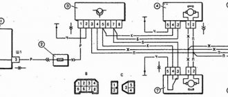
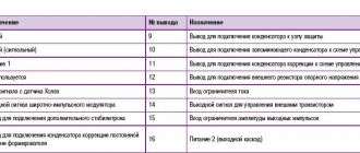
Pinout of the VAZ-2109 ignition switch with unloading relay:
- comes +12V in position I, II, III (parking)
- comes +12V in position I, II, III (parking)
- comes +12V in position III (parking)
- position I, +12V goes out after turning on the ignition (contact 15/2), disappears at start (II);
- position I, +12V goes to the starter (pin 50);
- position I, +12V goes away after turning on the ignition (pin 15), does not disappear when starting II;
- +12V comes from the battery (pin 30);
- comes +12V constantly.
Pinout of the ignition switch VAZ-2110:
- comes +12V for the microphone of the sensor of the inserted key;
- the mass comes when the driver's door is open;
- +12V goes to the starter (pin 50);
- +12V goes out after turning on the ignition (pin 15);
- +12V goes out when the key is inserted to pin 5 of the BSK;
- comes +12V to illuminate the lock cylinder;
- +12V comes from the battery (pin 30);
- not used.
Pinout of lock VAZ-2113, VAZ-2114, VAZ-2115
Pinout of the ignition switch VAZ-2113, 2114, 2115:
- comes +12V for the microphone of the sensor of the inserted key;
- the mass comes when the driver's door is open;
- +12V goes to the starter (pin 50);
- +12V goes out after turning on the ignition (pin 15);
- +12V goes out when the key is inserted to pin 5 of the BSK;
- comes +12V to illuminate the lock cylinder;
- +12V comes from the battery (pin 30);
- not used.
Scheme of VAZ and car ignition switch
The structure of a car ignition switch
- Locking rod
- Frame
- Roller
- Contact disc
- Contact sleeve
- Block
- Protrusion of the contact part.
The lock mechanism is connected to many wires. They continue from the battery, connecting all the electrical devices of the car into a single chain. When you turn the ignition key, the electrical circuit is closed from the “-” terminal of the battery to the ignition coil. As a result, the current passes through the wires to the ignition switch, through its contacts it is directed to the induction coil, after which it returns back to the “+” terminal. As electricity passes through the coil, it generates high voltage, which it transmits to the spark plug. Therefore, the key closes the contacts of the ignition circuit, thereby starting the car engine.
Replacing the ignition switch on a VAZ car
To carry out repair work to replace the ignition switch of a vase, we will need: a screwdriver, a tester and a thin awl. Once you have everything you need, you can begin the repair. On all classic VAZ cars, the ignition switch is located at the bottom, on the left of the steering column. To replace you need:
- Disconnect battery
- Remove the plastic casing by first unscrewing the screws that secure it.
- Then unscrew the two screws securing the ignition switch to the bracket.
- We insert the key and set it to position 0 to disable the anti-theft device.
- Insert the awl into the hole in the bracket and press the latch. Then we take out the lock itself.
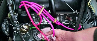
- After removal, it is recommended to mark the contact wires so that nothing is mixed up the next time you connect.
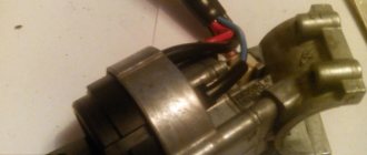
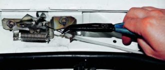
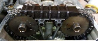
Removing the ignition switch on a VAZ-2106 begins with disassembling the steering column casing. We unscrew the five bolts and remove its halves. Before you begin disassembling the electrical part of the lock, it is very useful to disconnect the battery by removing the negative terminal or unscrewing the switch bolt. After this, remove the spring retaining ring from the back of the lock body and remove the contact group. We move it to the side so that it does not interfere, and we begin to remove the lock itself.
It is secured in the steering shaft bracket with two bolts, after unscrewing which nothing happens. It is useless to try to remove the lock from its socket if you do not know about the special stopper. It is located on the lock body under the bracket. We press this stopper into the lock with a thin screwdriver through a small hole in the bracket. Further, according to all the instructions, the lock should be pulled out freely, but this does not work.
An obstacle that is not described anywhere is the anti-theft rod. Even though it is in a “disconnected” state, it still clings to the steering shaft. To remove the lock, you have to manipulate the key. In different positions of the lock cylinder, the anti-theft device also moves and is recessed as much as possible when the key is in the “Starter” position. After a few minutes the lock can be pulled out of the bracket.
Here is the time to write that assembly of the unit should be carried out in the reverse order of removal. And in general, this will be true. First you need to insert the new lock into the bracket, recessing the latch and holding the key in the starter position, tighten the fastening bolts, then connect the wires. Particular attention must be paid to this, because an incorrectly connected contact group can damage the starter or ignition system. We reconnect the wires from the old group to the new one one at a time, checking the numbers on the contacts. After this, we assemble the steering column casing.
On the car, the ignition switch is located on the driver's side, mounted on the left side of the steering wheel on the steering gear bracket, under the instrument panel.
First of all, you need to get rid of the decorative casing of the steering shaft, unscrew the fastening screws and remove it. We performed similar actions when replacing the steering shaft.
After removing the decorative casing, unscrew the two screws securing the ignition switch to the body, then insert the key into the lock and turn on the “0” position, which turns off the anti-theft device. Through the hole in the bracket, press the lock lock with a thin awl and remove the ignition switch from the mounting socket. This completes the repair work to remove the ignition switch.
On VAZ 2108 and higher models, a package with wires is connected to the lock, that is, nothing needs to be marked and the possibility of mixing up the wires when installing a new switch is completely eliminated. Well, on VAZ 2107 and lower models, this is not the case, each wire is connected separately, so when removing each wire, it must be marked so as not to be confused during further installation.
To replace the contact group of the ignition switch, you need to use a thin screwdriver or an awl to pry the retaining ring from the edge and remove the contact part. When installing a new contact part, orient it so that terminals “15” and “30” are on the side of the locking rod.
At this point, the repair work is completed, install the new ignition switch in the reverse order of removal, connect the wires, transferring the markings from the old switch to the new one. The pinout or connection diagram of the VAZ ignition switch wires is quite simple and understandable, so every car enthusiast can carry out repairs or replace a spare part without the help of car service employees.
Didn't find the information you are looking for? on our forum.
The procedure for disassembling the lock
Before starting work, you should prepare the necessary set of tools. The kit will come in handy with a Phillips screwdriver, a set of keys, a narrow chisel or punch, and round nose pliers with curved ends for gripping. Provide yourself with easy access to the lock and adequate lighting.
At the initial stage, the entire device assembly is removed. The protective element of the plastic casing is sequentially dismantled, the lock is unscrewed and pulled out. To avoid errors during reassembly, mark the installation location and purpose of each wire. Take the time to take a legible photo.
Be sure to evaluate the terminal block with the wires inserted. If cracks or traces of melting are detected, feel free to remove each wire from its socket and replace it with a new part.
We recommend: Car suspension: elements, diagram, types
There is no clear answer to the question of how to remove the ignition switch contact group. It all depends on the design features of the device. Let's consider dismantling the required element using the example of the VAZ model of the 10th family:
- Disconnect the backlight wires if present.
- Disconnect the decorative cover at the top of the device by unlatching the latches around the perimeter.
- Disconnect the contact group. Usually the fastening is also carried out in the form of several clamps.
After removing the part, you should examine the condition of the contacts. Minor oxidation can be removed by simply sanding with medium-sized sandpaper. Do not rush to reassemble. Try to simulate a launch right on the scale.
If burnt contacts are detected or if it is impossible to identify a visible defect, the part should be replaced without regret.
When performing reassembly, consider the sequence of operations. A well-installed lock should not only perform its functions, but also not move with each turn of the key. Please pay attention to the following points:
- the mounting bolts are firmly tightened only if the outer part under the steering wheel is properly installed;
- make a test rotation of the steering wheel without a key to make sure that the locking device is working properly;
- When selecting bolts, do not forget about the ease of access to the lock for potential burglars.
When completing all work and connecting the wires, check that the harness is securely fastened. If everything is done correctly, the first test run will allow you to hear the rustling sound of a running engine.