Ignition systems for gasoline engines of domestic passenger cars VAZ-2108, VAZ-2109, ZAZ-1102 contain an electronic switch. It is designed to generate current pulses in the circuit of the primary winding of the ignition coil.
In domestically produced electronic switches (series 3620.3734; 36.3734; 78.3734), the functions of the output current switch are performed by a powerful transistor, and the functions of controlling the parameters of current pulses (normalizing the duty cycle of triggering pulses, software regulation of the time of energy accumulation in the ignition coil, limiting the current level in its primary winding and amplitude of primary voltage pulses) is performed by a low-current electronic circuit, often in an integrated design.
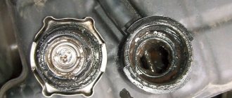
The first domestic electronic switch with controlled parameters of ignition pulses (series 36.3734) was developed for the VAZ-2108 car. The switch used the K1401UD1 microcircuit, a powerful key transistor KT848A and other domestically produced elements.
The input information signal for the switch is the signal from the Hall sensor located on the ignition distributor shaft. Using this signal, the switch receives information about the number of engine revolutions and the position of its crankshaft. The switch is designed to work with a serial ignition coil 27.3705.
The switch was a prototype for the development of subsequent series, which have several design and circuit design options. However, what domestic switches still have in common is a combined integrated-discrete assembly technology, which makes them repairable.
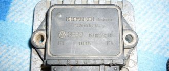
Modern domestic switches use specialized output key transistors of the types KT890A, KT898A1, BU931 (foreign) in several designs: TO-220, TO-3, unpackaged. Some switches, for example 78.3734 (Fig. 4), use a four-channel operational amplifier of the K1401UD2B type as a control chip.
The switches also widely use the L497B control chip from SGS-TOMSON (domestic analogue of the P1055HP1). The block diagram and the recommended option for its inclusion are shown in Fig. 1, and the assignment of the pins is in table. 1.
Before you begin troubleshooting and repairing the electronic switch, you should: • check the integrity of the vehicle wiring, the reliability of the contact connections of the ignition system, the serviceability of the ignition system elements (spark plugs, ignition coil, Hall sensor, high voltage wires); • check the serviceability of the car generator, as well as its integrated voltage regulator; • check the supply of voltage from the on-board network (with the ignition switch on) to contact “P” of the Hall sensor connector.
The signs that indicate malfunctions of electronic switches, the most likely causes of these malfunctions and methods for eliminating them are summarized in table. 2.
Schematic diagrams of the ignition switches are shown in Fig. 2 (switch 3620.3734 - I), fig. 3 (switch 3620.3734 - II) and fig. 4 (switch 78.3734).
In conclusion, the following should be noted:
1. A close analogue of the foreign transistor BU931 (see diagrams in Fig. 2 and 3) is the domestic KT898A1. These transistors have a wide range of parameters, which leads to the need to select the ratings of radio elements in its base and emitter circuits for each individual transistor.
2. Resistors R7 (see Fig. 2) and R6 (see Fig. 3) are used to set the required current value through the powerful key transistors of the described switches.
Increasing the resistor value leads to a decrease in current and vice versa. Thus, by changing the values of these resistors, you can select the optimal current and thermal operating conditions of the output key transistors.
3. When replacing a powerful switching transistor, you should pay attention to the quality of fastening the transistor to the radiator (case) of the switch. They also check the presence of heat-conducting paste between the transistor and the radiator (switch housing).
4. An analogue of the foreign zener diode 1N3029 (see Fig. 3) is the domestic KS524.
5. An analogue of the foreign microcircuit L497B (see Fig. 1, 2, 3) is the domestic KR1055ХП1.
6. After replacing faulty radio elements in the switch, each new element on the board and its soldering area should be coated with nitro varnish. When assembling the switch housing, its cover around the perimeter of the seal must be coated with a waterproof sealant (for example, Germesil).
The switch is an electronic component to ensure the operation of a contactless ignition system. It is transitional between contact and microprocessor. The latter, the most advanced, allows you to control the torque using data read from sensors - oxygen, speed, engine speed and others. But there are still many cars on the roads that have both contact breakers and contactless ones. Therefore, for maintenance and diagnostics, you need to know the purpose of all elements, as well as troubleshooting methods and their main symptoms. Before testing the switch, review all parts carefully.
Contactless ignition system
In total, there are three huge groups of systems - contact, contactless, microprocessor. The first is divided into two subgroups - contact and using a transistor operating in switch mode. Transistors are also used in the design of a contactless ignition system. This scheme began to be actively used in the early 80s of the last century. And it has a number of advantages, which will be discussed below. The switch circuit is simple; it can be implemented both on transistors and on a controller.
But the contactless ignition system also has many disadvantages when compared with a microprocessor one. The latter allows you to control almost all engine parameters. BSZ does not allow this; it also cannot be used normally on injection engines. The reason for the obsolescence of the contactless system lies not only in the development of electronics and the automotive industry, but also in the adoption of stringent measures to ensure the environmental friendliness of internal combustion engines. Unfortunately, only microprocessor control can reduce the amount of harmful substances in the exhaust.
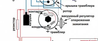
Main elements of the system
Of course, the first thing to mention is the spark plugs. They are installed in the cylinder head, the electrodes come out from the inside. These are the elements that allow the air-fuel mixture to ignite. But with the help of spark plugs alone, the engine will not be able to run. It is necessary to monitor the position of the crankshaft in order to know in what position the pistons are in the cylinders.
For this purpose, an inductive sensor operating on the Hall effect is used. It is part of the design of another element - the ignition distributor. The sensor produces a pulse that is sent to the switch. This device allows you to amplify a weak signal to a voltage of 12 volts, and then apply it to a coil. A coil is nothing more than a simple transformer (step-up). Its secondary winding has a greater number of turns than the primary. Due to this, the voltage increases and the current decreases. The voltage in the BSZ is supplied to the spark plugs at a value of 30-35 kV (depending on the car model).
General information about the Nine ignition system
What elements does the SZ electrical circuit include:
- Coil or module. This device generates a high-voltage discharge and transmits it to the spark plugs via high-voltage cables.
- Candles. These devices are used to transmit a high-voltage pulse to the cylinders of the power unit, where the fuel-air mixture is located. Spark plugs may not work correctly over time, due to wear or carbon deposits on the electrodes. Such problems can lead to incorrect operation of the engine in general, as well as difficulty starting it in particular.
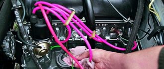
- High voltage wires. They connect the distribution unit with the candles. The performance of high-voltage wires is also important, since if they break down, the driver may also experience incorrect functioning of the internal combustion engine.
- Switchgear. This unit distributes the high-voltage discharge to certain spark plugs, since the cylinders must fire in a certain order. One of the main components of the distributor is the vacuum regulator.
- Switch.
- Mounting block.
- Ignition relay.
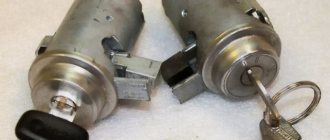
- A switch, that is, a lock. With its help, the driver gives the command to start the engine (the author of the video is Nail Poroshin).
How is BSZ better than contact?
Having carefully read the previous section, you can see that the system uses an inductive non-contact Hall sensor. The advantage is obvious - there is no friction and commutation. For comparison, look at the contact system. In it, the breaker switches the voltage, the value of which is 12 Volts. Whatever one may say, the metal contacts are constantly in contact with each other, gradually wear out, and become covered with soot.
For these reasons, it is necessary to constantly monitor the breaker, adjust the gap, and carry out timely replacement. BSZ is devoid of these shortcomings, therefore, without third-party intervention, the system operates much longer. The Hall sensor fails very rarely, as does the switch. This increases the reliability of the system, but precautions must also be taken, in particular, the connection of the switch to the body must be as tight as possible to ensure effective heat exchange. In addition, BSZ allows you to improve engine performance, increase, albeit slightly, its power, along with increasing reliability.
How does a switch work?
Essentially, a switch is a simple signal amplifier. It can even be compared to a Darlington assembly, which is used in microcontroller technology to convert a weak signal from an output port to the required level. The basis of this assembly is field-effect transistors operating in switch mode. An operating voltage is applied to them, a signal is sent to the control terminal, which is amplified and removed from the collector.
The ignition switch has an almost similar operating scheme. Only the signal from the Hall sensor is used. It has three outputs - control, common, plus power. When a metal plate appears in the sensor area, a current is generated, which is supplied to the input of the switch. Next, the signal is amplified and supplied to the primary winding of the coil. The entire system is powered only after the ignition is turned on (after turning the key).
Basic Switch Elements
The switch circuit is quite simple, but making this unit yourself is pointless, since buying a ready-made version will be much easier. Installation must be carried out as competently as possible, otherwise the device will not operate correctly. In addition, when using transistors, you need to carefully select them according to their parameters, and for this you need to have high-quality measuring equipment. Unfortunately, for two identical semiconductors, the spread of characteristics can be very large. And this affects the operation of the device.
The VAZ switch, designated 76.3734, consists of one main element - the L497 controller. It is designed specifically for use in contactless ignition systems. The domestic analogue of this controller is KR1055HP2. Their parameters are almost identical, which allows you to use any of the controllers. In addition, this chip allows you to connect a tachometer located on the dashboard of the car. But you can also use a simpler circuit, which is an amplifier unit of two stages. True, the reliability of such a device is much lower.
Connecting the switch
Cases vary, and it is possible that you will have to change the wiring. Therefore, you will need to take into account the purpose of all pins on the switch plug. This will allow the connection to be made correctly, and there will be no risk of damaging it. The first pin of the switch is the output. In other words, the amplified signal is removed from it. It must be connected to the terminal of the “K” coil. The second contact is connected to ground - the negative of the battery.
All three wires from the Hall sensor go to the VAZ switch. Moreover, the signal wire is connected to the sixth terminal of the switch. The fifth is the power output (the voltage on it is stable 12 Volts). The third output of the switch is ground (minus power). The third is connected inside the block to the second. But between the fourth, which is supplied with power from the battery, and the fifth there is a constant resistance and a voltage stabilizer.
Practical advice
The operation of an injection power unit, and in particular the maintenance of its electronic components, is fundamentally different from carburetor engine systems.
Owners of converted cars must learn a few basic rules:
Before dismantling the injection control system components, be sure to disconnect the negative cable from the battery terminal;
Working with car wiring requires care and precision.
- Do not start the engine if the terminals of the wires on the battery have poor contact. Be sure to check how tightly they are tightened;
- Do not disconnect the battery while the vehicle engine is running. This is guaranteed to lead to failure of the ECU;
- Monitor the ECU temperature. It is not allowed to overheat (65°C when the car is running and above 80°C, for example when drying in a paint booth). If such a process is unavoidable, remove the ECU from the vehicle for the duration of the work;
- It is also necessary to remove the ECU or disconnect it from the vehicle’s on-board system when carrying out welding work on body parts.
How to check
There is nothing complicated in this procedure. The easiest way is to use a known-good node, since you can check the switch this way in literally a matter of minutes. But if there is none, and you need to determine exactly whether the fault is in the coil or in the switch, it is wiser to use other methods. You will need a simple incandescent lamp. If you don’t know where to get it, then unscrew it from the interior lamp or from the side lights.
Connect one terminal of the lamp to the negative of the battery. Connect the second one to pin “1” of the switch. This is the same pin from which the amplified signal is removed. If the lamp lights up, then the device is working properly. A more advanced testing method is carried out using an oscilloscope. On the screen you can see the magnitude and shape of the signal, and also compare it with the reference one.
Electrical diagram of carburetor VAZ 2109
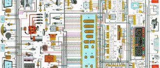
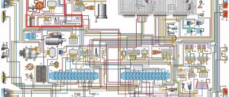
It's no secret that the Russian automobile industry, like foreign cars in general, often has problems with wiring, either mice have chewed on it, or the wiring has been interrupted when driving over potholes, and then you wonder, where can I get a diagram? electrical wiring of my car, in this case I present a wiring diagram for a VAZ 2109 car, in the following articles I will try to post wiring diagrams for other VAZ and UAZ cars, and I will also try to find diagrams for foreign cars with a carburetor engine, so follow the release of articles on the website, I will also hear your wishes and corrections in the comments.
Electrical diagram for VAZ 2109 carburetor: 1. Headlight unit (headlight combined with the front light); 2. Geared motors for headlight cleaners; 3. Temperature indicator sensor; 4 Engine compartment lamp switch; 5. Sound signal; 6. Reversing light switch; 7. Fan motor; 8. Fan motor sensor; 9. Headlight washer valve; 10. Generator; 11. Rear window washer valve; 12. Windshield washer valve; 13. Window washer motor; 14. Engine compartment lamp; 15. Spark plugs; 16. Plug socket for a portable lamp; 17. Sensor; 18. Ignition distributor sensor; 19. Carburetor electromagnetic valve; 20. Limit switch in the carburetor: 21. Switch: 22. Ignition coil; 23. Diagnostic block; 24. Sensor c. M.T. 25. Rechargeable battery; 26. Brake fluid level sensor; 27. Starter; 28. Carburetor valve control unit; 29. Additional starter activation relay; 30. Windshield wiper motor; 31. Illumination lamp for the heater control panel; 32. Heater fan electric motor; 33. Additional resistor; 34. Heater motor switch; 35. Cigarette lighter; 36. Glove box lighting lamp; 37. Mounting block: 38. Instrument cluster; 39. Brake light switch; 41 Parking brake warning lamp switch; 42. Carburetor air damper warning lamp switch; 43. Instrument lighting switch; 44. External lighting switch; 45. Hazard switch; 46. Rear fog light switch; 47. Rear window heating switch; 48. Side direction indicators; 49. Light switches in the front door pillars; 50. Light switches in the rear door pillars (for VAZ-2109); 51 Interior lighting; 52. Ignition switch; 53. Switch for windshield wipers and ordinary people; 54. Horn switch; 55 Switch for direction indicators, parking lights and headlights; 56. Rear lights; 57. Fuel level indicator sensor; 58. Rear window heating element; 59. License plate lights; 60. Rear window wiper motor A. Wire tip for connecting to the brake pad wear sensor; B. Plug connector for connecting to the interior lamp for individual interior lighting; I. Conventional numbers of plugs in the mounting block blocks; II. Numbering of plugs in the motor reductor block; III. Conventional numbers of plugs in the block and contacts of the ignition switch; K1. Rear window washer timing relay: K2. Relay-breaker for direction indicators and hazard warning lights; KZ. Windshield wiper relay; K4 Contact jumpers at the installation site of the lamp health monitoring relay; K5. Headlight high beam relay; KB. Headlight cleaner activation relay; K7. Power window relay (not installed); K8. Horn relay; K9. Fan motor relay; K10. Heated rear window relay; K11. Relay for low beam headlights. Electrical diagram of VAZ-21093 and VAZ-21099 luxury cars with a high instrument panel (clickable). 60 — rear window heating switch; 61 — fog lamp switch; 62 — control lamp for turning on fog lights; 63 — indicator lamp for turning on the rear fog light; 64 — rear fog light switch; 65 — side direction indicators; 66 — lamp switches on the door pillars (on VAZ-21093 and VAZ-21099 there are four); 67 — fog light circuit fuse; 68 — external lighting switch; 69 — instrument cluster; 70 — carburetor air damper warning lamp switch, 71 — hazard warning switch; 72 — lampshade; 73 — connector for connecting to the individual lighting lamp; 74 — rear lights; 75 — license plate lights; 76 — electric motor for rear window wiper; 77 — rear window heating element; 78 — sensor for level indicator and fuel reserve. Diagram of electrical equipment of cars PVAZ-21083, VAZ-21093 and VAZ-21099. 80 — blocks for connecting to an additional brake light 81 — license plate lights; 82 — sensor for level indicator and fuel reserve. The order of conditional numbering of plugs in the blocks: A - headlight units, headlight and rear window cleaners; B — mounting block, instrument cluster of the ignition switch, windshield wiper and door lock control unit (for blocks with a different number of plugs, the numbering order is similar); B — gear motors for power windows and gear motors for locking door locks; G — ignition distributor sensor; D — switch and carburetor solenoid valve control unit; E — rear lights (pin numbering in order from top to bottom); F — interior lamp; 3 — fuel level sensor. In the instrument panel wiring harness, the second ends of the white wires are brought together to one point, which is connected to the instrument lighting switch, the second ends of the thin black wires are also brought together to points connected to ground. The second ends of the yellow wires with a blue stripe are brought together to a point connected to plug 4 of block X1 of the mounting block. And the second ends of the orange wires are also brought together to a point connected to the orange wire with a blue stripe going to plug 3 of block X4 of the mounting block. The diagram shows the connection of all additional electrical equipment, but a vehicle of a particular configuration may not have one or another auxiliary unit or system. Not installed on vehicles equipped with a carburetor with a semi-automatic starting device.
Ignition settings
When setting up the ignition, you will need to do the most important thing - install the shafts according to the marks so that the gas distribution functions synchronously with the operation of the piston group. This is the first thing you should do before you start adjusting the ignition. It is worth noting that there should not be any particular difficulties during setup, especially on VAZ 2108-21099 cars. The thing is that the ignition distributor on the engines of these machines can only be installed in one position. Moreover, the ignition switch does not undergo any settings during this procedure, since it does not have any.
The distributor body rotates around its axis to make more precise adjustments. And this turns out to be enough. To accurately set the torque, you can use a simple circuit that uses a simple LED as an indicator. The Hall sensor is disconnected from the system, and positive power is supplied to its negative terminal. An LED is switched on between “+” and the signal LED, and a 2 kOhm resistance is connected in series with it to reduce the voltage. But the plus of the Hall sensor is connected to ground. Now all that remains is to slowly rotate the distributor housing. The moment when the diode lights up will be the desired one.
Diagram of the EPHH system of carburetor 2108, 21081, 21083 Solex
Solex carburetors 2108, 21081, 21083 of VAZ 2108, 2109, 21099 cars have a forced idle economizer system (EFI). It allows you to forcibly turn off the fuel supply through the idle system in a certain speed range, which ensures some engine efficiency. Below is an electrical diagram of the EPH system of these carburetors.
Diagram of the EPH system of Solex carburetors 2108, 2109, 21099
Notes and additions
— In some cases, if problems arise with the EPH system, the carburetor solenoid valve is connected with a piece of wire to the “plus”, for example from the positive terminal of the battery or one of the ignition coil terminals. It should be noted that in this case the valve will be constantly powered, its needle will be retracted, and the CXX fuel jet will be open at different engine operating modes. This will lead to a slight increase in fuel consumption. Also, a constantly energized valve will discharge the battery. Therefore, if problems arise with the EPH, it is better to either turn off the system altogether (by breaking the valve needle) or bring it into serviceable condition.
More articles on Solex carburetors
— Checking and repairing the EPH system of the Solex carburetor
— Features of installing a solenoid valve on Solex and Ozone carburetors
— Solex carburetor adjusting screws
— Solex carburetor jets
— Adjusting the idle speed of an engine with a Solex carburetor
conclusions
Many advantages are provided by such a simple unit in a contactless ignition system as a switch. This includes an increase in power, even if only slightly, a reduction in fuel consumption, and a significant improvement in the engine in terms of reliability. And most importantly, there is no need for constant monitoring and timely adjustment of the system. The modern driver does not want to repair a car, he needs a means of transportation. Moreover, it is reliable and will not let you down at the most crucial moment. Regardless of which switch is used in the BSZ, its efficiency is much higher than that of a contact breaker.
The VAZ 2108 switch provides the formation of control pulses supplied to the ignition coil. This element of the vehicle's electrical equipment is an electronic device that ensures the normal functioning of the vehicle's contactless ignition system.
This component of the vehicle's electronic ignition system is surface mounted and is robust enough to withstand the high vibration and shock loads that may occur during vehicle operation. The device implements the maximum possible protection options for electronic components.
Ignition system VAZ 2109 operating principle and adjustment
The VAZ repair zone recommends using tire fitting equipment, which can be ordered here. Equip your workshop only with high-quality equipment!
Distributor VAZ 2109
A fairly simple ignition system of the VAZ 2109 ensures stable operation of the engine and its normal functioning.
Today we will look at the principle of operation and the main components of the system on a VAZ 2109 car with a carburetor injection system, and also focus on adjusting the advance angle
The principle of operation and composition of the ignition system on a VAZ 2109 car
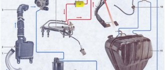
To understand the principle of operation, it is necessary to study the composition. The ignition system of the VAZ 2109 car includes the following elements:
- Hall sensor (non-contact).
- Ignition distributor (popularly called simply distributor).
- Electronic switch.
- Armored wires.
- Ignition coil.
- Candles.
The essence of the system is to timely supply a high voltage pulse to the electrodes of the spark plugs. When the starter rotates, motion is transmitted to the camshaft, from which the distributor rotates. The design of the latter contains a Hall sensor, in the immediate vicinity of which a kind of metal “skirt” with slots rotates. When a metal part passes near the sensitive element of the sensor, voltage appears on the signal wire.
The signal is sent to an electronic switch - the second most important element of the VAZ 2109 ignition system with carburetor injection. The resulting pulse is amplified and fed to a coil, which consists of two windings connected at one point. But in fact, the coil is a step-up transformer; similar designs are installed even in microwave ovens. As a result, the voltage increases hundreds of times - from 12 Volts to 30 thousand Volts. True, the current strength is very small, so a spark strike can only cause unpleasant sensations and does not pose a risk to life.
High voltage is supplied to the ignition distributor, which is necessary for one main purpose - distributing current to the corresponding cylinders, according to the operation of the engine. When high voltage reaches the spark plug, a breakdown occurs - a spark is formed between the electrodes, which can ignite a mixture of gasoline and air. Perhaps, a simplified story about the principle of operation of the ignition system of a VAZ 2109 car can be considered complete. All that remains is to talk about how to correctly adjust the ignition timing.
How is the ignition adjusted?
There are several methods you can use:
- Aurally.
- Using a strobe light.
- Using a motor tester.
The latter, of course, will be the most preferable. But if suddenly there is a need to adjust the ignition of the VAZ 2109 in the field, then you can use the first method. If you have to frequently carry out adjustments, you can solder a small circuit on one thyristor with your own hands. In a matter of minutes, you can make a strobe light from a flashlight with your own hands.
Before starting work, make sure that the camshaft and crankshaft are installed strictly according to the marks. Open the inspection window in the clutch housing; through it you can see the flywheel and the marks on it. Remove the protective cover from the timing compartment, align the camshaft pulley to the mark. Check by looking through the inspection window to see if the mark on the flywheel aligns with the bar attached to the engine block.
Without this inspection, it is impossible to correctly adjust the ignition on a VAZ 2109 car. The operation of the valves will be disrupted and the engine will not function properly. Now, armed with a 10mm wrench, loosen the three bolts (but do not unscrew) that secure the distributor housing. Start the engine and warm it up.
Now turn the distributor body to the side (you will find two inscriptions “+”, “–” and dashes). Accordingly, “–” means early ignition, and “+” later
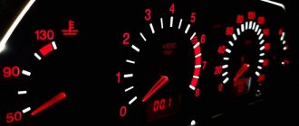
Change your position a little, listen to the engine, depress the gas pedal and notice how the speed increases
Your guideline should be this - the crankshaft speed at normal settings should be 700-900 per minute. But adjusting the ignition of the VAZ 2109 using a strobe light is much more accurate, it’s just a pity that not everyone has such a device.
A very interesting video about the ignition system of the VAZ 2109 and not only:
https://youtube.com/watch?v=Ud-nuLSxwvk
Switch Specifications
The VAZ switch circuit is based on the L497 microcircuit, which controls the output NPN transistor. A special feature of the microcircuit is the ability to program the recovery time of the delay coefficient, which is important for trouble-free starting of a cold car power unit. This feature of this electronic component of the switch allows for rapid acceleration of the crankshaft speed without failures in operation, which ensures constant engine traction.
Analogues that are sometimes used in the design of the VAZ 2108 switch are the KR1055HP1, KR1055HP2, KR1055HP4 microcircuits. However, these electronic components are found quite rarely in the design of the device. Main technical parameters of the device:
- optimal operating voltage 13.5 V;
- voltage range for normal operation 6-16 V;
- switching current 7.5-8.5 A;
- the range of ensuring uninterrupted sparking is from 20 to 7000 crankshaft revolutions.
How to recognize switch faults
Ignition problems are always accompanied by characteristic symptoms that every car owner should be aware of. One of these faults is related to the switch.
Here are just the most common signs indicating problems with the operation of the VAZ 2108 switch.
- The engine cannot be started.
- The starter actively turns the engine flywheel, but there is no spark.
- The engine can be started, it idles, it can be raised to medium speeds, but it is impossible to increase the speed to maximum.
- The motor is not running at full power.
- At idle, the engine runs fine, but begins to stall when trying to start.
- The engine can be started, but it stalls after a short time.
- One of the cylinders refuses to work at a certain speed (troit).
- The engine stalls when hot and continues to run normally when it cools down.
- The battery discharge lamp is on.
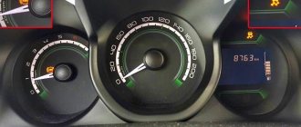
- The tachometer shows sharp jumps in engine speed.
These are just the most common, but not the only features of a faulty switch. There are also a number of indirect signs. Sometimes even experienced technicians cannot immediately identify the symptoms of malfunction of this unit of the VAZ 2108 ignition system.
How to test a switch
On average, the cost of this part is not too high, but many car owners, for various reasons, do not seek to replace it. In addition, if you change a known-good switch, problems with the engine will remain, because the cause of malfunctions in the operation of the power plant may be completely different. Therefore, the optimal solution would be to check the part for functionality.
For accurate diagnostics, you will need special professional equipment, which is available at any service station. On a special stand you can check the pulse on the ignition coil, its stability and cyclicity. However, it is not always possible to turn to specialists; there is also a simpler folk diagnostic method. To check, you should take a key for an 8 and 12-volt light bulb with a power of 3 W. The algorithm of actions is as follows.
- Disconnect the power supply by disconnecting the terminals from the battery.
- Using a key number 8, you need to disconnect the brown wire that goes from terminal K on the ignition coil to terminal 1 on the switch.
- One contact of the control light is connected to the terminal on the ignition coil, and the other to the switch. As a result, the control lamp becomes part of the circuit between the coil and the switch.
- Connect the terminals to the battery and try to start the engine (the lamp should light up while the starter rotates).
A light that comes on indicates that the switch is working properly. If this does not happen, the unit is faulty and needs to be replaced. When disconnecting the light bulb, be sure to disconnect the negative terminal from the battery, thereby preventing the possibility of an accidental short circuit.
The installation location of the device is a partition separating the engine compartment of the car from its interior. The device is mounted in the engine compartment. The connection diagram of the switch must ensure reliable contact between the base of the device and the car body. The device can operate normally up to a heating temperature of 115 °C.
Full scheme
1 – block headlight; 2 – gear motor for headlight cleaner*; 3 – engine compartment lamp switch; 4 – sound signal; 5 – electric motor of the engine cooling system fan; 6 – fan motor activation sensor; 7 – generator; 8 – solenoid valve for turning on the headlight washers*; 9 – solenoid valve for turning on the rear window washer* (not installed on the VAZ-21099); 10 – solenoid valve for turning on the windshield washer; 11 – electric motor for glass washer; 12 – oil pressure warning lamp sensor; 13 – carburetor solenoid valve; 14 – carburetor limit switch; 15 – spark plugs; 16 – plug socket for a portable lamp; 17 – engine compartment lamp; 18 – ignition distributor sensor; 19 – carburetor solenoid valve control unit; 20 – windshield wiper gearmotor; 21 – switch; 22 – ignition coil; 23 – starter; 24 – top dead center sensor of the 1st cylinder**; 25 – diagnostic block**; 26 – starter activation relay; 27 – coolant temperature indicator sensor; 28 – reverse light switch; 29 – battery; 30 – brake fluid level sensor; 31 – mounting block; 32 – parking brake warning lamp switch; 33 – brake light switch; 34 – glove box lighting lamp; 35 – heater fan electric motor; 36 – additional resistor of the heater electric motor; 37 – heater fan switch; 38 – backlight lamp for heater levers; 39 – cigarette lighter; 40 – rear window heating switch; 41 – rear fog light switch; 42 – fog light circuit fuse; 43 – alarm switch; 44 – external lighting switch; 45 – ignition relay; 46 – ignition switch; 47 – steering column switch; 48 – instrument lighting switch; 49 – side direction indicator; 50 – lamp switch on the front door pillar; 51 – lamp switch on the rear door pillar (not installed on VAZ-2108 and VAZ-21083); 52 – lampshade; 53 – sockets for connecting individual interior lighting to the lampshade; 54 – switch for the carburetor air damper warning lamp; 55 – turn signal indicator lamp; 56 – indicator lamp for external lighting; 57 – rear fog light indicator lamp; 58 – backup warning lamp; 59 – control lamp for high beam headlights; 60 – indicator lamp for heated rear window; 61 – speedometer; 62 – instrument cluster; 63 – instrument cluster lighting lamps; 64 – coolant temperature indicator; 65 – voltmeter; 66 – fuel level indicator with reserve indicator lamp; 67 – econometrician; 68 – “STOP” indicator lamp; 69 – battery charge indicator lamp; 70 – control lamp for the carburetor air damper; 71 – hazard warning lamp; 72 – brake fluid level warning lamp; 73 – parking brake warning lamp; 74 – oil pressure warning lamp; 75 – rear light; 76 – sensor for level indicator and fuel reserve; 77 – pads for connecting to the rear window heating element; 78 – license plate lights; 79 – rear window wiper gear motor* (not installed on VAZ-21099)
Checking and replacing the device
When checking and repairing a car’s contactless ignition system, it is imperative to check the functionality of the switch. To test this device, you need to have a standard set of tools on hand. In addition, you will need a control light with a voltage of 12 V.
A full check of the element is carried out on a specialized stand, which allows not only to determine the presence of an impulse, but also its duration. Using a test lamp makes it possible to determine the presence of only a pulse when testing the device at home. To check the operation of the switch, you need to do the following operations.
- It is necessary to de-energize the vehicle's on-board network. This is done by disconnecting the negative terminal of the battery from the electrical circuit.
- Using an open-end wrench No. 8, terminal “K” is disconnected on the ignition coil, which has a red-brown wire connected to terminal “1” of the contact block of the switching device.
- The disconnected wire is connected to its terminal on the ignition coil through a light bulb, after which the negative terminal of the battery is connected to the on-board network. When the starter is turned on, the lamp should flash. The absence of blinking indicates that the switch is faulty.
When operating a car, in order to avoid failure of the switch, it is necessary to periodically clean the surface of the cooling radiator.
Ignition circuit for VAZ 2109
Every owner of the VAZ 2109 should know the ignition circuit. Without knowing this circuit, you will not be able to start the car in case of ignition problems. Moreover, this scheme is elementary simple. The VAZ 2109 is equipped with a contactless ignition system. It consists of the following components: switch, ignition coil, distributor, Hall sensor, high-voltage wires and spark plugs. The task of the ignition system is to provide a timely, cyclic spark to the engine cylinders. Let's take a closer look at how the clamping circuit works.
Ignition circuit for VAZ 2109
ignition of the VAZ 2109: power is supplied to the ignition system through a relay. Until the key is in the ignition position, the relay will not turn on and supply power to the circuit. As soon as the key is turned, the ignition system is energized. +12V power from the battery is supplied to contact B of the ignition coil, the 4th contact of the switch. The Hall sensor powers the switch itself
Please note that the ignition relay is powered through the mounting block, and if there is poor contact in connectors Ш1, Ш8 or for some reason the track oxidizes or burns out, the ignition system will not be powered and the VAZ 2109 will not start. In order for a spark to begin to form, you must crank the engine crankshaft.
Together with it, the camshaft will turn and the Hall sensor will send an impulse to the switch. The commutator, in turn, will connect contact K of the ignition coil to ground, resulting in a spark appearing on the central wire. When the distributor slider connects the central wire and the wire leading to a specific engine cylinder, a spark will jump on the spark plug, igniting the combustible mixture. The engine will start. When it is necessary to turn off the engine, the driver, by turning the key in the ignition switch, turns off the relay, which in turn disassembles the power supply to the system. The switch and ignition coil become de-energized and stop working. The most common malfunctions of the VAZ 2109 ignition system: 1) Failure of the switch. 2) Failure of the Hall sensor. 3) Poor contact of the slider in the distributor. 4) Lack of power supply to the ignition system of the VAZ 2109. Go to Home.
The article was written based on materials from the sites: wiki.zr.ru, autocentrum.ru, vaz2109.net.