Where is the Hall sensor located and what does it look like?
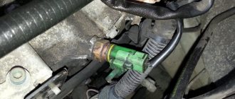
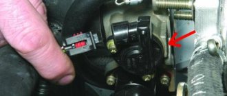
The Hall sensor is located in the distributor - more precisely, inside its cover. Remove it and you will see the sensor. It is responsible for generating a spark and acts as distributor contacts in a contactless ignition system. This is a controller that transmits information about the position of the motor system shafts to the control unit.
Externally, the device looks like a cylindrical element enclosed in a plastic case, to which a connector with wiring is connected. On top of the case is a magnetically conductive plate, which resembles a crown due to the slots. There are as many slots on it as there are cylinders in the engine. The main elements of the device are a permanent magnet and, in fact, a sensor.
Hall sensors: operating principle, types, application, how to check
An electromagnetic device called a Hall sensor (hereinafter referred to as Hall sensor) is used in many devices and mechanisms. But its greatest application was found in the automotive industry. In almost all models of the domestic automobile industry (VAZ 2106, 2107, 2108, etc.), the non-contact ignition system for a gasoline engine is controlled by this sensor. Accordingly, when it fails, serious problems arise with the operation of the engine. In order not to make mistakes when diagnosing, it is necessary to understand the principle of operation of the sensor, know its design and testing methods.
Why does the Hall sensor fail?
Damage to the sensor can manifest itself with different symptoms - even a professional can sometimes find it difficult to determine the exact cause. Here are the signs that indicate a sensor failure:
- the engine does not start well;
- idling with constant interruptions;
- at high speeds the car jerks;
- the spark on the candles disappears;
- the engine suddenly stalls.
The main reason for the failure of this part is trivial - dirt has accumulated. As soon as this happens, the DH signals immediately. “Miracles” begin to happen to the car. However, it is wrong to blame this device for all the troubles - a thorough check is needed.
A common cause of failure is a lack of contact in the wiring. In total, the device has 3 contacts - connecting it to ground, to plus, to the switch. One of the contacts could have oxidized, causing the electrical circuit to break.
Finally, the wire may simply break or break. This occurs due to the fact that the vacuum ignition corrector displaces the platform on which the DC is located, shifting the ignition angle. To avoid such a misfortune, the wiring must be secured so that it bends in a loop.
If the high-voltage wiring in the car is worn out and lies next to the sensor wires, a high-voltage breakdown is possible. Often breakdowns occur in wet weather, when the wheel drives into a deep puddle.
A breakdown may occur due to overcharging of the battery generator - when the DC experienced too much load and one of the parts burned out at the input of the switch.
How to check the Hall sensor in the distributor?
A common way to check is to simulate the presence of a sensor. This is the most effective way. It is suitable when there is electricity in the ignition system components and in the complete absence of a spark.
To check from the distributor, we remove the block for connecting the plugs. Then we activate the ignition of the car and, using small pieces of wire, close outputs 2 and 3. If there is a spark on the middle wire of the ignition coil, it means that the sensor has died for a long time. To detect the formation of a spark, we place the high-voltage wiring next to the ground.
Ring with a multimeter
It is necessary to measure the voltage that is generated at the output of the controller. If the device is working properly, the voltage will be within 20 volts.
First of all, you will have to remove the cover from the block connected to the distributor. Next we proceed like this:
- dismantle the main shielded wire from the distributor;
- connect it to ground (to prevent the risk of accidental discharge);
- activate the ignition;
- remove the distribution block;
- set the multimeter to the DC 20 V position;
- We connect the negative probe to ground;
- We will need the positive one to measure the voltage.
There are 3 multi-colored wires on the distributor block. On red, the voltage should be around 12 V. The same value is the norm for the green wire. But on white it should be zero. If the device is in sound mode, a ringing sound will appear when the probe touches the white wire. This is evidence of a normal connection of the wire to ground.
This is how we made sure that all impulses were present on the DH. Now we take small nails prepared in advance and insert them: one into the green (middle) wire, the other into the white (ground). We mount the block into the distributor. Carnations act as conductors. The fact is that on the other side of the block there is no contact base, and the wiring cannot be exposed. We bring the positive probe to the middle wire, the minus probe to ground. The device should show 11.2 V (approximate value). We turn the crankshaft. If at the lower point the readings correspond to 0.02 V, and at the upper point 11.8 V, this is normal. Significant deviations from these readings indicate a problem.
other methods
If the symptoms of a Hall sensor malfunction do not convince you that it is the problem, you can try measuring the resistance on the sensor. Here you yourself will have to act as a designer and make a device whose constituent parts are:
How to replace a Hall sensor on a car?
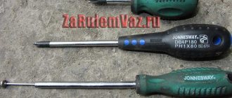
Since repairing a faulty DC is impractical, we prepare the tools and begin to replace it. You will need:
We proceed according to this scheme:
- We turn off the engine and open the hood.
- Disconnect the pipe from the vacuum regulator.
- Remove the distributor cover.
- Disconnect the connector on the DH.
- We unscrew the holder plate with the “13” key. After this, you can remove the distributor.
- Take a hammer and use it to knock out the spring clutch screw.
- Remove the screws securing the vacuum regulator. We pull it out - access to the household is open.
- Using a screwdriver, unscrew the screws securing it and remove the mechanism. We replace it with a new one.
Assembly is done in reverse. After completing the procedure, be sure to drive the car to make sure everything was done correctly.
The reasons for the failure of the Hall sensor are different, but in any case the sensor must be replaced immediately. Repairing the device is useless - you shouldn't even think about it. However, before dismantling the Hall device, make sure that it is the one causing all the problems.
A modern car is equipped with many sensors that signal various processes occurring inside and outside the car. Thus, the speedometer works thanks to a sensor that measures the speed of the wheels, while the lambda probe measures the amount of oxygen in the exhaust gases. The task of the Hall sensor is to participate in determining the ignition timing, without which normal engine operation would be impossible.
Symptoms of DC malfunction
Burnt hall sensor
DH defects manifest themselves in different ways. And this does not mean that if the driver is experienced and understands automotive equipment, he will be able to immediately identify malfunctions. It often takes a long time to analyze and check the signs before you are sure that the sensor has definitely failed.
However, there are several clear symptoms that indicate problems with HD. These should be considered:
- if the car engine does not start or it starts with difficulty;
- if in idle mode the internal combustion engine operates jerkily and intermittently;
- if the engine stalls while driving;
- if the car jerks when driving at high rpm.
If one of these symptoms occurs, it is recommended to question the DH and have it checked. Of course, there are other types of faults associated with DH, but these 4 are the most common.
Purpose and principle of operation of the Hall sensor
The Hall sensor takes its name from the name of the inventor who discovered the galvanomagnetic phenomenon in 1879. Its essence lies in the occurrence of a potential difference when a conductor is placed in a magnetic field, which causes the flow of direct electric current to it. The sensor uses the effect described above in the conditions of a conductor installed under voltage inside the device, which is affected by a magnetic field that crosses it across and creates an electromotive force.
The operating principle of the device is based on detecting the presence or absence of a magnetic field. When the induction force reaches a certain value, the sensor indicates the presence of a field. If the indicator is below the set value, the sensor indicates its absence. The sensitivity of the device is determined by the ability to detect a magnetic field of varying inductance, and can vary depending on the necessary requirements.
An automobile Hall sensor is designed to measure pulses, on the basis of which the electronics of the ignition control unit commands the formation of a spark at the required moment. Structurally, the device consists of the following parts:
- Permanent magnet.
- Steel screen with several cut holes.
- Semiconductor wafers.
A connector containing 3 terminals comes out of the sensor:
- The first output is connected to ground.
- The second is for connecting 6 V voltage.
- The third one supplies the converted pulse signal to the switch.
In most cases, the sensor is located on the distributor. It detects the moment a spark is given and is used instead of contacts. There is a digital modification of the sensor, which can be bipolar or unipolar. The first type is triggered when the polarity changes, and the second when a field appears.
Purpose of DC in the car ignition system
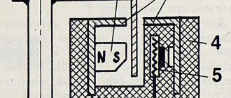
Having understood the principle of operation of the Hall element, let's consider how this sensor is used in the contactless ignition system of the VAZ line of cars. To do this, let's look at Figure 5.
Rice. 5. Principle of the SBZ device
Designations:
- A – sensor.
- B – magnet.
- C – plate made of magnetically conductive material (the number of protrusions corresponds to the number of cylinders).
The operating algorithm of such a scheme is as follows:
- When the chopper-distributor shaft rotates (moving synchronously with the crankshaft), one of the protrusions of the magnetically conductive plate takes a position between the sensor and the magnet.
- As a result of this action, the magnetic field strength changes, which causes the DC to operate. It sends an electrical impulse to the switch that controls the ignition coil.
- The voltage required to form a spark is generated in the Coil.
Signs of a Hall sensor malfunction
Malfunctions of the Hall sensor can have various symptoms, based on which even an experienced technician is not always able to immediately identify the failure. The most typical symptoms of sensor failure are as follows:
- The engine starts poorly or does not start at all.
- When driving a car at high speeds, jerking occurs due to engine operation.
- Engine idling is characterized by jerks and interruptions.
- The engine stalls when driving.
Examination
The health of the Hall sensor can be checked in the following ways:
- By installing a known-good sensor in place of the one being tested. If the problems disappear when you start the engine, then the “original” sensor is faulty and needs to be repaired or replaced.
- Measurement of the sensor output voltage with a tester. A working device will show voltages ranging from 0.4 to 11 V.
- By creating an imitation of the sensor by removing the three-pin block from the distributor, connecting wires 3 and 6 of the switch output and turning on the ignition. A spark that appears indicates a breakdown of the sensor.
What is a Hall sensor?
The sensor is one of the elements of the vehicle ignition system, simple in design, but very important for the operation of the power unit. On older vehicles and some domestic models, it is used as a contact breaker and is located inside the distributor housing. In the design of more modern cars, which have a non-contact ignition system, DC is used to determine the position of two shafts - the crankshaft and the camshaft.
A malfunction of the device leads to problems in the operation of the power unit. They can be solved by checking the Hall sensor, based on the results of which it is repaired or replaced. Although in most cases, a device that is highly reliable can operate without breakdowns for several years. And it fails, most often, due to physical impact or severe contamination.
Hall sensor replacement
Replacing the Hall sensor is a fairly simple operation that even a novice car enthusiast can perform independently. All actions are carried out in the following order:
- Dismantling the distributor.
- Remove the distributor cover and align the timing marks with the crankshaft mark.
- Fix the position of the distributor, then use a wrench to unscrew the fasteners.
- Remove the stoppers and clips.
- Remove the shaft from the distributor.
- Disconnect the terminals on the sensor and unscrew it.
- Carefully pull out the faulty device through the gap created when the regulator was pulled back.
- Installation of a new Hall sensor is carried out in the reverse order.
The hall sensor is a modern element of the car ignition system, which has many advantages over the long-forgotten contact group, which gives the car owner a lot of trouble. However, the hall sensor (HL) can also fail in some cases, although it is not equipped with any mechanical components.
According to experts, if the DC often fails, this is either evidence of a non-original ignition coil (for example, if the old contact ignition system was modernized, but the coil was not changed), or a broken insulation and short circuit.
Hall sensor repair
The design of the Hall sensor is quite simple, and the device rarely fails. But when it breaks down, the car becomes immobilized, and the part requires urgent replacement. Since the sensor is quite expensive, especially for foreign cars, it makes sense to try to repair it yourself. For example, you can take a Volkswagen car device, which is installed on various models of cars from this automaker.
The most unreliable part of the sensor is the S441A logic element, which is the sensitive part of the device, which fails. The purpose of repair is to replace it. The procedure itself consists of the following steps:
- Purchasing a failed element or its equivalent.
2. Checking the part for functionality. For this purpose, an LED and a resistor (1 or 2 kOhm) are connected in series and attached to the “+” and “output” contacts. The current value should vary from 3 to 30 V, and the serviceability of the element is checked with a magnet: when exposed to it, the LED is activated.
3. Use a drill and a metal drill to make a hole in the center of the Hall sensor, cut the wires “flush” with a knife, and use a file to lay grooves from the hole made to the outputs of the remote wires.
4. Placing the active element in the completed window and checking its functionality. So, when the contacts are connected and the curtain passes through the slots, the LED should light up, and when the magnetic flux closes, it should go out.
5. If the circuit refuses to work, the element is turned over and tested again (the polarity of the location matters).
6. If the test was successful, the element leads are routed in the grooves of the housing. In the window itself, the wires that go to the connecting connector of the old sensor are soldered. Pay attention to the correct sequence of wires and their coincidence with the markings of the distributor connector (“+”, “0”, “-”).
7. Having completed soldering, check visually and with a tester for the absence of short circuits in the sensor. If the test is successful, seal the technological hole with heat-resistant glue.
8. The sensor is put in place and the circuit is checked for the absence of short circuits: none of the wires should contact the housing.
The sensors of many cars are restored in the same way. In addition to Volkswagen, devices for Daewoo, AUDI, Mitsubishi, etc. can be repaired, since their operating principle is the same in all cases.
About the hall sensor in detail
ATTENTION! A completely simple way to reduce fuel consumption has been found! Don't believe me? An auto mechanic with 15 years of experience also didn’t believe it until he tried it. And now he saves 35,000 rubles a year on gasoline! Read more"
DCs are available in various modern automotive systems. Elements have been created to communicate important information to the ECM (electrical control system of the internal combustion engine). The latter concerns any changes occurring in the operation of the motor. The ignition system is no exception - and it is equipped with its own sensor, which takes on the task of monitoring normal functioning.
Speaking in purely scientific language, the DH is designed to calculate the angle of position of the motor shafts.
Interesting point. On modern high-class cars such as Audi, BMW or Volkswagen, the DH performs much more functions. But old-type car models equipped with a contact system imply a DC as an integral element of the distributor.
Even on domestic models, such as GAZ 24, “eight”, “nine”, etc., DH is installed, and the ignition system is modernized.
The DC operates on the principle of the voltage increasing effect. In other words, it is a very sensitive element that instantly responds to impulses. In this case we are talking about magnetic field pulses affecting the conductor. As soon as the car's ignition is turned on, the electromotive force in the ignition system changes, which forces the DC to use the switch and spark plugs (SZ).
The DC detects pulses that appear after a change in the magnetic field. The latter occurs during the rotation of the camshaft. However, for the sensor to be activated, a specific value of magnetic induction is needed.
To more fully understand the operating principle of DH, you need to imagine the following:
- a crown plate with slots (the number of slots determines the number of cylinders of the internal combustion engine) on the distributor drive;
- permanent magnet on the camshaft sensor.