The Hall sensor takes its name from the American physicist Edwin Hall . It was he who drew attention to the following physical phenomenon: when a rectangular plate of semiconductor material is placed in a magnetic field and current is supplied to its short sides, a voltage is generated on the long sides.
This discovery occurred back in 1879, but it was only possible to apply it in industry in the second half of the twentieth century, after mass production of semiconductor films was established.
Currently, the Hall sensor is used in various fields. It is especially widespread in the automotive industry: it is used to control the rotation and movement of components and mechanisms, and ensures the functionality of the contactless ignition system.
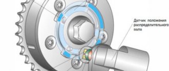
Hall sensors used in a car: crankshaft position sensor, phase sensor or camshaft position sensor, ABS sensor, speed sensor.
Today we will talk about the Hall sensor, which ensures the correct operation of the ignition system in a car.
Why is a Hall sensor needed in a car?
The device is used instead of contact elements and can be used to monitor the load current. Thanks to this sensor, the engine is deactivated when current overloads occur in the on-board network. If the controller overheats, temperature protection is activated.
Principle of operation
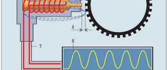
Voltage surges in the motor electrical network can have consequences for the sensor. Therefore, modern devices are additionally equipped with diode elements that prevent reverse voltage activation. The operating principle of the device is based on the Hall effect. A transverse potential difference is formed when one of the conductors moves into a magnetic field. This effect is achieved due to the fact that currents pass through the terminal elements of the plate, which is located in the field itself, with the semiconductor.
When the engine is running and the power unit shaft rotates, the steel blades move along special slots installed inside the housing. This helps to supply an electrical signal to the switching device. As a result, the node opens the transistor element and supplies voltage to the coil. The latter performs the procedure of converting a low-voltage pulse into a high-voltage one. This signal is sent to the spark plugs.
The Radio Amateur TV channel spoke in detail about the principle of operation of the Hall controller.
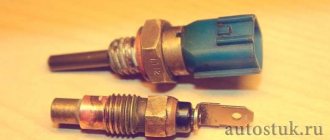
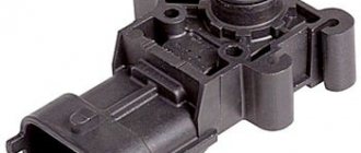
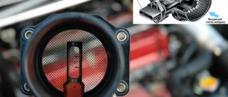
Where is it located and what does it look like?
If it is necessary to replace a faulty device, the consumer needs to know where the controller is located. It is located in the car distributor and is made in the body in the form of a small cylindrical element. To gain access to the device, it is necessary to disassemble the distribution unit and remove the cover, slider and other parts of the mechanism. On the outside of the distributor, a connector with wiring is connected to the Hall controller.
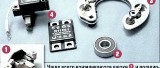
Device
The optical camshaft position regulator is designed as follows:
- 1 - permanent magnetic device;
- 2 — blade of the rotor mechanism;
- 3 - magnetic circuits;
- 4 - plastic case, which contains all elements of the device;
- 5 - board;
- 6 - contact pins.
Hall controller adaption diagram
The device is equipped with three contacts:
- the first is used to connect to ground, that is, the car body;
- the second is necessary to connect positive voltage, the operating parameter of which is approximately 6 volts;
- the third contact is intended to send an impulse from it to the switching device.
Operating principle of the device
This is a device that records magnetic flux intensity. In fact, this is a sensor for the presence of a magnetic field. Sensors are available in both digital and analogue types. The first type is based on measuring the field induction and the formation of the corresponding voltage, and the second type responds to changes in the polarity of the magnetic flux.
The operating principle of the Hall sensor is based on the galvanomagnetic phenomenon. This phenomenon is the result of a magnetic field interacting with a semiconductor that is connected to electrical energy, changing its electrical properties. The Hall effect manifests itself if a transverse voltage is generated in a semiconductor located in a magnetic flux when current flows through it. In this case, the direction of the charge is perpendicular to the field direction vector. The emerging phenomenon is explained by the fact that mobile electrons or holes in the magnetic flux are affected by the Lorentz force, leading to their deflection.
In a simple example, the Hall effect is represented as follows. In a semiconductor, under the influence of the Lorentz force, charge carriers move in different directions, corresponding to their sign. On one side of the semiconductor, electrons accumulate, a negative charge, and on the other side, where the electrons moved, a positive charge. Between these sides, due to the difference in charges, an electric flow is formed, which prevents the movement of charges under the influence of the Lorentz force. When the moment of equality of the Lorentz forces and the magnetic field comes, the semiconductor goes into a state of equilibrium.
According to their type, sensors can be produced with a different number of contact pins and are:
- two-pin;
- three-pin.
Since the signal level at the sensor outputs is low, an operational amplifier is connected to its outputs. By adding a trigger, a simple device is obtained that is triggered at a certain value of the magnetic field and type of conductivity. In digital electronics, sensors complemented by logic elements are divided into three groups:
Unipolar. The device registers only changes in one value of charge carriers, hole or electron conductivity.- Bipolar. The sensor reacts to both types of charge carriers, but performs opposite actions in relation to them. For example, when recording electronic conductivity, the device connected to it starts working, and when recording hole conductivity, it turns off.
- Unipolar. They simply record the appearance of conductivity and do not depend on its type.
A sensor that uses three terminals contains an open-collector transistor in its housing, since the current of the device is low and it is used in conjunction with a signal amplifier.
What malfunctions can there be?
Symptoms of Hall controller problems:
- There is a sharp increase in fuel consumption in the system. This is due to the fact that the injection of the combustible mixture into the power unit occurs more than once per cranking cycle.
- The car's engine began to function less stable. The vehicle jerks while driving, and engine power may drop sharply. Sometimes it is not possible to increase the speed of the car by more than 60 km/h. While driving, the power unit may randomly stall.
- Sometimes a Hall sensor failure causes the transmission lever to lock. It is impossible to change the gearbox speed; this feature is typical for new foreign cars. To solve the problem, you need to restart the power unit.
- A malfunction may manifest itself in the form of a lack of spark to ignite the combustible mixture. Because of this, starting the car engine will be impossible.
- There may be malfunctions in the functioning of the self-diagnosis system. For example, an engine check indicator appears on the control panel if the unit is idling. When the engine speed increases, the error message disappears from the dashboard.
The Auto-Moto channel talked about signs of a faulty regulator, as well as other elements of the ignition system in a car.
If the Hall controller itself is intact and working, then the malfunction may be due to the following reasons:
- There is dirt or other foreign objects on the device body.
- The signal cable through which the controller is connected is damaged or broken.
- Moisture has entered the block for connecting the Hall sensor to the on-board network. The problem can be solved by drying the connector.
- There is a short circuit between the signal conductor and the vehicle body or electrical network. To determine the malfunction, you need to ring the device.
- The shielding component on the wiring harness has been damaged. Individual cables may break.
- The problem may be damage to the conductors intended to power the Hall controller.
- The polarity was reversed when connecting the device. Because of this, the sensor does not function correctly or does not work at all.
- Malfunctions in the functioning of the high-voltage circuit of the ignition system.
- Problems in the functioning of the vehicle control module.
- When installing the controller, the backlash between the sensor itself and the magnetic conductive plate was incorrectly set.
- The problem may lie in the increased amplitude of the end action of the camshaft gear. Detailed diagnostics of the circuit is required.
Dmitry Maznitsyn in the video talked about the reasons for the regulator malfunction and gave recommendations for eliminating them.
Sensor check
There are several ways to diagnose a controller. The most accurate option that will allow you to obtain an oscillogram is to use special equipment. An oscilloscope will not only determine the state of the controller, but will also make it clear that the device will soon fail. Not every electrician has such equipment, so simpler, but no less effective options are discussed below.
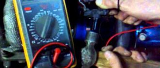
Diagnostics with a multimeter
Before testing, the device must be set to DC measurement mode, the operating range should be 20 volts. You will also need two metal pins. Before carrying out diagnostics, the rubber cover is removed from the device connector.
The preliminary check procedure to determine that the necessary signals are supplied to the Hall controller is performed as follows:
- The main armored wire is disconnected from the distribution unit. It must be connected to the vehicle ground to prevent accidental discharge. Because this will cause the power unit to start during diagnosis.
- Then the ignition system is activated.
- The connector is disconnected from the distribution mechanism.
- The tester is set to DC mode with a range of 20 volts.
- The negative contact of the multimeter is connected to the car body, you can choose any place. The positive output of the tester will be used to measure the operating voltage parameter.
- The connector connected to the distribution unit is equipped with three contacts - red, green and white, but the colors of the conductors may be different. At the first output the voltage value should be 11.37 volts or about 12 V, at the second output it should also be around this value. And on the last conductor the operating parameter should be 0 volts.
Next stage of diagnosis:
- Take two metal pins, you can use nails. One of them is installed in the middle contact of the block (usually green), and the other is connected to ground. Its color is usually white. The connector itself is then connected back to the switchgear. The pins are used as current conductors. There are no open contacts on the back of the connector, so to check the cables themselves you will have to expose them, and this is not recommended.
- The ignition is then activated. The positive contact of the tester must be connected to the middle output pin on the connector, and the negative contact to the white conductor. The voltage is measured. If the Hall controller is working, then the resulting value should be about 11.2 volts.
- Then you need to rotate the crankshaft of the power unit and at the same time check the indicators that the tester gives. If the values decrease to 0.02 volts during cranking and then increase to 11.8 V, then this is normal. This is how it should be in the lower and upper limits of measurements. You can turn off the tester.
The Hall controller is considered working if, when cranking the crankshaft, the upper measurement limit is not lower than 9 volts, and the lower limit is not higher than 0.4 V.
The “Autoelectrics HF” channel showed in detail the procedure for diagnosing a sensor using a tester and talked about the main features of this process.
Resistance check
To diagnose this parameter, you will need a simple device consisting of a 1 kOhm resistor element, a diode light bulb, and flexible cables. A resistor must be connected to the leg of the light source; soldering is used for reliable fixation. Two conductors of the required length are connected to this part; it is important that they are not short.
The verification principle looks like this:
- The distribution mechanism cover is being dismantled. The distributor itself is disconnected from the contacts, as well as the block with wires.
- Diagnostics of the health of the electrical circuit is performed. To do this, the tester must be connected to the first and third terminals, and then activate the ignition. If all conductors are intact, then the voltage on the multimeter display will be from 10 to 12 volts.
- Then, in the same way, the assembled device is connected to the same outputs. When the polarity is correct, the diode light will light up; if not, then the cables must be swapped.
- Then the conductor connected to the first output remains untouched. And the end of the third terminal switches to the second. The camshaft is being rotated. This can be done by hand or using a starter mechanism.
- If during these actions the light source begins to blink, then the controller is working correctly and does not need to be replaced.
The Altevaa TV channel talked about a way to check the sensor using a regular light bulb using the example of a Volkswagen car.
Creating a Hall Controller Simulation
This option for diagnosing the Hall sensor is considered the fastest, but its implementation is possible if there is power in the ignition system and there is no spark.
The three-pin connector is disconnected from the distribution mechanism. The ignition in the car is activated and, using a piece of conductor, contacts numbered 2 and 3 are closed, these are the signal outputs and pin. If, as a result of the connection, a spark is formed on the central cable, this indicates a breakdown of the Hall controller. When performing the task, the high-voltage conductor must be kept near the ground of the car.
DH device
We have already noted that in a car, sensors operating on a principle invented almost a century and a half ago can be used for a variety of purposes, but they are a mandatory component only in the ignition system.
Therefore, it makes sense to describe the design of a Hall sensor of this particular type. It consists of:
- a microcircuit that captures voltage changes on the plate;
- permanent magnet;
- plastic case;
- rotor blades;
- contact group;
- magnetic cores.
Despite the relatively large number of components, such a sensor has a number of undeniable advantages:
- thanks to the miniaturization of modern microcircuits, it has compact dimensions;
- in electrical engineering terms, the electrical signal generated by the sensor has a clearly defined rectangular shape - when turned on, it almost instantly takes on a certain stable value without smooth ascents and descents, which is extremely important for digital devices such as a controller;
- in a sensor that measures crankshaft rotation speed, the dynamics of the response frequency (as a result of changes in engine speed) does not lead to a mismatch in the measurement moment.
However, DH also has disadvantages. The main one is the low sensitivity of the device, which can be significantly influenced by external electromagnetic interference generated in the vehicle’s on-board electrical circuit as a result of the operation of a large number of electronic/electrical devices and instruments.
The higher cost of the Hall sensor compared to analogues of the magnetoelectric type is offset by the simplicity of large-scale production. As for reliability, the vulnerability of the DC lies in its poor protection from electrical interference, but it lacks or minimizes mechanical components that are subject to rapid wear.
Trouble-shooting
The repair is considered using a Volkswagen car as an example.
To restore functionality, the sensor can be repaired:
- To restore controller operation, the logic component must be replaced. To do this, you need to purchase the S441A device in advance.
- In the central part of the sensor body, as shown in the photo, a small hole is drilled using a drill. This will require a high-quality drill, since there is a metal frame inside the controller, behind the plastic part.
- Using a utility knife, you need to cut off each conductor. Then grooves are laid from the hole made using a file to the remaining cables.
- The measuring device itself is mounted in the housing window. A magnet is used for diagnostics. If you attach this element to the contacts to which a device consisting of a diode light bulb and a resistor is previously connected. This device was used for diagnostics. As a result of the test, the lamp should light up. If this does not happen, then you need to check the polarity.
- Then the leads are routed along the grooves of the housing. In the window itself, you must leave the conductors for the connecting block of the new controller. The elements are soldered.
- At the final stage, the completed actions are checked. A tester is used for this. It is necessary to visually verify the integrity of all contacts. If the device is working, then the mechanism is sealed using glue or another composition, but not plastic. This material can become deformed when working at elevated temperatures.
- The controller is being assembled, all actions are carried out in the reverse order.
Connecting contacts to element S441A
Place for drilling the body of the device
Installing the device in a distribution node
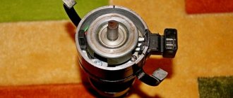
The design of the contactless ignition system and its operating principle
A non-contact ignition device is essentially not very different from a contact ignition. The only cardinal difference between the electronic system is the absence of a distributor, as well as the presence in it of a transistor switch unit and a pulse sensor.
When the motor is running, the distribution sensor generates pulses that are sent to the transistor switch. Then, using this switch, pulses are created, but in the primary winding of the existing ignition coil. When the current is interrupted, a high voltage inductive current appears directly in the secondary winding of our ignition coil. After this, the current from the electrical contact of the distributor flows in the required sequence to the high voltage wires and then to the spark plugs.
How to replace the sensor yourself?
To change the controller, you need to do this:
- The terminal clamps are disconnected from the car battery.
- The distribution mechanism is being dismantled. The block with conductors is disconnected from the device, the bolts securing the unit are unscrewed.
- The distributor cap is being removed. Depending on the distributor model, it can be fixed with bolts or special clamps. The fastening elements are unscrewed and dismantled.
- After removal, it is important to align the mark of the gas distribution device with the mark on the crankshaft of the power unit. It is also necessary to remember the position of the distribution unit. It is recommended to make a corresponding mark before removal.
- The housing fastening elements are unscrewed using a wrench. The clamps are dismantled if they are installed on the mechanism.
- The shaft is removed from the distribution unit.
- The clamps with terminals are disconnected from the Hall controller.
- The sensor is removed from the mounting location. To carry out the task, the device must be pulled towards you and carefully removed. The sensor is dismantled through the hole that appears.
- A new controller is taken and installed in place of the old one. The installation procedure is performed in reverse order.
Video “Consequences of incorrect installation of the Hall sensor”
User Uncle Sasha explained what could result from incorrect installation of the device and gave recommendations on how to fix this problem.
Do you have any questions? Specialists and readers of the AUTODVIG website will help you ask a question
Was this article helpful?
Thank you for your opinion!
The article was useful. Please share the information with your friends.
Yes (100.00%)
No
X
Please write what is wrong and leave recommendations on the article
Cancel reply
Rate this article: ( 2 votes, average: 5.00 out of 5)
Discuss the article: