Operating principle of the ABS sensor
Any diagnostic measure will not be effective if the driver does not have an idea of the operating principles of the unit or element of the system being examined. Therefore, before the stage involving surgical intervention in the operation of this device, first of all, you should study the principle of its operation.
What is an ABS sensor?
Let's start with the fact that this simple device can be found on each of the 4 hubs of the car. The solenoid is located in its sealed plastic housing.
Another important element of the sensor is the so-called pulse ring. The inner side of the ring is made in the form of gear cutting. It is mounted on the back of the brake disc and rotates with the car wheel. There is a sensor at the end of the solenoid core.
The fundamental features of the operation of this system are based on reading the electrical signal coming from the throttle directly to the reading device of the control unit. So, as soon as a certain torque is transmitted to the wheel, a magnetic field begins to arise inside the electromagnet, the value of which increases in proportion to the increase in the rotation speed of the pulse ring.
As soon as the rotation of the wheel reaches the minimum number of revolutions, the pulse signal from the presented sensor begins to enter the processor device. The pulse nature of the signal occurs due to the toothed rim of the pulse ring.
The subsequent operation of the valve body of the ABS system depends on the frequency of the signal registered in the receiving device. The executive elements of the hydraulic brake force distributor are solenoids, a hydraulic pump and valve mechanisms.
Depending on the intensity of the signal entering the valve body, valve mechanisms controlled by solenoids come into operation. In the event that a wheel locks, the hydraulic unit, taking into account the corresponding signal, reduces the pressure in this brake circuit.
At this moment, the hydraulic pump comes into operation, pumping the brake fluid back into the GTZ reservoir through the open bypass valve. As soon as the driver reduces the force on the pedal, the bypass valve closes, and the pump, in turn, stops working.
At this moment, the main valve opens and the pressure in this brake circuit returns to normal.
The presented modification of the ABS peripheral element is the most common and is used on most domestic and foreign cars.
Due to the relative simplicity of this design, the system elements are highly resistant to mechanical wear and have good performance.
If a part fails, it is not so expensive to carry out the manipulations described below. It's easier to buy and replace the sensor with a new one.
Restoring wiring integrity
There should not be any particular problems with the issue of replacing or restoring the sensor connection wiring. For these purposes, any two-core cable of a similar cross-section or two pieces of field wire of the required length will be suitable. In your work, you must use only the soldering method and carefully insulate the joints with heat-shrinkable tubing or electrical tape. Special attention should be paid to the rubber seals that are located at the points where the wiring is attached to the body parts - if the cord is completely replaced, they should be placed in the same place.
When replacing the wire, install rubber seals at the points of its attachment to the body
Attention! When connecting the wiring to the ABS sensor, you need to take into account that the device has polarity. The car's operating instructions indicate the color coding of the wires - the connector of the part has exactly the same designations.
The process of repairing the ABS sensor wiring is described in more detail in the video presented.
Video: How to repair a section of wire on a Chevrolet Aveo
Repairing an ABS sensor is a very time-consuming and troublesome task. If you are not persistent and patient, or simply do not have free time, you are unlikely to take on the business. Well, those who are used to solving all problems on their own and do not want to spend extra money can now easily do this work on their own.
Sensor types
There are two types of sensors on cars:
- passive sensor built on the basis of a coil;
- active sensor that uses the Hall effect.
The passive sensor turns on after the start of movement and reads data from the toothed pulse ring. The passage of a tooth past the device causes the generation of a current pulse, which is read by the control unit. The sensors start working at speeds above 5 km/h and do not respond to contamination.
The active sensor consists of electronic components and a permanent magnet, which is mounted on the hub. When the magnet rotates in the device, a potential difference arises, which is formed into a microcircuit control signal. The information is then sent to the block. Sensors of this design are rare and cannot be repaired.
Passive
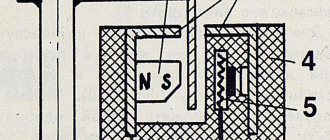
They are distinguished by a simple operating system, but are quite reliable and have a long validity period. Does not require a power connection. An inductive sensor is essentially an induction coil made of copper wire, in the middle of which there is a stationary magnet with a metal core.
The meter is located with the core to the pulse rotor in the form of a wheel with teeth. There is a certain gap between them. The rotor teeth are rectangular in shape. The opening between them is equal to or slightly larger than the width of the tooth.
While the vehicle is in motion as the rotor teeth pass near the core, the magnetic field penetrating the coil is constantly changing, forming an alternating current in the coil. The frequency and amplitude of the current are directly dependent on the speed of the wheel. Based on processing of this data, the control unit issues a command to the magnetic valves.
The disadvantages of passive sensors are:
- Relatively large dimensions;
- Poor accuracy of readings;
- They begin to function when the car picks up speed over 5 km/h;
- Triggered by minimal wheel rotation.
Due to frequent errors, they are installed extremely rarely on modern cars.
Magnetoresistive
The work is based on the property of ferromagnetic materials to change electrical resistance when exposed to a constant magnetic field.
The part of the sensor that controls changes is made of two or four layers of iron-nickel plates with conductors applied to them. Part of the element is installed in an integrated circuit that reads changes in resistance and generates a control signal.
The impulse rotor, which is a magnetized plastic ring in places, is rigidly fixed to the wheel hub. During operation, the magnetized sections of the rotor change the environment in the plates of the sensitive element, which is recorded by the circuit. Its output produces pulsed digital signals that enter the control unit.
This type of device controls the speed, direction of rotation of the wheels and the moment they come to a complete stop.
Magnetoresistive sensors record changes in the rotation of vehicle wheels with great accuracy, increasing the efficiency of safety systems.
Based on Hall element
This type of ABS sensor operates based on the Hall effect. In a flat conductor placed in a magnetic field, a transverse potential difference is formed.
Hall effect - the appearance of a transverse potential difference when a conductor with direct current is placed in a magnetic field
This conductor is a square-shaped metal plate placed in a microcircuit that includes a Hall integrated circuit and a control electronic system. The sensor is located on the opposite side of the pulse rotor and has the form of a metal wheel with teeth or a plastic ring, magnetized in places, rigidly fixed to the wheel hub.
This is interesting: What to do if the cigarette lighter in the car does not work
The Hall circuit continuously produces signal bursts of a certain frequency. At rest, the signal frequency is reduced to a minimum or dies out completely. During movement, magnetized areas or rotor teeth passing by the sensing element cause changes in the current in the sensor, which are recorded by the tracking circuit. Based on the received data, an output signal is generated and sent to the control unit.
Sensors of this type measure speed from the beginning of the vehicle’s movement and are distinguished by the accuracy of measurements and the reliability of their functions.
Signs of a malfunctioning ABS sensor
The first sign of an ABS malfunction is a lit indicator on the instrument panel that does not go out for more than 6 seconds after turning on the ignition, or does not turn on when driving. A system breakdown is detected when the vehicle is moving at a speed of more than 25 km/h. There are quite a few problems that can happen with the anti-lock braking system, but the most common ones include the following:
- ABS sensor wire is broken or the controller unit is damaged. In this case, an error is displayed on the instrument panel, the system is turned off, and signals about changes in angular velocities are not given.
- The wheel sensor of the system has failed. When turned on, the system performs self-diagnosis and detects an error, but continues to function. The cause of the breakdown may be oxidation of the contacts, poor power supply to the sensor and a short circuit to ground.
- Receipt from an additional device of information about different angular speeds of wheels at different tire pressures or different tread patterns, when the wheels brake differently.
- Mechanical failure of elements - hub bearings, play and fracture of the rotor on the wheel sensor. In case of such failures, the system does not start. This also includes ABS pump failure.
The most vulnerable element of the system is the wheel sensor, which is located next to the rotating hub and axle shaft. Exposure to dirt and play in the hub bearings can damage the device, completely blocking the operation of the ABS. Along with the indicator signal on the instrument panel, the following signs indicate a sensor failure:
- The on-board computer displays an ABS system error code.
- There is no characteristic vibration or sound when pressing the brake pedal.
- The wheels lock during emergency braking.
- Appearance of the parking brake signal when it is disabled.
How to recognize that the ABS sensor is no longer performing its functions?
On older cars, a malfunction of the ABS sensor can lead to the most unpleasant consequences. If the wire breaks, the voltage may not reach the computer, just like when the wheel is locked. Therefore, a simple computer perceives this situation in such a way that one of the wheels is blocked. Ultimately, ABS begins to unlock one wheel during braking, which can completely disable the braking system, and in case of an emergency stop, provoke a complete loss of control, even causing the car to overturn. Signs that the ABS sensor is faulty are:
- after inadequate operation of the system, the inscription “ABS” appears on the dashboard, the module stops working;
- on modern cars, after starting the engine, the ABS light does not go out, and the system stops working;
- during weak braking, the pedal vibrates, the brake force distribution system turns on;
- auxiliary brake systems, amplifiers and balancing devices are constantly operating;
- the on-board computer displays a number of problems that are related to the operation of the anti-lock braking system;
- When connected to a diagnostic computer, an error code for the anti-wheel lock system sensor is read.
You can independently determine whether the sensor is faulty if the ABS light is constantly displayed on the dashboard. This is the main indicator that some sensor has stopped functioning and the system simply does not work. In this case, the first task of the motorist will be to check the integrity of the wires to the sensors. These wires often break due to stones being thrown into the hub area or other objects that cut the wire. Therefore, such a problem is not uncommon; almost all owners of cars with this module know it.
What is the danger of such a situation?
The safety of moving a car lies in complete control over it, under any conditions. While the wheels rotate along the braking distance, the driver directs the car in the desired direction with his own hands. If the car does not have time to stop before the obstacle, you can go around it. But modern brakes are so powerful that the wheels lock on even the slightest slippery surface, and sometimes even on dry asphalt. In Moscow, the speed limit on the Moscow Ring Road is up to 110 km/h. Under such conditions, even the most advanced tire will slip when braking.
What should automakers do? Reduce braking force? It is unacceptable.
In the 70s of the last century, a solution was found: the anti-lock braking system (ABS).
The technology allows you to maintain vehicle controllability during braking. The wheels are not blocked, therefore, the car obediently follows the steering.
How to diagnose the ABS system
Diagnostic measures involving checking the ABS system are usually carried out using special equipment. One of them is the so-called diagnostic adapter. To connect it, the manufacturer provides a special diagnostic connector.
The system test begins when the ignition is turned on. The essence of such a check is that using the adapter it is possible to identify the presence of a particular system error. Each error is assigned a specific code, which allows us to judge the malfunction of a specific node or element of the system.
However, it is worth noting that in most cases, budget segment diagnostic adapters do not scan the entire system, but only the engine. Therefore, we recommend using a scanner with comprehensive diagnostics.
For example, we can include the Korean-made model Scan Tool Pro Black Edition. Having a 32-bit chip on board, this scanner is capable of diagnosing not only the engine, but also other components of the car (gearbox, transmission, ABS auxiliary systems, etc.) and at the same time has a fairly affordable price.
This multi-brand scanner is compatible with most cars from 1993 onwards; it shows the operation of all available sensors in real time, the car’s VIN code, its mileage, ECU version, etc.
The device is capable of measuring the stability of various systems over certain periods of time and storing the obtained data in any device based on iOS, Android or Windows.
This is interesting
: How to check the high pressure sensor G65 of the air conditioning system
Diagnostics and preventive measures to judge the performance of system elements are carried out in specialized service centers. However, this task can be handled in a garage environment.
So, all that is required to diagnose the ABS sensor is a minimum set of equipment, including: a soldering iron, a multimeter, heat shrink and repair connectors.
The verification algorithm consists of the following stages:
- wheel jacking;
- dismantling the control unit and controller outputs;
- connecting repair connectors to sensors;
- measuring resistance with a multimeter
If the sensor has not failed, the ohmmeter will show a resistance of about 1 kOhm. This value corresponds to the performance of the sensor at rest. As the wheel rotates, the readings should change. This will indicate its serviceability. If no changes are observed in the readings, the sensor has failed.
It is worth noting that due to various modifications of sensors, their operating parameters may vary. Therefore, before condemning a sensor, you must first become familiar with its operating range and only then draw conclusions about its serviceability.
For your information
: How to resolve error P0171 (air-fuel mixture too lean)
In addition, if malfunctions occur in the ABS, it is necessary to ensure that there is no damage to the underwater wires. If a break is detected, the wires should be “soldered”.
Do not also forget that the repair pins must be connected in accordance with the polarity. Despite the fact that in most cases, if the connection is incorrect, protection is triggered, this should not be done. To make the task easier, it is best to pre-mark the corresponding wires with a marker or insulating tape.
This is interesting: Signs and causes of car alternator malfunction
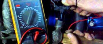
Tester (multimeter)
In addition to the measuring device, you will need a description of the functionality of this model. Sequence of work performed:
- The car is placed on a platform with a smooth, uniform surface, its position is fixed.
- The wheel is dismantled for free access to the sensor.
- The plug used for connection is disconnected from the general wiring and cleaned of dirt. The rear wheel connectors are located in the rear compartment. To ensure unobstructed access to them, you need to remove the rear seat cushion and move the carpet with soundproofing mats.
- Conduct a visual inspection of the connecting wires for abrasions, breaks and damage to the insulation.
- The multimeter is set to ohmmeter mode.
- The sensor contacts are connected to the probes of the device and the resistance is measured. The standard readings can be found in the instructions. If there is no reference book, then readings from 0.5 to 2 kOhm are taken as the norm.
- The wiring harness must be checked to exclude the possibility of a short circuit.
- To confirm the functionality of the sensor, spin the wheel and monitor the data from the device. The resistance reading changes as the rotation speed increases or decreases.
- Switch the device to voltmeter mode.
- When the wheel moves at a speed of 1 rpm, the voltage should be 0.25-0.5 V. As the rotation speed increases, the voltage should increase.
- Observing the stages, check the remaining sensors.
It is important! The design and resistance values of the sensors on the front and rear axles are different.
A resistance of 0.5 to 2 kOhm at the ABS sensor terminals is considered optimal
Based on the measured resistance values, the performance of the sensors is determined:
- The indicator is reduced compared to the norm - the sensor is faulty;
- Resistance tends to or corresponds to zero - interturn short circuit in the induction coil;
- Changing the resistance data when bending the wiring harness - damage to the wire cores;
- The resistance tends to infinity - a wire break in the harness or induction coil of the sensor.
It is important! If, after checking the functions of all sensors, the resistance value of any of them differs significantly, this sensor is faulty.
Before checking the wiring for integrity, you need to find out the pinout of the control module plug. After that:
- Open the connections between the sensors and the control unit;
- According to the pinout, all wire harnesses ring in turn.
Oscilloscope
Among other things, you can use an oscilloscope to diagnose interruptions in the operation of the ABS sensor. It is worth noting that the use of the presented device requires certain skills. If you are an avid radio amateur, it will not be difficult for you to resort to such diagnostics. But for the average person, this can cause a number of difficulties. Let's start with the fact that this device will not cost you cheap.
Among other things, its use is mostly justified in the context of a specialized service. However, if by some miracle you have this strange device lying around in your garage, it will be a good help for carrying out various diagnostic measures.
An oscilloscope creates a visualization of the electrical signal. The amplitude and frequency of the signal are displayed on a special screen, which gives a clear picture of the operation of a particular element of the system.
In this case, the principle of checking the serviceability of the ABS sensor will be based on a comparative analysis of the results obtained. So, the entire procedure at the initial stage is similar to that carried out previously with a multimeter, only instead of a tester, an oscilloscope should be connected to the sensor terminals.
On this topic
: 5 reasons why the car pulls to the side
The diagnostic procedure is as follows:
- rotate the suspended wheel at a constant frequency of about 2-3 rps;
- record the value of the oscillation amplitude on the oscilloscope display.
As soon as the readings from one sensor are taken, it is necessary to carry out the same actions with the sensor installed on the opposite side of the same axis.
The results obtained should be compared and the appropriate conclusions drawn:
- with relatively equal readings, the sensors can be considered serviceable;
- the absence of a step-like phenomenon when setting a smaller sinusoid signal indicates the operability of the sensor;
- maintaining a stable amplitude with a peak value not exceeding 0.5 V at the specified speed - the sensor serves faithfully.
A good alternative to an expensive device can be a special application with which you can carry out all diagnostic activities using an ordinary laptop.
Without devices
Correct operation of the sensor can be determined by the presence of a magnetic field. For this purpose, any object made of steel is applied to the sensor body. When the ignition is turned on, it should be attracted.
In addition, it is necessary to inspect the sensor housing for its integrity. There should be no abrasions, insulation breaks, or oxides on the wiring. The sensor connector must be clean and the contacts must not be oxidized.
It is important! Dirt and oxides on the plug contacts can cause signal transmission distortion.
Analysis of diagnostic results
The problem with the ABS function does not always lie in the sensors. The culprits of system failure may also be the wires connecting the elements to the control unit. That is why it is necessary to carry out 3 measurements and draw the following conclusions based on the results:
- If the resistance of the ABS sensor tends to zero or, conversely, the device shows an infinity symbol, then there is a malfunction of the element itself. Another option is a violation of the insulation or a break in the section of conductors from the connector to the sensor.
- The tester shows that the resistance is within normal limits, but when the brake disc rotates, its value remains constant. There are two versions here: severe contamination of the gear ring (as an option - destruction) and, again, failure of the sensor.
- The absence of voltage in the supply line indicates a break in the electrical circuit coming from the controller.
In the first case, it is necessary to remove the device from the hub and inspect the wires for fractures, breaks or short circuits. To be sure, measure the resistance again, while moving the conductors. If the result is negative, buy and install a new part.
If the resistance remains the same, get to the gear ring, clean it thoroughly and inspect it. If you find mechanical damage, it is better to replace the spare part.
Advice. Sometimes unscrupulous or ignorant auto mechanics damage the ring when repairing the suspension, or even throw it away completely. When picking up your car from a mechanic, always check that this important part is present.
In the case when there is no voltage in the controller circuit, you should ring this section of the wiring. How to do it:
- Find out where the electronic control unit for the hydraulic valves is located. For example, in a Chevrolet Aveo it is located behind the brake fluid reservoir, and in a Renault Megane it is located on the side of the alternator drive belt.
- Remove the block from the ECU and clean the contacts. Find the pinout of the wires or track them by color.
- Place a shorting jumper on the block located near the wheel. Test the circuit with an ohmmeter or a regular light bulb with a battery.
This is interesting: Decoding error p1602 - controller voltage interruption
The easiest way to find the ECU if there is no documentation for the car is to follow the brake pipes leading to the hydraulic unit. The latter stands next to the controller or is connected to it by a bundle of wires.
If an open circuit is detected, you will have to look for the defect along the entire line in order to eliminate it. The work is quite complex, so it should be entrusted to an experienced auto electrician.
How to resolve detected faults
Once the diagnostic measures are successful and the problem is found, it becomes necessary to eliminate the faulty element of the system. When it comes to the ABS sensor or impulse ring, there is no need to talk about restoring their functionality.
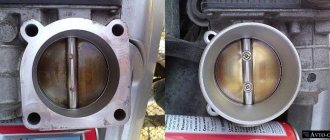
In this case, they usually need to be replaced. An exception may be the case when the working surface of the sensor has simply become dirty during long-term use. To do this, it will be enough to clean it of oxides and dirt particles. It is advisable to use ordinary soapy water as cleaning agents. The use of chemicals is highly undesirable.
How to fix problems
After checking with instruments and identifying the faulty unit, you can begin repairs. Some owners repair the sensors by replacing the wiring harness or rewinding the coil.
Sensor failure
A faulty passive type sensor can be repaired yourself:
- Remove the sensor from the hub. The fastening bolt often becomes sour, so you should unscrew it carefully. For removal it is allowed to use WD40 type fluid.
- Remove the protective coil housing. Removal is done with a file. The cut should be done extremely carefully so as not to damage the housing and winding.
- Remove the protective film from the winding by prying it off with a sharp knife.
- Carefully unwind the wire from the spool. During the removal process, the version of a conductor break is confirmed. As a result, you will be left with an empty ferrite core, resembling a spool of thread in shape.
- Wind a new winding. Copper wire from the coils of common relays of the RES-8 type can be used as a conductor. Winding can be done using a drill with smooth speed control. Be careful as breaking the wire will return you to the start. It is recommended to wind the conductor to the top level of the coil.
- Check resistance. Most coils have a value in the range of 0.9-1.2 kOhm. To clarify, it is recommended to measure the parameter on a known-good sensor located on the opposite side of the axis. The resistance is adjusted by unwinding the excess wire. If the reading is low, you will need to use another wire or re-wind. Secure the wire from unraveling with tape or other adhesive tape.
- Solder the wires to the coil terminals that serve as a connection between the winding and the harness. For outputs, it is recommended to use multi-core insulated cable, which has increased strength.
- Install the coil into the old housing. If it received significant damage when disassembling the device, then the coil is filled with epoxy resin. To do this, the part is located in a metal container of a suitable size, for example, a capacitor housing. The air gap between the coil and the glass is carefully filled with resin. When pouring, it is advisable to avoid large air voids. After the resin has completely hardened, the body is removed.
- Reinstall the sensor mount, securing it with epoxy resin. Conduct a visual inspection of the product for cracks and voids in the insulation. Detected defects are filled with resin.
- Place the repaired sensor in its original place and check the functionality of the ABS system. When installing the device, it may be necessary to modify the resulting body, which is done with a file and sandpaper. The field installed sensor should have a gap between the coil and the toothed ring within 0.9-1.1 mm. When reducing the gap, it is recommended to bring it up to standard by installing gaskets.
It is necessary to drive the car for some time, checking the operation of the brakes at different speeds. There are cases when the ABS spontaneously activates at certain wheel speeds - usually just before stopping. Then you will need to search for the gap, adjusting it with shims or sharpening the sensor body.
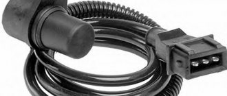
Another repair option is to install a modified crankshaft position sensor from domestic cars:
- Remove the “original” sensor and modify the body of the “donor” part. Most often, this role is played by the DPKV from the ZMZ-406 engine, which has a resistance within 800 Ohms. When modifying, you should strive to ensure a parallel arrangement of the core with the wound coil and the toothed ring mounted on the axis. The gap between the sensor and the ring should be within 0.2-0.3 mm.
- Test the operation of the device. On some Japanese-made cars, the ABS lamp may turn on periodically. The situation is corrected by changing the connection of the harness contacts.
Both options for repairing the sensor require perseverance and the ability to work with various tools from the owner. If the car user doubts his abilities, it is recommended to purchase a new device or find the product at a car dismantling site.
Wiring problem
If the problem of sensor loss of functionality lies in the wiring, then it can be replaced:
- Unscrew the sensor mount to the wheel hub.
- Disconnect the wire plug.
- Remove the sensor along with the wire. This will require removing the mounting brackets installed on the wiring.
- Measure the installation distances of the brackets. It is recommended to draw a diagram and photograph the factory location of the fasteners.
- Cut the sensor from the wire, leaving some extra length for soldering.
- Check the integrity of the remaining cable on the sensor. If the section is intact, then you can begin installing a new wiring segment.
- Remove all protective covers and fastenings from the old cable.
- Select a wire with a suitable outer diameter and cross-section.
- Install the previously removed protection and fastening elements onto the new harness. To facilitate assembly, it is recommended to use a soap solution.
- Solder the sensor and plug into place.
- Carefully isolate the joint. The accuracy of operation and service life of the repaired part depend on the tightness of the connection.
- Reinstall the sensor, check the functionality of the ABS system, and make sure there are no errors during operation.
Sources
- https://AutoVogdenie.ru/kak-proverit-datchik-abs.html
- https://avtozam.com/elektronika/sensor/kak-proverit-datchik-abs/
- https://carnovato.ru/proverka-datchika-abs/
- https://voditelauto.ru/datchik-abs/
- https://osensorax.ru/posiciya/kak-proverit-datchik-abs
- https://autochainik.ru/kak-proverit-datchik-abs-testerom.html
[collapse]
DIY sensor repair
After diagnostics and detection of a faulty element, the device must be dismantled for further repairs. The process of removing it is similar to the first stage of replacing the ABS sensor and is not particularly difficult.
Attention! Elements may stick to the seat; It will take a lot of patience to remove them from their mounting socket. Professional craftsmen advise generously moistening the metal around the device with WD-40 liquid and carefully removing the sensor, slowly loosening it.
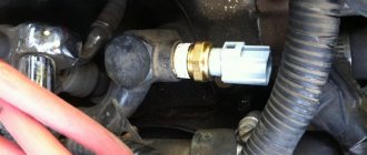
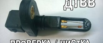
What a dismantled sensor looks like (photo)
How to fix: step-by-step instructions
Having finished dismantling the device, we proceed to repair work:
- We disassemble the sensor, cutting off with a hacksaw the part of it containing the measuring coil inside. Carefully saw through the body of the device in a circle, trying not to damage the fasteners.
Carefully separate the part with the fastener
This sensor element will be the subject of repair work.
In order to rewind the damaged wire, you need to remove the coil casing. The reel is completely cleared of old wire
The number of turns of the wire must be controlled by measuring the resistance
The copper winding of the coil must be carefully insulated
The capacitor shell can be used to fill the new coil housing.
This is what a new sensor housing made of epoxy glue looks like
The sensor mount can be glued to the part with quick-drying glue
The device is ready for installation on the seat
The repair of the sensor is completed, you can mount it on the hub, grinding the new housing with sandpaper for a better fit to the mounting socket. When installing a repaired device, be sure to comply with the following conditions:
- We position the sensor core parallel to the teeth of the response disk, making sure that it does not overlap two adjacent teeth.
- Leave a gap between the tooth and the core of 0.9–1.1 mm.
The final stage of repairing any of the ABS elements is to check the functionality of the system. We perform it by starting the car engine and making sure that the controller on the dashboard goes out 3-5 seconds after the start.
Attention! If the ABS indicator light periodically lights up when the car is moving after the sensor has been repaired, change the phasing of its connection wires.
Note that some sensors produced by the foreign auto industry can be disassembled without fundamentally compromising the integrity of the structure - the upper shell of the part can be removed by pre-heating it with a hair dryer or a blowtorch. An example of repairing such a device is presented in the video.