How to adjust the sensitivity of the steering wheel
When purchasing a car, almost every car owner experiences an irresistible (and quite justified) desire to adjust certain systems, which is called “for themselves.”
And not least on this list is adjusting the sensitivity of the steering wheel. This is quite logical, since a “sensitive” steering wheel is not only a comfortable ride, but also an appropriate degree of road safety (hereinafter referred to as road safety). So, this article is intended to answer the question: “How to adjust the steering sensitivity?”
We bring to the reader’s attention a small analogue of a guide to action for solving this problem:
- A clear understanding of the goals and objectives of sensitivity adjustment.
- Drawing up a list of operational characteristics that you would ultimately like to obtain (reaction to sudden rotation, size of backlash, etc.).
- Take it for a test drive with a service representative who is qualified to perform this type of adjustment.
Typology of basic systems
Lobdell system design
Based on a ratchet mechanism, the steering wheel's reach is adjusted without moving the steering column itself. However, this American development allows you to fix the steering wheel in only 7 positions; in addition, the tilt angle cannot be changed. Due to its archaic nature, such a system is found on very old foreign cars.
Telescopic steering wheel
makes it possible to move the steering wheel up and down a distance of up to 7.6 cm. Of course, the range is small, but greater accuracy of adjustment is provided, unlike the Lobdell system. This adjustment technique is still found on cars, especially on some Honda models.
Adjustable steering column
Now they are even available in basic versions of passenger cars. A rare exception to this rule is the Russian automobile industry: for example, on the Lada Granta, even in new versions, there is no height adjustment of the steering wheel; you can only change the tilt angle. But many Ford models have this option. Moreover, such cars are often equipped with mechanical locks and electric motors, which allows the system to remember the settings specified by the driver.
[custom_ads_shortcode2]
Varieties
Lada Priora hatchback Logbook Steering rack repair
There are two types - a classic column and an integrated one. The semi-integrated steering column belongs to the second type. The non-integrated one is a classic shaft with remote units and has a bore diameter of 33.9 mm. The integrated column has a large diameter due to the fact that all the bearings are inside the pipe.
There are two more types of fastening of steering control systems - threaded and threadless. The most common fastening is considered to be threaded, less often threadless is used. Such connections are most often used on bicycles.
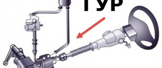
Design and principle of operation of the steering system
The purpose of the steering system is to control the rotation of the wheels; the direction of movement of the vehicle depends on it. Its main elements:
- drive (system of rods connected by hinges);
- steering mechanism (mechanical gearbox);
- additional amplifier (used in trucks and a number of new models of cars).
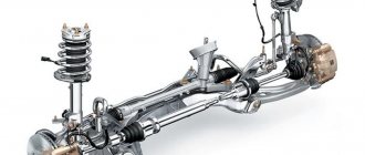
Car steering is a complex multi-component system
The steering mechanism converts the rotational movements made by the driver into translational movements of the drive, which transmits the energy of these movements to the wheels. At the same time, the driver does not need to exert much effort when turning the steering wheel, since its light effect is greatly amplified by the system. A working steering system allows you to accurately control the direction of movement and, if necessary, quickly change it, but its malfunctions can lead to loss of control.
Modern car models mainly use a rack and pinion steering system. The steering wheel, through the column shaft, is connected to a fixed gear, and that gear is connected to a movable rack, which is a rod element (steering linkage). The rack and pinion system is simpler and more reliable because it has fewer intermediate links and uses a worm gear less often.
Steering system designers try to find a compromise between convenience and safety. On the one hand, one turn of the steering wheel should be enough to control the wheels, on the other hand, excessive responsiveness of the wheels to steering movements can be dangerous in some situations. Therefore, racks with variable tooth pitch are often used, on which the gear ratio depends. They are located less frequently at the edges, and more often in the center.
An additional amplifier makes the system design more complex and advanced. It dampens shocks and vibrations, increasing ride comfort, and facilitates steering, helping the driver choose the optimal steering position. Power steering can be electromechanical or hydraulic (power steering). The latter option, consisting of a pump, reservoir, actuator and control valve, is more demanding to maintain, but it is the one installed on most models.
How to assemble a bicycle steering column
DIY steering rack repair
To ensure that the steering column is assembled correctly and the parts are not deformed, you need to use only professional tools. To install a threadless bicycle steering column:
- First you need to prepare the tools that you may need during the work process;
- The cups are installed in pre-lubricated places. One on top and one on bottom. The cups are pressed into the glass. If you don't have the necessary tool at hand, a hammer will do for this purpose. You just need to work with it carefully so as not to damage the parts;
- Place the crown on the fork and press the crown in a circle;
- install the bearing on the crown;
- put the glass on the fork and install the upper bearing;
- install the compression ring;
- install the steering stem;
- install steering wheel
Average prices for RK repairs
However, not all steering column faults can be eliminated on your own, so you need to know the prices for some types of repair work in car services in order to navigate if such a need arises.
The final cost of repair work will depend on the type of breakdown, as well as the make of the car, which is quite natural. On average, the cost (excluding the price of replacement parts) of some work in car service centers in Russia and the CIS countries is as follows:
- replacement of the steering column – from 1,500 rubles;
- steering column adjustment – from 1,000 rubles;
- diagnostics of the steering column - from 500 rubles;
- replacement of traction – from 500 rubles;
- replacement of tips - from 300 rubles.
- replacement of the lever – from 700 rubles.
Plug standards
What is a worm gear used for? Worm steering mechanism. Steering device
Bicycle forks have the following standards with mounting dimensions. A bicycle suspension fork is a part of a complex structure.
The main function of a bicycle fork is to hold the front wheel; thanks to the steering column and fork, rotation is carried out using the steering wheel, which allows you to adjust the direction of movement of the moving bicycle.
The main parts of a bicycle fork: legs, pants, dropouts, “gorilla” (Fig. 2).
The following types of forks are distinguished:
The more difficult it is, the more self-care it requires. More complex models such as elastomer and spring-oil forks require special technological professional care. If there is a need for repairs, it is better to contact a bicycle workshop.
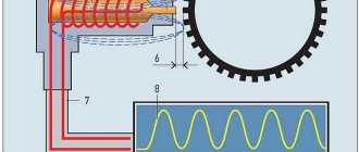
Backlash - steering
The steering play is checked using a model K-402 device.
They identify steering play, play in the tie rod joints, pivot joints of the steering axles, installation angles and balancing of the front wheels.
The amount of steering play exceeds the standard set by the manufacturer, rotation of the steering wheel is difficult, steering parts are damaged, loose or unpinned, and the hydraulic booster is faulty.
| Adjusting pneumatic wheel brakes.| L Adjusting the parking gear. |
How bad the steering play was.
What instruments determine steering play?
Before each trip to work, it is necessary to check the amount of steering play. Free play (play) of the steering wheel is allowed no more than 25 degrees.
During the first technical maintenance: check the action of the tension spring and, if necessary, adjust the free play of the clutch pedal; check the fastening of the gearbox, intermediate support of the propeller shaft, gearbox, axle shaft flanges and wheel drive covers, check the play of universal joints and splined joints of the universal joint, secure the universal joint flanges; check the condition and tightness of pipelines and brake drive devices, the tightness of the power steering system; if necessary, repair air or brake fluid leaks; check the fastening and cotter pins of the steering bipod nuts, pins, steering axle levers, the condition of the lock washers of the kingpin nuts, the steering wheel fastening, steering play; check the operation of the compressor and the pressure it creates; check the cotter pins of the brake chamber rods, the amount of free and working travel of the brake pedal; check the operation of the parking brake, brake valve of the pneumatic brake drive; check the effectiveness of the brakes; adjust them if necessary; inspect the condition of the frame, components and parts of the suspension and towing device, if necessary, secure stepladders, spring pins and wheels; check the condition of the tires, bring the air pressure in them to normal, remove foreign objects stuck in the tread.
Steering play is checked using a backlash meter.
The reason for increased wear of the front wheel tires is a violation of the toe-in or alignment angles of the front wheels. Loosening the stepladders increases steering play and can cause axle misalignment. Wear of spring pins and bushings causes increased steering play and can lead to breakage of the spring leaf.
This movement corresponds to the steering wheel play in degrees. For vehicles with a hydraulic booster built into the steering mechanism (for example, KamAZ-5320, ZIL-130 and their modifications), the steering play values are determined only with the engine running at low speeds. Increased play of the steering wheel is eliminated as needed with TO-L - 2 by adjusting the engagement of the working pair (for example, worm-roller or worm-sector), as well as adjusting the worm bearings.
The reason for increased wear of the front wheel tires is a violation of the toe-in or alignment angles of the front wheels. Loosening the stepladders increases steering play and can cause axle misalignment. Wear of spring pins and bushings causes increased steering play and can lead to breakage of the spring leaf.
| Permissible static imbalance of passenger car tires according to GOST 4754 - 80. |
Steering diagnostics boils down to listening for knocking noises when turning the steering wheel, measuring the amount of free play and the force expended to turn the steering wheel. To determine the total steering play, set the front wheels to the straight-line position, attach a dynamometer with a scale to the steering wheel rim, and attach an instrument pointer to the steering column. By applying a force of 7–35 N to the device (steering wheel rim) in both directions, the steering play is determined, i.e. inoperative steering wheel travel.
Steering Regulations
Requirements for steering control elements of vehicles are regulated by UNECE Regulation No. 79.
The total play in the steering under regulated test conditions should not exceed the limit values established by the manufacturer in the operational documentation, and in the absence of such data, it should not exceed 10° for passenger cars and units of trucks and buses created on their basis; 20° for buses; 25° for trucks.
The total play in the steering is the angle of rotation of the steering wheel from the position corresponding to the beginning of the steering wheels turning in one direction to the position corresponding to the beginning of their turning in the direction opposite to the position approximately corresponding to the rectilinear movement of the vehicle.
The start of steering wheel rotation is the steering wheel rotation angle of 0.06 ± 0.01°, measured from the straight-ahead position.
When checking the total backlash, the following test conditions must be met:
- the tires of the steered wheels must be clean and dry;
- the steered wheels must be in a neutral position on a dry, level, horizontal asphalt or cement concrete surface;
- tests on vehicles equipped with power steering are carried out with the engine running.
The value of the total play in the steering is determined by the angle of rotation of the steering wheel between two fixed positions as a result of two or more measurements.
The tension of the power steering pump drive belt and the level of working fluid in the reservoir must meet the requirements established by the vehicle manufacturer in the operating documentation.
During the organoleptic inspection of the steering system, compliance with the following regulatory requirements is checked:
- the steering wheel must rotate without jerking or jamming throughout the entire range of its rotation angle; inoperability of the power steering (if equipped on the vehicle) is not allowed;
- spontaneous rotation of the steering wheel from the neutral position when the vehicle is stationary with power steering and the engine is running is not allowed;
- the maximum rotation of the steering wheel should be limited only by devices provided for by the vehicle design;
- movements of steering parts and assemblies not provided for by the design relative to each other or the supporting surface are not allowed;
- threaded connections must be tightened and fixed in the manner prescribed by the vehicle manufacturer;
- The use of parts with traces of residual deformation, cracks and other defects in the steering mechanism and steering drive is not allowed.
Damage and absence of fastening parts of the steering column and steering gear housing, as well as increases in the mobility of steering gear parts relative to each other or the body (frame) not provided for by the vehicle manufacturer in the operational documentation are not allowed.
Mobility of the steering column in planes passing through its axis is not allowed. The steering column must be securely connected to the mating parts and not be damaged. The steering column position locking device with the adjustable steering wheel position, as well as the device preventing unauthorized use of the vehicle, must be in working order.
Types of bicycle handlebars
There are three types of steering glasses.
Standard
These are the same threaded ones that we talked about earlier. This type was used in Soviet bicycle construction and is still used by many manufacturers around the world in so-called walking and road models due to the absence of strong stresses on the glass.
One way or another, comparing the reliability of this type with others, it is quite inferior.
Semi-integrated threadless cup
This type is designated as (ZS) - Zerostack, translated as “zero rise”. A solution of this type is proposed: along the inner diameter of the two cups, it is pressed inside, while either a rubber boot or the outer rings of the cups come out from the protruding parts on the outside.
The design repeats the idea of a conventional threadless column, with the only difference being the size of the bearings and their location inside the glass.
This solution for bicycles is often used in the narrow direction of producing professional models due to its high cost.
The following advantages can be highlighted:
- Due to the fact that there are no protruding parts in this element, the steering wheel can be pressed as low as possible to the frame.
- Due to the literal location of the handlebars near the frame, these bicycle models are optimal for some cycling disciplines.
- Also, due to pressing against the frame, the strength of this element increases.
- Placing the handlebars as low as possible to the frame also has a beneficial effect on the aerodynamic position of the bicycle driver.
Integrated threadless cup
The designation of this type is (IS), that is, Integrated. In many ways, this type of element is similar to the semi-integrated one, but it is already a completely professional type. Complete integration with the bicycle glass is ensured by inserting the steering column into the glass.
The implementation is slightly different from the previous type - if cups were pressed in it, then in the integrated one the bearings themselves are pressed into pre-prepared flow-through landing grooves, and exclusively industrial bearings are used.
Industrial (closed type) bearings are used due to their reliability, because... other options quickly damage the frame glass. And there is an interesting point in the miss - only options with a beveled bottom edge at degrees 45-45 or 36-36, less often 36-45, are used.
The undeniable advantage of this solution is the visually attractive system without various elements protruding beyond the edges of the glass, as well as its concealment from the eyes, allowing you to arbitrarily adjust the height of the stem.
It is also undeniable that due to their practical isolation from dust and other dirt, bearings retain their performance characteristics longer.
One of the serious disadvantages of this design is that if it breaks down over time or for other reasons, it leads to the breakdown of the seat in the frame glass. Often repairing something like this is too expensive.
Let's sit on the steering wheel
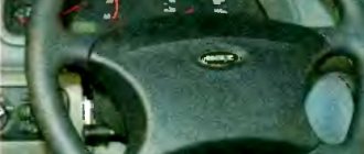
The main rule is that you should not lie on your back, as if in a chaise lounge. Try to keep your back as vertical as possible - this will put less strain on your spine and make steering more comfortable. But vertically should not be taken literally - raise the backrest until you feel the first signs of physical discomfort, and then roll the setting back a little. Now place your hands on the steering wheel with a classic 3 and 9 o'clock grip (use this when driving) - they should be half bent at the elbows.
Keep your back as vertical as possible. If you imagine that the steering wheel is a watch dial, then your left hand should be at the 9 o’clock position, and your right hand should be at the 3 o’clock position. The elbows should be half bent.
If your arms are extended, then this is wrong - you will not be able to rotate the steering wheel at large angles without interception, which means that control of the car is insufficient. Adjust the steering wheel by pulling it towards you (the lock is located on the left of the steering column). If there is no height adjustment, then sometimes it helps to lower the steering wheel a little - there is a height adjustment on any car. Finally, if, with the backrest installed vertically, the steering wheel adjustments are still not enough (this happens), then move the seat cushion a little closer to the pedals.
Extended arms are a common mistake when sitting behind the wheel. In this case, move the chair cushion slightly forward.
There are two techniques to check the steering wheel fit. First, your outstretched wrist should rest on the rim of the steering wheel at 0/12 o'clock. And secondly, you can try a technique from the famous “ring driver”, “king of drift” and journalist Keiichi Tsuchiya: take the steering wheel rim at 2 and 10 o’clock, but not with straight hands, but crosswise. If the position is correct, the arms should not be fully extended at this moment, and the wrists should be approximately at shoulder height.
Checking your driving position - your outstretched wrist should rest on the rim of the steering wheel at 12 o'clock, your elbow should be slightly bent, and your back should be pressed firmly against the back of the seat. Test method from Keiichi Tsuichiya: hold the steering wheel with half-bent arms crosswise at the 2 and 10 o'clock position. Your wrists should be at shoulder height.
[custom_ads_shortcode2]
Steering columns and shafts
In general, the transmission of rotation from the steering wheel to the steering mechanism is carried out by a shaft, which is located inside a special casing called a column. On trucks (Fig. 1), the steering column 3, installed inside the driver’s cab, is attached in the middle part to the inner panel and front panel of the cab. A horn current collector and a turn signal switch can be installed on the steering column. Shaft 8 is installed in column 3 on bearings 7, and steering wheel 4 is connected to the shaft with a key or splines and secured with a nut. The lower end of the shaft has a groove for attaching the cardan transmission fork. In the center of the steering wheel there is a contact device for the horn button.
The steering shaft and steering gear screw are not always pine due to the layout of the vehicle and the need to install the steering wheel correctly. In addition, the thrust between the shaft and the propeller can change, since the cabin, mounted on elastic supports, has the ability to move slightly relative to the frame. Therefore, the shaft is connected to the propeller through a driveshaft 2. On some vehicles with a cab above the engine, a driveshaft between the steering column and the steering mechanism allows the cab to be raised to provide access to the engine and its systems. The cardan transmission of the steering mechanism has two unequal velocity joints, which are similar in design to those used in a car transmission.
If the cabin is located above the engine, the steering column is located almost vertically and to transmit rotation at a large angle to the propeller, an angular gearbox 6 is used in the steering mechanism (Fig. 1, c) with a gear ratio equal to one. Shaft 12 with drive gear 10 is installed in the housing on ball bearings 13, secured with a nut and lock washer. The driven gear 15 is connected to the screw by splines, which allows the screw to move relative to the gear in the longitudinal direction.
***
On passenger cars (Fig. 2a), the steering column includes a shaft 1 located in a pipe that is attached to the front panel. The connection between the steering shaft and the steering gear shaft is most often carried out through an elastic coupling. The shaft rotates on bearing 3, and a steering wheel is mounted on splines at the upper end of the shaft. On modern cars, the steering column can have several adjustment positions vertically and longitudinally to ensure ease of control, which complicates its design.
Steering columns can cause serious injury to the driver in an accident. To reduce the risk of the steering column impacting the driver, a steering wheel is used that can deform upon impact, absorbing part of the impact energy. During an accident, the steering wheel shaft should bend or split without moving more than 127 mm into the passenger compartment. This is done by installing injury-proof steering columns, which are elements of the vehicle’s passive safety.
On a VAZ-2121 car, the shaft folds because it has a cardan drive, and the impact energy in an accident is absorbed by a specially designed steering column mounting bracket.
On the GAZ-3102 car, the energy-absorbing element is a rubber coupling installed between two parts of the steering shaft.
The deformable steering shaft 4 installed on foreign cars can also absorb impact energy in a collision (Fig. 2, b). Such a shaft is a perforated pipe, which can be significantly shortened when a force is applied to it in the axial direction.
The steering shaft can also consist of two parts and are connected by several longitudinal plates, which will bend upon impact, absorbing energy.
***
Academic disciplines
- Engineering graphics
- MDK.01.01. "Car design"
- General structure of the car
- car engine
- Car transmission
- Steering
- Brake system
- Suspension
- Wheels
- Body
- Car electrical equipment
- Basic car theory
- Basics of technical diagnostics
- Fundamentals of hydraulics and heat engineering
- Metrology and standardization
- Agreecultural machines. Agreecultural equipment
- Basics of agronomy
- Transportation of dangerous goods
- Materials Science
- Management
- Technical mechanics
- Tips for graduate student
Olympics and tests
- "Engineering graphics"
- "Technical Mechanics"
- "Engine and its systems"
- "Car chassis"
- "Car electrical equipment"
Worm drive
Here the globoidal worm stands out in the design. It connects to the steering shaft. The design also includes a special roller. This roller is equipped with a bipod, which is not located in the system body. The bipod moves the steering rods.
When the driver rotates the steering wheel, the worm also works, and the roller runs along it. The last thing to change is the position of the bipod and the wheel rods.
This drive is often found in classic models of the Soviet automobile industry. But, this design is sometimes found on both SUVs and trucks. It works just perfectly in trucks. This is how the steering mechanism of UAZ, “Classic” cars and many other models and brands of the domestic automobile industry is designed.
How to set up the steering wheel and pedals
- Adjusting the steering wheel on VAZ models with rear wheel drive
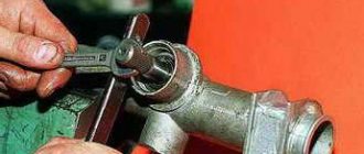
Older Zhiguli models, and the majority of them in our country’s amateur fleet, have not only rear-wheel drive, but also some design features. For example, they do not have a steering wheel height adjustment. An adjustable worm gear reducer somewhat “softens” the situation. It allows you to reduce the amount of play in the steering wheel. This procedure is performed by two people - the driver, who rotates the steering wheel, and the assistant, who tightens the adjusting bolt.
A crookedly installed steering wheel (relative to the position of the steering column splines) is adjusted, as a rule, during the installation of wheel alignment. However, you can do it yourself, although it is unlikely that you will be able to achieve perfect accuracy.
Below is a brief instruction for disassembling the steering wheel, which precedes the process of adjusting the position of the steering wheel on the steering column.
Removing the steering wheel consists of the following steps:
- Disconnect the “-” terminal of the battery.
- We set the car's wheels in a position corresponding to driving in a straight line.
- If the steering wheel has two spokes:
— remove the central trim;
— dismantle the sound signal panel by pressing the fixing latches.
If the steering wheel has three spokes:
— disconnect the clamp by inserting a screwdriver into the recess on the lower spoke.
If the steering wheel has four spokes:
— unscrew the fastening screws located at the base of the hub;
- remove the cover.
- Disconnect the contacts of the audio signal wires.
- Unscrew the screw of the wire fixation bracket (not on all models).
- We indicate the location of the wheel relative to the shaft.
- Unscrew the fixing nut.
- Remove the steering wheel from the steering column shaft splines. This is done using a puller.
The steering wheel is installed in the reverse order after lubricating the horn contact ring and the turn signal switch elements.
2.2 Procedure for adjusting the steering wheel on front-wheel drive VAZs
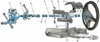
Starting with the tenth model of the Zhiguli, Togliatti developers implemented the ability to adjust the steering wheel in height, bypassing the process of dismantling structural elements. To do this, a special lever (position 9) is installed in the middle part of the steering column, when pulled back it becomes possible to optimize the height of the steering wheel. Returning the lever to its place ensures reliable fixation of the entire steering column.
The possibility of using this function is due to the use of a special “injury-proof” steering control on such models. The steering shaft, structurally consisting of several components, folds in the event of a frontal collision, helping the driver to avoid serious injury.
2.3 Clutch pedal adjustment
This setting allows you to optimize the travel of the clutch pedal with a mechanical drive. It is carried out through the following activities:
- We find in the engine compartment the end of the cable leading from the clutch pedal. Loosen the locknut on the adjusting bolt of this cable.
- By rotating the adjusting nut, we set the amount of travel of the clutch pedal. It should be located in the range of 120-130 millimeters.
- Length adjustment is carried out by rotating the adjusting nut on the tip: tightening - increasing, unscrewing - decreasing.
- Depress the clutch three times and measure the pedal stroke again.
- We repeat the operations until the desired result is achieved.
We adjust the hydraulic clutch pedal as follows:
- We dismantle the spring located on the bracket of the working cylinder and fork.
- By rotating the adjusting nut, we ensure that the distance from the release fork to the pusher rod is 5.0 millimeters.
Summarizing the above, we note that the article provides mini-instructions for performing adjustment work on classic VAZ models of the basic configuration. Therefore, when using them (instructions) in relation to your car, check the technical and operational parameters set by the manufacturer.
How to repair a steering column?
Spline connections cannot be restored, and in this case the entire column must be replaced. To do this, you need to know how to remove the steering column. This is done quite simply. First of all, you need to disconnect the battery. Then the steering wheel of the car and the steering column cover are removed directly. Next, the ignition switch is removed, as well as the switch responsible for controlling this system.
After all the elements have been removed, you need to unscrew the bolts securing the bracket; some of them are almost impossible to dismantle using the standard method, so they need to be drilled out. Next, the bolt connecting the control mechanism and the spline joint is unscrewed. And lastly, the steering column shaft is removed; first remove its lower seal. The new column is installed strictly in the reverse order, so it is better to add all the removed parts sequentially to avoid confusion.
In some cases, it is necessary to replace the steering column bearing. To do this, according to the scheme described above, the bracket assembly with the shaft is removed and installed in a vice, then, having knocked the shaft out of the bracket, we pull out the bearing itself. Then, having inserted the shaft back, you need to knock out the second steering column bearing with a hammer. New bearings are installed with narrow flanges outward and pressed using a mandrel until it stops. The shaft is fixed, and then the second bearing is pressed in. If the steering column crosspiece has become unusable, then the entire part must be replaced.
Adjustment - steering gear
Simultaneously with assembling and adjusting the steering mechanism, the power steering pump is assembled and tested on a special stand.
Below is a description of the procedure for adjusting the steering mechanism of cars.
On MAZ-200 vehicles, the steering mechanism and steering gear are adjusted in the steering control.
| Steering wheel play meter. |
Checking and adjusting the bearings, as well as all other adjustments to the steering mechanism, are made with the front of the car raised or with the mechanism removed.
When checking the clearances in the steering elements and adjusting the steering mechanism, the front wheels of the vehicle must be lifted. When adjusting the steering mechanism, the longitudinal steering rod is disconnected from the bipod, and in some cases the steering wheel is removed from the car.
On KrAZ-214 vehicles and the steering system, adjustments are made to the steering mechanism, steering gear and power steering.
| Steering mechanism of the MAZ-205 car. |
If there is no play in the steering drive connections, adjust the steering mechanism.
In table 198 provides summary data on the magnitude of forces for turning the steering shaft when adjusting the steering mechanism.
Therefore, to ensure ease of control and traffic safety, it is necessary to check the condition of the fastenings daily and periodically adjust the steering mechanism.
| Steering gear. |
An increase in the free play of the steering wheel can be caused by loosening or wear of the ball joints of the steering rods, loosening of the steering gear housing and steering bipod, wear of the roller and worm, worm and roller bearings, and improper adjustment of the steering mechanism. The free play of the steering wheel should be no more than 10 - 15 mm (3 - 5) on a Moskvich-412 car, 12 - 13 mm (5) on a VAZ-2101 car when measured along the rim of the steering wheel. To check, the front wheels are placed in the middle position, corresponding to the vehicle moving in a straight line; turn the steering wheel to the left all the way, but without disturbing the position of the front wheels. Note the position of the steering wheel at any point on the instrument panel and turn the steering wheel to the right, also without disturbing the position of the wheels, and measure the distance traveled with a spoke along the rim of the wheel.
For the power transmission, chassis, brakes and steering: checking the condition of the brake linings and drums, adjusting the gaps between the drums and pads, checking the operation of the pneumatic and hydraulic drive mechanisms to the brakes; washing the air filter-oil separator; checking the operation of the brakes, adjustment of the steering mechanism and its condition; checking the toe-in and camber angles of the front wheels; checking and, if necessary, adjusting the clutch; checking the gearbox, cardan and final drive.
In addition to the listed work included in the constant scope of TO-2, other work can be performed simultaneously as needed: tightening main and connecting rod bearings, grinding valves with grinding of the valve working chamfer and milling valve seats, changing piston rings and liners, cleaning the head from carbon deposits block and exhaust pipeline; disassembling the clutch and riveting the disc linings; disassembling the gearbox and replacing individual gears and bearings in it, cleaning the brake linings on the pads, changing the axle shaft seals, reassembling and lubricating the springs; dismantling the rear axle with washing and checking parts, as well as adjustment work - adjusting the steering mechanism and removing it from the car, flushing the radiator to remove scale; checking and recharging the battery.
How to troubleshoot steering problems
In case of serious problems with the steering system, it is better to contact a service center, because traffic safety depends on the functioning of this system. But a number of malfunctions can be eliminated yourself.
- If the stiffness of the steering wheel is associated with a drop in tire pressure, they need to be inflated immediately.
- If the oil level in the crankcase is below the required level, it should be topped up. If a leak is detected, tighten the bolts securing the cover, replace the gaskets and seals.
- You can try to eliminate the increased play by simply adjusting the amount of free play using special screws that ensure the elements are pressed.
- If the steering wheel sticks or the play increases, the clearances in the hub bearings, hinges, and worm gears (in systems with a worm gearbox) are checked. Gaps are adjusted, fasteners are loosened or tightened, backlash in rivet joints is eliminated or loose rivets are changed, and lubricant is applied as necessary.
- If the hydraulic booster malfunctions, the working fluid is added as necessary, the boot and hoses are replaced, and their fastening is adjusted. It may be necessary to replace worn parts, adjust belt tension, and renew the lubricant.
If adjusting the fasteners and clearances and other measures do not help, you should inspect the parts, dismantle and replace heavily worn or damaged ones. You can use high-quality used spare parts supplied by JapZap from disassembly sites.
- Tie rods are usually not completely replaced. A repair kit is used, which includes tips, pivots, hinges, and bushings. Quite often it is necessary to replace steering tips. Despite the apparent simplicity of this operation, difficulties may arise due to sticking of parts; in this case, a special puller will help.
- It is advisable to entrust steering rack repair to professionals. After replacing failed parts, it is adjusted. In case of extensive damage, it is better to replace the rack completely. If the system uses power steering, after repairing or replacing the steering rack, the working fluid must be replaced.
- The most difficult task is repairing the steering column. It is dismantled, disassembled, and inspected. If individual parts fail, you can use a repair kit, but if there is a large amount of damage, it is more advisable to replace the column. The repaired or new column is installed in place and covered with casings.
Steering column repair requires a highly qualified technician
The serviceability of the steering is extremely important for driving safety. Regular diagnostics and maintenance of this system using high-quality consumables will help avoid serious breakdowns. If a breakdown does occur, immediate repairs are necessary: depending on the nature of the damage, individual components of the system can be repaired or replaced entirely. If the breakdowns are serious enough and your qualifications are not enough to fix them, you should contact a specialist, because driving a car after a makeshift repair is very dangerous.
Amplifier
Elements of power steering for Volga GAZ 31105
An amplifier is used to facilitate control. Thanks to the amplifier, it is possible to achieve greater control accuracy and increase the speed of transmission of movement from the steering wheel to the wheel. A car with an amplifier is easier, easier, faster to drive. The amplifier can be electric, pneumatic or hydraulic. Most modern cars use a hydraulic booster powered by an electric motor.
The hydraulic booster consists of a rotary valve and a vane pump. Due to the movement of the vane pump, hydraulic energy is supplied to the steering mechanism. The pump is powered by the car's electric motor. It moves hydraulic fluid. The pressure is regulated using a safety valve built into the pump. It is not difficult to guess that the higher the engine speed, the greater the amount of liquid entering the pump mechanism.
Rack and pinion control VAZ
The rack is mounted in the engine compartment. The system is housed in a cast aluminum crankcase. The crankcase contains a drive gear. To limit the axial movement of the shaft, a special bearing is used. The inner race of the bearing is held in place by a retaining ring. All nodes are covered with anthers.
The rack is pressed against the gear teeth using a special spring, but not directly, but through a cermet stop. There are marks on the rack for adjustments. The spring is also pressed by an adjustment nut with a locking ring.