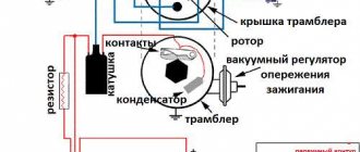
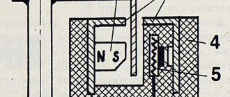
VAZ 2114: dashboard pinout - red and white block (VDO, Schetmash)
Many owners of domestic cars do their own repairs and tuning. If they need to repair or replace electrical equipment, they need to know where a particular wire or connector is connected. For this purpose, there is a pinout of the VAZ 2114 dashboard with a detailed description of their location.
It is worth noting that this car was equipped with VDO and Schetmash devices at different times, which have some differences. Our article presents the pinout of the VAZ 2114 instrument panel for both panel options, indicating the purpose of all blocks, wires and connectors.
The instrument cluster from VDO is more modern. It has stylish LED backlighting, as well as some differences in connecting certain connectors from the previous version. Such devices were installed both at the factory on the latest cars of this model, and are often installed independently by car owners. For example, some drivers install a panel from Lada Kalina.
The pinout of the VAZ 2114 instrument panel in this case looks like this:
- pink and white input – to the electric power steering (if installed independently);
- blue and white - to the emergency warning light;
- gray-blue – leads to the oil pressure sensor;
- brown-blue - to the handbrake switch;
- blue with yellow - leads to the immobilizer control unit (not used on 2114);
- black – to the block that controls the airbag (not applicable on the “fourteenth”);
- yellow – to the lighting switch (external);
- blue – leads to the right direction indicator;
- black and blue - to the left turn signal;
- white-blue – to the electronic control unit;
- to a sensor showing the degree of wear of the brake pads (this VAZ is not installed on this model);
- to the seat belt sensor;
- black - leads to the block that controls the traction control system (not installed on the 4);
- red-blue – “RESET” key on the steering column switch;
- blue with pink - to the brake fluid level sensor;
- black – to ABS (VAZ 2114 does not have it);
- green – leads to the high beam switch;
- white – goes to the instrument panel lighting control;
- brown – tidy weight;
- white-red – terminal 30;
- orange – terminal 15;
- red-yellow - to the sensor indicating fuel consumption;
- orange-white – MK “Forward” key;
- white-black – MK “Back” key;
- black and white – outside temperature sensor (-);
- yellow-green – outside temperature sensor (+);
- pink - to the fuel level sensor;
- gray – leads to the speed sensor;
- green-white – to the coolant level sensor;
- brown-red – to the tachometer (low voltage);
- service (for panel diagnostics);
- terminal L of the relay-regulator on the generator.
Since such a tidy is also used on the Lada Kalina, equipped with more modern equipment, some inputs when installed on 2114 will remain free, since this car does not have such equipment (unless, of course, it was additionally installed by the owner himself).
VAZ 2114 instrument panel pinout
Electrical connection diagram for the VAZ 2114 instrument panel (Click on the picture to enlarge)
The panel pinout is a diagram, but the diagram described in words seems easier for many. The contacts located on the instrument panel, and there are only 26 of them, are responsible for the operation of the indicators on the panel itself.
If a plus is applied, then each of the contacts shows information and the state in which the car is currently located. The panel is equipped with sensors and signal indicators, and the panel is controlled using an electronic unit.
Inside the panel there are two pads - red and white. Fuses, inputs and outputs, controllers are connected to a specific plug. If the sensors fail, they need to be replaced.
You can check the serviceability of the wiring by disassembling the instrument panel. Oxidized or damaged wires must be replaced. Indicator lights may fail. Burnt out light bulbs must be replaced with new ones.
A faulty lamp sensor must also be replaced. The contact between the board and the lamp must be well connected, otherwise the ends of the contacts should be cleaned, bent, and if necessary, replace the lamp socket.
If the backlight stops working or the radio is faulty, the fuse must be replaced. Maybe the damage is not in the fuse, but in the wiring, which also requires replacement.
A short circuit in the fuse can also damage it.
Schetmash
The “Schetmash” instrument panel was set to “fourteenth” from the first days of production. Subsequently, VDO devices began to be installed on the car. But even among the cars of recent years, there are sometimes cars with this panel.
For this device, the pinout of the VAZ 2114 instrument panel is as follows:
For white block (X1):
- 1 black – weight per body;
- 2 purple - brown - to the tachometer (input from the ECU, low voltage);
- 3 yellow – tachometer (input from the ignition module, high-voltage);
- 4 purple - white - fuse F3;
- 5 white-green – antifreeze level sensor;
- 6 brown – fuse F10;
- 7 reserve;
- 8 purple - white - Check Engine;
- 9 pink - black - to the electronic control unit;
- 10 orange – sensor indicating the gasoline level;
- 11 brown-blue - to the hand brake;
- 12 white-brown - to output D on the generator;
- 13 blue-blue – engine oil level sensor.
For the red chip (X2):
- 1 purple-blue - to the outside air temperature sensor;
- 2 orange - fuse F16;
- 3 black - weight per body;
- 4 white — dashboard lighting;
- 5 blue - to the right direction indicator;
- 6 black and blue - to the left turn indicator;
- 7 pink-blue - brake fluid level sensor;
- 8 brown - leads to the on-board computer;
- 9 yellow-gray - sensor indicating speed;
- 10 pink - fuel level sensor;
- 11 black-green - fuse F14;
- 12 – to the alarm;
- 13 purple - terminal 50 on the ignition switch.
Car diagnostics
The appearance of a lit “Check Engine” lamp on the instrument cluster signals the driver that a problem has arisen in the vehicle’s electrical system. You need to understand that checking the vehicle yourself and at a service station can give different results. Special equipment available to professionals will allow more accurate detection of faults.
Self-diagnosis
On a VAZ 2115, the owner can do independent diagnostics and find out what errors are stored in the memory of the engine control unit. The procedure is carried out by calling up fault codes on the dashboard or using a diagnostic adapter.
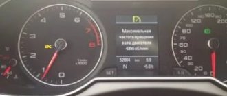
To carry out diagnostics on the electronic instrument panel, you must perform a certain sequence of actions:
- Sit in the driver's seat of the car, insert the key into the ignition and press the daily mileage reset button located on the instrument cluster.
- Turn the lock key to the ignition switch position.
- Release the key, starting the self-diagnosis process. Visually, this will look like turning on the backlight, all signal lamps, possible symbols on the LCD screens and testing the instruments (the arrows will move across the entire scale in both directions).
- Press the key again and release. The second press displays the software version of the instrument cluster on the screen located under the speedometer (inscription like Uer x. x).
- Press the key again, after which the errors in the memory will be displayed on the screen.
Instrument cluster VAZ 2115, the button is located on the right side of the speedometer
We recommend: Crankshaft sensor VAZ 2112 16 valves photo
The driver can perform self-diagnosis on the electromechanical panel and the “January-4” control unit according to the following sequence:
- Turn off the ignition.
- Open the diagnostic connector cover located on the center console.
- Connect contact B to the negative terminal of the battery (to the body). Contact A, connected to the engine crankcase, is suitable for this.
- Turn on the ignition. The “Check Engine” lamp will flash code 12, which means the diagnosis has begun. The light signals are given as follows - a long flash, then a pause (about 2 seconds), two short flashes, a long pause (about 3 seconds). Signal 12 is sent three times. If there is no signal, the diagnostic system is inactive or faulty. After this, the Check Engine light will flash and list the errors in memory. Each code is repeated three times. If there are no errors in the memory, code 12 will continue to be transmitted.
Electromechanical instrument cluster Pinout of diagnostic connector
To read controller errors, a special K-Line adapter is used, which is connected to the diagnostic connector using a connector. This connector is located on the center console behind a plastic plug (below the cigarette lighter and ashtray). The adapter has a cord with a USB connector at the end that connects to any laptop. A special program for reading and resetting errors must be installed on the device (OpenDiagFree version 1.4 or 1.6).
The procedure for reading errors is quite simple, you need to:
- Check the level of process fluids.
- Open the connector cover and turn on the ignition.
- Connect the adapter or scanner to the diagnostic socket.
- Launch the software on the laptop.
- View available errors in the program dialog box.
- Decrypt the codes using the program interface or decryption table.
- Eliminate the causes of malfunctions and re-diagnostics.
Wiring diagram for VAZ 2114 and VAZ 2115. Pinouts
The modern VAZ 2114 model is in demand among domestic drivers due to its sufficient reliability, optimal cost and high maintainability. The only drawback of the model is the poor build quality. Some cars suffer from frequent electrical failures. Consequently, users often try to deal with breakdowns on their own, which without the necessary knowledge can aggravate the situation.
Complete electrical diagram of the VAZ 2114 with decoding
The complete package of electrical equipment of the VAZ 2114 can be divided into two types. The fundamental differences are due to changes in equipment depending on the year of manufacture and equipment of the car. In this case, the entire drawing can be divided into several zones.
- The engine compartment is responsible for providing voltage to sensors and instruments located directly inside the engine compartment.
- Salon compartment. The part is primarily used to connect the front and rear compartments.
- Instrument panel assembly. The pinout is displayed directly on the controls and dashboard. All elements of the on-board network are combined here and connected to buttons or indicators.
- Stern joint. The small module combines chain elements located at the rear of the machine. Typically, the segment is subject to frequent damage, which is due to the constant transportation of goods in the luggage compartment. When moving over obstacles, loads can damage sensitive equipment.
You can also separate small units – these are door units, windshield wipers and others. For ease of perception, each beam is considered separately.
VAZ 2114 instrument panel pinout
The terminals of all vehicle equipment are concentrated here. Due to the fact that the unit is located under the dashboard and is subject to constant condensation or fogging, some users treat it with hot melt adhesive. Even a thin coating can reliably protect the device from water ingress.
Elements are connected to devices or controls:
- 1 – switch key for heated rear glass;
- 2/6 – fog light switches, for rear/front module;
- 3 – plastic block for activating head optics and turn signals;
- 4 – fuse block;
- 5 – wiper mode switch;
- 7 – on-board system indication;
- 8 – supply voltage to the additional harness;
- 9 – dashboard;
- 10 – “male” for powering the on-board computer;
- 11 – terminal to the ignition device;
- 12 – for door wiring;
- 13/14 – fuses;
- 16 – ignition break;
- 17 – stove motor;
- 18 – secondary resistance of the stove;
- 19 – current supply to the ignition unloading relay;
- 20 – protective relay for rear fog lights;
- 21 – starter fuse relay;
- 22 – remote socket for a portable lamp;
- 23 – power supply for the cigarette lighter;
- 24 – for illumination of the glove compartment;
- 25-27 – illuminators;
- 28 – stove switch;
- 29 – tidy lighting with rheostat;
- 30 – stop switch;
- 31/32 – horn/hazard warning switch, respectively;
- 33 – backlight of the stove panel;
- 34 – fuse;
- 35 – protective relay for seat heating elements;
- Ш1/4 – mounting block jumpers;
- X1/2 – dashboard controls;
- A – protective ground output (usually black).
Which wire goes where?
First, let's look at the back of the instrument panel. At the top there are:
- fuel level indicator;
- dashboard lighting lamps;
- control of right and left turns (separately);
- tachometer;
- block with many plugs;
- coolant temperature gauge.
As you can see, there is really nothing particularly complicated here. At the bottom of the instrument panel on the back side there are controllers:
- high beam;
- "emergency lights";
- CHECK ENGINE;
- battery charge;
- parking brake;
- oil pressure;
- air damper (for models with a carburetor);
- outdoor lighting work.
In addition, there is also a speedometer and a brake fluid level indicator lamp.
Now let's take a closer look at the pads. There are two of them - white and red. In the first, the connectors and wires look like this (in order):
- Ground wire black.
- Red-brown – low-voltage supply from the ECU to the tachometer.
- Yellow – high-voltage supply to the tachometer from the coil.
- Red-blue - comes from the battery through the 6th fuse Const with a voltage of 12 volts.
- Green-white - leads to the coolant temperature sensor.
- Green-yellow – fuse F1, responsible for the side lights.
- This connector has no color, it goes to the throttle valve.
- Red and white – leading to the CHECK ENGINE indicator light.
- 2 orange wires leading to two F19 + 12 volt power fuses.
- Same as the previous connector.
- 2 blue-brown wires leading to the “VK” terminal of the handbrake.
- The output to terminal D of the generator is a brown-white wire.
- Gray and blue - wire going to the oil pressure sensor.
In the red block, the connector number according to the account, the color of the wires and the devices to which they lead are as follows:
- Red-blue – leads to the external temperature sensor.
- Orange – goes to power fuse F19 + 12 volts.
- 2 black ground wires.
- White – leads to the instrument lighting switch.
- Blue – to the right turn indicator.
- Blue-black - to the left turn indicator.
- Blue-pink - to the brake fluid level sensor.
- Brown – leads to the on-board computer.
- Gray - to the speedometer.
- Pink – to the fuel level indicator.
- 2 green-black wires leading to fuse F3, which is responsible for the high beam.
- Blue-white - to the hazard warning switch.
- The white wire leads to terminal 50 - the ignition switch.
It is worth especially noting here that the most typical and common pinout diagram is shown above. However, different manufacturers may have differences in color markings. For example, in the instrument panel manufactured by the Kursk "Schetmash" there will be minor differences from the above diagram, in particular in the red block (connector number and wire color):
- black;
- red-brown;
- yellow;
- red and white;
- green-white;
- 2 brown wires;
- empty;
- red and white;
- blue;
- orange;
- blue-brown;
- white-brown;
- blue-gray.
As you can see, there are still certain differences, even if they are small. However, these little things are very important. Therefore, it is best, before starting work, to find out which panel your car has (by year of manufacture and manufacturer), and then find the correct pinout diagram. However, there is another option - the self-adhesive pieces of paper already mentioned above. When disconnecting the wires, be sure to label them - this will greatly facilitate the assembly process.
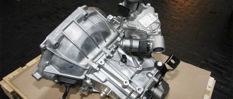
Instrument cluster VAZ 2110-11-12: All control devices of the car are combined into an instrument cluster. It includes: electronic speedometer and tachometer, coolant temperature indicator, fuel level indicator and 12 warning lamps. The instrument cluster is secured in the instrument panel socket with two screws. Instrument panel combinations are produced by the manufacturers Schetmash Kursk and VDO. In addition, on a VAZ 2110 you can install an instrument panel from a VAZ 2115 (with two windows), the instrument panel combination will display the correct information. In addition, there are combinations of instrument panels with a mechanical odometer.
Connection diagram of the instrument cluster VAZ 2110 2111 2112 (view from the back of the instrument cluster)
| Fig. 1 pinout of the VAZ 2110 instrument panel combination | |
| 1 – fuel reserve warning lamp; 2 – instrument cluster lighting lamps; 3 – right turn indicator lamp; 4 – left turn indicator lamp; 5 – plug block; 6 – coolant temperature indicator; 7 – indicator lamp for external lighting; 8 – control lamp for the carburetor air damper; 9 – oil pressure warning lamp; 10 – parking brake warning lamp; | 11 – battery charge indicator lamp; 12 – tachometer; 13 – control lamp “CHECK ENGINE”; 14 – speedometer; 15 – brake fluid level warning lamp; 16 – hazard warning lamp; 17 – control lamp for high beam headlights; 18 – fuel level indicator. Plugs 2, 3 , 8 , 9 in block X2 are speedometer pins 14 |
Instrument cluster.
All vehicle control devices are combined into an instrument cluster. It includes: electronic speedometer and tachometer, coolant temperature indicator, fuel level indicator and 12 warning lamps. The instrument cluster is secured in the instrument panel socket with two screws.
The connections of the instrument cluster are made by printed wiring on a board made of foil getinax. The board is attached to the back of the case. The connection diagram of the instrument cluster is shown in Fig. , the addresses of the plugs are in the table “Addresses of the output plugs of the instrument cluster”
The speedometer has two trip counters: one total, and the second “daily”. The daily counter can be set to zero using a button located on the instrument cluster itself. The daily meter can only be reset while the vehicle is stationary.
Some manufactured vehicles may have an electronic instrument cluster installed. It contains the same instruments and warning lights as the conventional instrument cluster. The instrument cluster can only be checked on a stand in a specialized workshop. The instrument cluster is beyond repair.
On-board control system display unit.
The unit contains an electronic control circuit with an audible alarm and 10 LED indicators: insufficient oil level, insufficient coolant level, insufficient washer fluid level, faulty exterior lighting lamps, unfastened seat belts, worn front brake pads and four open door indicators.
The addresses of the block plugs are given in the table “Addresses of the output plugs of the on-board monitoring system display unit.”
The order of the conditional numbering of the block plugs is similar to the numbering order of the plugs in the instrument cluster blocks (see Fig.
Connection diagram of the instrument cluster (view from the back side)
).
Addresses of the output plugs of the instrument cluster
| Plug | Pad address | |
| white (X1) | red (X2) | |
| Housing ("mass") | To terminal “W” of the fuel level indicator sensor | |
| Low voltage tachometer input | ||
| High voltage tachometer input | Housing ("mass") | |
| Spare | To the instrument lighting switch | |
| To coolant temperature sensor | To turn signal switch (starboard side) | |
| To fuse F1 of the mounting block | To turn signal switch (left side) | |
| To brake fluid level sensor | ||
| To the motor control controller | To the on-board computer | |
| To fuse F19 (“+” power supply) | To speed sensor | |
| To fuse F19 (“+” power supply) | To terminal “T” of the fuel level indicator sensor | |
| To the parking brake switch | To fuse F3 of the mounting block | |
| To terminal "D" of the generator | To hazard warning switch | |
| To oil pressure warning light sensor | To terminal “50” of the ignition switch | |
Addresses of the output plugs of the on-board control system display unit
| Plug | Address (purpose) of plugs |
| To fuse F19 (“+” power supply) | |
| Housing ("mass") | |
| To the lamp health monitoring relay | |
| To ignition switch microswitch | |
| To the lampshade | |
| To rear left door sensor | |
| To rear right door sensor | |
| To oil level sensor | |
| To coolant level sensor | |
| To washer fluid level sensor | |
| To the seat belt sensor | |
| To brake pad wear sensor | |
| To front left door sensor | |
| To front right door sensor |
* On right-hand drive vehicles, plug 2 is connected to ground.
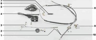
Electrical equipment of the front of the car
The following is a breakdown of the front cable bundle, excluding fog lights:
- 1 – output terminals of the starter contact group;
- 2 – battery, connection of power cables;
- 3 – standard “father” of the generator;
- 4 – blocks for connecting the power conductors of the battery and generator to the front assembly of electrical equipment;
- 5 – part of the fuse mounting block;
- 6 – standard horn;
- 7 – sensor that measures the temperature of antifreeze in the power plant;
- 8 – standard sensor for measuring the washer fluid residue in the tank; when activated, the corresponding indicator on the device lights up;
- 9/10 – left and right headlights, respectively;
- 11 – external thermometer;
- 12 – standard reverse gear lamp switch;
- 13 – drive of the electric fan of the generator;
- 14 – connector to the ignition system module;
- 15 – in the VAZ 2114 scheme the injector is not used, it is used only for the carburetor;
- 16 – electronic brake fluid level sensor; in case of a critical drop, an exclamation mark lights up on the instrument panel;
- 17 – built-in oil level sensor in the crankcase compartment of the power plant; when activated, the red light on the instrument panel lights up;
- 18 – similar for the engine cooling system;
- Ш5-8 – mounting block connectors;
- A1/2, B1/2 – grounding terminals.
How to decipher codes
If you do not know what the data displayed on the display means, then it is pointless to independently check the functionality of the sensors. Therefore, it is important to know how to decipher combinations. The following numbers appear most frequently:
- If code 1 appears, then the fault lies in the microprocessor of the on-board unit itself. This error can be corrected by changing the computer software. It is important to use only official firmware, otherwise you will damage the entire electrical system of the car.
- If the malfunction is hidden in the incorrect operation of the fuel sensor, then 2 will appear on the display. The same number means problems with the electrical wiring, especially if it is displayed in addition to 8.
- When the voltage in the network is high, error 4 appears, and when voltage is low, error 8 appears. If you notice these data, then you need to check the generator and battery. VAZ-2115 owners most often encounter generator malfunctions. It will need to be repaired or completely replaced.
- Malfunctions in the operation of the control lamp in the diagnostic circuit are displayed on the display in the form of a combination - 12.
- Failure of the oxygen level sensor is displayed as error 13. Check the filters, most often they are the cause of this combination. Combinations 33 and 34 indicate mass air flow. In this case, you may need to replace the sensor itself. A malfunction of the controller itself is indicated by code 61 displayed on the display. Experts recommend that if one of these combinations occurs, a full check of the functionality of the vehicle components is carried out. Start with the electrical wiring.
- Car enthusiasts often encounter combinations 14 and 15, which may appear along with an indicator indicating the need to add antifreeze. It is important to interpret this malfunction correctly - the appearance of this data on the display means that the temperature in the system is increased or decreased. The reason for this may be a malfunction of the thermostat. If the node is not damaged, then the problem most likely lies in the control unit.
- Combinations 16 and 17 are output when the voltage in the on-board network is insufficient or too high. It is necessary to check all wiring for short circuits and breaks.
- Code 19 occurs if the crankshaft position sensor does not respond correctly to the test. In this case, it is necessary to check the vehicle with an external device. If it shows a combination in the range from P0340 to P0343, then the breakdown may be hidden in the controller itself.
- With error 24, the on-board computer stopped receiving data about the vehicle speed.
We recommend: Characteristics of the generator for the VAZ 2101, diagram of its connection, disassembly and assembly
The combinations listed above occur extremely often. If the display shows a different number, refer to the vehicle's technical documentation. In most cases, to identify a breakdown, it is necessary to check the electrical circuit. Since most often problems arise precisely there, and errors are the result of incorrect processing of requests by sensors.
As stated above, without deciphering error codes, diagnosing a vehicle is meaningless. Therefore, deciphering combinations should also be given attention. Especially if you don’t want to pay a lot of money to specialists at the service station for this. So, let's start with the combinations that appear during self-diagnosis of the car.
Self-diagnosis codes
| Combination | Deciphering the breakdown |
| 1 | Code 1 indicates a malfunction in the microprocessor. Sometimes the error is corrected by flashing the device. |
| 2 | The on-board computer reports incorrect operation of the gasoline level sensor in the fuel tank. There may be problems with the electrical wiring. |
| 4,8 | The voltage in the vehicle network is too high or too low. |
| 12 | Incorrect operation of the diagnostic lamp circuit. |
| 13 | The on-board computer stopped receiving a signal from the oxygen level monitoring device. |
| 14,15 | The control unit receives an incorrect signal from the antifreeze temperature sensor in the cooling system. In particular, the signal may be too low or too high. |
| 16,17 | When checking a car for errors, these combinations mean an incorrect on-board voltage indicator. it is necessary to carefully check the network for short circuits and breaks, since the voltage indicator is too high or very low. |
| 19 | The VAZ 2115 on-board computer receives an incorrect signal from the crankshaft position monitoring device. The circuit should be checked. |
| 21,22 | The VAZ 2115 control unit receives a very low or high signal from the throttle position control device. To eliminate the malfunction, you should check the functionality of the device itself, as well as diagnose the electrical wiring. |
| 23,25 | Intake air temperature control device. The control unit receives an incorrect signal from this sensor. The circuit should be checked, as well as the sensor itself. |
| 24 | The on-board computer stopped receiving a signal from the speed sensor of the VAZ 2115 vehicle. |
| 27,28 | These error combinations indicate the receipt of an incorrect signal from the CO sensor to the car control unit. It is recommended to check the circuit for opens and shorts or replace the sensor. |
| 33,34 | Mass air flow control device. These errors mean the receipt of an incorrect signal from the sensor, as a result of which it should be replaced. There is also a possibility of breaks in the circuit, so it makes sense to check the electrical wiring as well. |
| 35 | A malfunction has been detected in the operation of the idle air regulator. The sensor must be replaced to restore correct operation of the device. |
| 41 | The control unit receives an incorrect signal from the phase sensor. |
| 42 | This combination indicates a malfunction in the electronic ignition control wiring. Apparently, everything is in order with the ignition, but the circuit should be diagnosed. |
| 43 | The control unit received an incorrect signal from the knock sensor. You should check the device or diagnose the circuit for breaks. |
| 44,45 | In the injection system, the on-board computer recorded a lean or enriched composition of the combustible mixture. In this case:
|
| 51,52 | These combinations of faults indicate detected errors in the PROM or RAM devices. |
| 53 | The VAZ 2115 control unit stopped receiving a signal from the CO sensor. You should check the functionality of the device. |
| 54 | The signal from the octane corrector sensor has disappeared. |
| 55 | This combination indicates that when the car is moving, in particular when there is a high load on the VAZ 2115 engine, the combustible mixture in the injection system becomes leaner. In this case, the signs of failure may be the same as in the case of codes 44 and 45. |
| 61 | The oxygen sensor is broken. To restore system operation, the sensor must be replaced. |
Connecting special diagnostic equipment to the connector in the VAZ 2115 interior
We recommend: How to check the Matiz ignition coil
We recommend: Errors 84 and 89 on Chevrolet Cruze: what they mean and how to get rid of them
Controller errors
The following are combinations of errors in the operation of controllers that arise when diagnosing a VAZ 2115.
| Combination | Decoding |
| P0101-P0103 | These combinations indicate a malfunction of the mass air flow sensor. In particular, the signal may be increased or decreased. The device should be replaced. |
| P0112-P0113 | The intake air temperature sensor has been reported to have failed. It is necessary to check the electrical wiring, especially in places where the wires have been soldered. Apparently, the on-board computer is trying to inform you that a short circuit or break has occurred. |
| P0116-P0118 | These error codes indicate a malfunction of the antifreeze temperature sensor in the system. As a rule, in such cases, it is better to first check the electrical wiring, and if everything is in order with the circuit, then it is advisable to replace the sensor itself. |
| P2138, P2122, P2123, P0222, P0223 | These error codes indicate that the accelerator pedal position control device is not operating correctly. |
| P0201-P0204 | When such combinations appear, the on-board computer tries to inform the car owner that one of the injectors is not working correctly. In particular, an open circuit or short circuit may be detected in the system. |
| P0130 - P0134 | One of these combinations of numbers may indicate a malfunction in the functioning of the control oxygen sensor. To restore the operation of the sensor, you should check the circuit for breaks and short circuits, or you should replace the device. |
| P0136-P0140 | These errors indicate incorrect operation of the diagnostic sensor for monitoring the oxygen level in the injection system. As in the previous case, errors may indicate incorrect operation of the device or faulty wiring. |
| P0217 | Indicates overheating of the internal combustion engine. In this case, malfunctions may lie both in the operation of the motor itself and in:
|
| P0326-P0328 | The VAZ 2115 on-board computer informs the car owner about a detected breakdown of the knock sensor. In particular, such combinations may indicate not only the failure of the sensor, but also an incorrect signal coming from it to the control unit. |
| P0340-P0343 | Such combinations indicate a breakdown of the VAZ 2115 camshaft position control sensor. In particular, errors may mean:
|
| P0351, P0352, P2301, P2304 | These combinations mean incorrect operation of the ignition coils, namely, we are talking about an incorrect signal sent to the on-board computer. Also, these combinations may indicate a break in the electrical wiring or a short circuit in the circuit. |
| P0422 | The neutralizer device has broken down. |
| P0691, P0692 | The first cooling fan relay has failed. |
| P0693, P0694 | The on-board computer detected a breakdown of the second cooling fan relay. If the fuse is not replaced in a timely manner, the coolant may boil. |
| P0485 | The control unit receives an incorrect voltage signal from the cooling fan. |
| P0560-P0563 | The control unit has detected that the on-board voltage is too low or too high. |
| P0627-P0629 | These combinations may indicate either an incorrect signal from the fuel pump or a breakdown of the relay responsible for the operation of the unit. It is worth noting that if the fuel pump fuse breaks, operation of the vehicle will be impossible, since it will not be possible to start the engine. |
| P1602 | 1602 is a common VAZ error. Malfunctions have been registered in the operation of the engine control system controller. |
Reset error
Disconnecting the battery terminal to clear codes
If you have discovered and eliminated a malfunction, then it must be erased from the memory of the on-board computer. To do this, repeat the following steps:
- Stop the engine and turn off the ignition.
- Disconnect the terminals from the battery.
- Wait a few seconds and connect the terminals back to the battery.
Wiring diagram VAZ 2114 injector: decoding of rear harness contacts
Here are the conclusions of the equipment located in the rear of the vehicle:
- 1 – output of the mounting unit;
- 2 – windshield heater;
- 3 – electric drive of the rear wiper gearbox;
- 4 – diodes for illuminating the stern license plate;
- 5 – license plate illuminator directly, some users connect diode strips here for better lighting;
- 6/7 – illuminated direction indicators, for the left and right sides, respectively;
- 8 – lamp for individual illumination of useful space;
- 9 – interior lighting lamp, usually located in the ceiling, above the steering seats;
- 10 – handbrake lever position indicator;
- 11/12 – left and right side lighting lamp;
- 13 – power supply to the additional brake light indicator;
- 14-17 – group of interior lighting switches located in the door pillars;
- Ш9 – terminal block of the fuse mounting device;
- A1 – license plate grounding;
- A2/7 – standard grounding points.
Schematic diagram of the VAZ 2114 stove: a separate line responsible for powering the windshield wiper
A small cable harness responsible for powering and controlling the cabin air supply box. There is also a power supply for the windshield wiper:
- 1 – part of the installation site exit;
- 2 – sensor for monitoring lubricant pressure in the crankcase compartment of the power plant;
- 3 – power lines of the aft windshield washer motor;
- 4 – voltage to windshield washer drives;
- 5 – diagram of the electric motor for windshield wipers;
- Ш11 – terminal for connection to the installation site;
- A – grounding terminals of the wiring section.
Electrical connection diagram for VAZ 2114, additional segment
Here are grouped auxiliary equipment that is not related to the power plant or on-board computer of the car:
- 1 – contact group of wiring from the doors to the instrument panel block;
- 2 – a similar terminal intended for connecting heated seat devices for the driver and front passenger;
- 3/4 – central locking drive, sections of the front left and right doors, respectively;
- 5/6 – contact blocks of the front right and left speakers, respectively;
- 7 – electronic central locking control unit;
- 8/9 – connecting door parts of electrical equipment to the auxiliary left beam;
- 10 – terminal for connecting the standard speaker system;
- 11 – “mother” of doors to the right wiring harness for connecting electrical equipment;
- A1 – connection of grounding electrical wiring.
General diagram of devices
If you look from the back of the instrument panel, here it is in sequence - from top to left to right:
- Fuel level indicator;
- Combination of instrument lighting lamps;
- Right turn control;
- Left turn control;
- Tachometer;
- Next is the block, there are a lot of plugs in it;
- And the top part of the dashboard is completed by an antifreeze temperature indicator.
VAZ 2110 dashboard connection diagram
The lower part of the dashboard (also from left to right and from the back of the dashboard). The following part of the instruments is located here:
- high beam controller (bulb);
- alarm controller;
- brake fluid level control lamp;
- speedometer;
- CHECK ENGINE controller;
- battery charge control;
- parking brake controller;
- oil pressure controller;
- air damper controller in the carburetor;
- outdoor lighting controller.
VAZ 2114 wiring diagram: section of the right front door
The cut is a simplified concept due to the minimal amount of equipment. The most budget version is completely absent.
- 1 – “mother” of the rear harness, suitable for the door wiring;
- 2 – power supply to the electric motor for the front passenger window;
- 3 – terminal block to the standard door speaker;
- 4 – door lock servo motor (part of the central lock);
- 5 – power switch and power window drive mode switch;
- A – grounding bus.
Wiring diagram VAZ 2114: driver's door
A larger section of standard on-board wiring:
- 1 – contact group for connecting to the wiring of the additional bundle;
- 2 – similar output to the aft left beam;
- 3 – electric window motor drive;
- 4 – standard output of the block to the front speaker of the standard acoustic system;
- 5 – door lock drive;
- 6/7 – power window control buttons, for left and right, respectively;
- A1 – standard protective grounding terminal.
Wiring diagram VAZ 2114 injector - a separate section of seat heating equipment
A specially dedicated section of on-board wiring responsible for powering, activating and adjusting seat heater devices. Here is a detailed description of all structural elements:
- 1 – driver’s seat heater;
- 2 – output to the terminal block of the dashboard;
- 3 – separate connector for the driver’s door, wire supply to the control button;
- 4 – heating element of the front passenger seat;
- 5/6 – adjustment key for the element specified in paragraphs No. 1 and 4;
- A1 – grounding wire, fastened with a bolt to the car body.
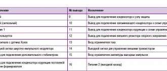
Pinout of on-board computer VAZ 2114
In standard drawings of electrical equipment, the BC block section is missing due to its uselessness. Initially, it is assumed that the motorist will not independently repair or maintain the complex control unit. But some users still take risks and install the system themselves. In older versions of cars, such a module is missing or insufficient for comfortable operation of the car in its modern form.
To connect wires to the module, you will need to buy a standard 9-pin header and connect the following wires to it:
- 1 – green wire comes from the fuel consumption sensor;
- 2 – the ignition cylinder is powered through an orange cable;
- 3 – power core from the battery, usually a red wire with a white stripe is supplied;
- 4 – grounding or ground, standard color – black;
- 5 – 6k line, usually a gray wire;
- 6 – Mute – green shell with a red line;
- 7 – the backlight in the standard pinout is output from the marker optics key;
- 8 – a sensor that displays the remaining fuel in the car’s gas tank can be connected directly.
How to prevent electrical equipment breakdowns?
In order for the VAZ 2114 pinout to be required as rarely as possible, the user is required to follow a number of simple rules and recommendations.
- Periodically treat all metal parts with special oil. In this case, it is first necessary to clean the copper patches from oxides and traces of corrosion. Such lesions provoke a deterioration in the transmission of signals, which can be perceived by the car as a breakdown.
- Every 20-30 thousand kilometers, check all equipment and plastic plugs for looseness or reduced fastening rigidity. With constant vibrations typical of vehicles, plastic clamps can fail and cause breakdown.
- Monitor the correct battery charge and the serviceability of the generator. Some machine devices do not work correctly when there is a strong voltage drop.
- Every 40,000 km, check the condition of the wires themselves. With constant use, the braids of the power cores may crack or dry out, which increases the likelihood of a short circuit in the on-board lines. This may also cause a fire.
The most complete wiring diagram for the VAZ 2114 is in the factory instructions for repair and maintenance of the car. Such documentation is supplied to official dealer centers and specialized workshops.
Source
How to disassemble the dashboard of a VAZ 2114
Before embarking on this complex process, the driver must carefully familiarize himself with the design and arrangement of the instrument panel on his car. When disassembled down to the cogs, it looks like this:
If you carefully study this diagram, it becomes clear how to remove the panel on a VAZ 2114. Having determined the order for yourself, you can begin the process.
- Using a Phillips screwdriver, you need to unscrew the three screws holding the left console screen. For convenience, when doing this work, it is better to use a screwdriver with a short handle and blade.
- When removing the screen, carefully remove the lower edge of the trim from the body bracket.
- The right console screen is secured with five self-tapping screws. Using a Phillips screwdriver, carefully unscrew all the screws while holding the trim with your hand.
- Remove the screen without allowing it to get caught in the wiring harnesses that are hidden behind it.
- Disconnect the ground from the battery by disconnecting the connectors. If your car has a radio, disconnect it from the main bundle of wires by pulling out the connecting connector. If there is no radio installed on the car, then simply pull the wires out of the panel; they should be closed with a plug. Be sure to turn off the cigarette lighter and remove the socket with the ashtray light bulb.
- Remove the handles from the heater damper control levers. To make the process easier, pry them off with a flat-head screwdriver.
- Despite the apparent simplicity of this item, removing the handles from the levers can take a lot of time. To do this, a clear example is given of how this should be done on a removed unit.
- Remove the electric heater fan handle by simply pulling it towards you.
- Unscrew the cross-head screws securing the instrument panel to the brackets on the right and left with a screwdriver
- In the window on the instrument panel, where the instrument unit is located, there are two self-tapping screws at the top and two at the bottom - under the window. It is necessary to turn them out, loosening the cover (2) and the shield (8).
- Pull out the plug and unscrew the screw located behind it
- Remove the two screws from the bottom that hold the trim and remove it.
- Having marked the wires suitable for the switches, disconnect them.
- Remove the bolts from the steering wheel bracket
- Using the “8” key, unscrew the screws of the lower bracket fastening.
- Unscrew the self-tapping screw and remove the light guide.
- Remove the fasteners from the heating control unit and remove the cartridges from the back of the unit.
- remove the decorative insert, removing all external parts.
- Unscrew the nuts with a key set to “21”.
- Remove the hydraulic corrector illumination.
- Unscrew the upper and lower fastenings of the panel, and remove the fastening to the cross member on the left side.
- Now you can remove the VAZ 2114 torpedo.
- Installation is in the reverse order.
In order to clearly see the whole process in motion, you can watch a video on how to remove the dashboard on a VAZ 2114.