regulation
If your paw feels tight, you can try adjusting it.
There are two ways to adjust your feet on a work machine, the first is like a "book", the second is often used in auto repair.
- We parked the car in a pit.
- Remove the clutch housing pan.
- Remove the clutch cover so it can reach the paws.
- We take a rod (slightly longer than a match) and use it as a measuring tool. Rotate the flywheel, select the least hanging leg and use a rod to measure its height from the flywheel. The other two legs should be set at the same height. Turn the nuts in the desired direction for adjustment, the nuts are on the outside near the tabs.
- Having installed all the levers (paws) at the same distance, we check the operation of the clutch while driving. If everything is set up correctly, be sure to secure the adjustment nuts to the basket.
- Install the clutch housing. Job is done.
The first method is not always able to adjust the clutch. The fact is that the legs go into needle bearings, and wear may occur as a result. Then the second adjustment method will be somewhat more effective. All operations are performed the same way, only the essence of the adjustment itself is slightly different.
The work here needs to be done together:
How to return a clutch to an online store under martial law
Release the clutch and press the gas.
How to learn how to properly release the clutch smoothly? tips for beginners PZPP. Algorithm of actions in the case when the seller (authorized person) agrees to an undisputed refund of money. First of all, it is advisable to contact the store where you purchased the clutch or any other official representative with an explanation of the reason for the defect and an offer for a refund.
Not very often, but it happens that the seller (authorized person) in this case agrees to return the money even after a verbal demand.
If you refuse to fulfill the clutch purchase and sale agreement, the seller (authorized person) has the right to demand that you return the faulty clutch.
The costs of returning the clutch are borne by the seller (authorized person) | clause 5 art.
Which side should the clutch disc be placed towards the engine? Which is correct?
How to learn to drive a car correctly? 8 tips for novice drivers
Which side should the clutch disc be placed towards the engine? Which is correct?
I have my own sad experience of incorrectly installing the flywheel disc, when I assembled everything and at the first start there was no clutch at all, and even grinding sounds were heard. I had to remove the box again and change the disk side. Technically, this is what happened:
The disc hub rested against the flywheel support bearing, and the damper springs rested against the flywheel mounting bolts. Because of this, a gap of several millimeters has formed between the disc and the flywheel (that’s right - the working part of the clutch disc should fit snugly against the working surface of the flywheel)
The basket pressed on the disk from the reverse side, which led to the disk being pinched between the basket and the flywheel. Even when the clutch was depressed, the release bearing did not do its job, and the clutch disc remained clamped, but torque was transmitted from the engine through the clamped hub and the damper spring housing.
What should you do to avoid mistakes when installing the clutch disc? There are three ways:
1) Some manufacturers mark the sides of the disk, which side should face, with inscriptions on the damper spring housing. Depending on the country of destination or production, the words will be in different languages.
The gearbox side is marked with the following words - GEARBOX SIDE, PP, Getriebeseite, GB SIDE, TRANS SIDE, T/M SIDE
The internal combustion engine side is marked with the following words - COTE VOLANT, FLYWHEEL SIDE, ENGINE SIDE, MOTOR SIDE, FW SIDE, SCHWUNGRAD-SEITE
2) Empirically, i.e. Apply the disk with different sides to the flywheel and see which side will lie better over the entire surface and will not cling to anything. But this option can lead down the wrong path, since some clutch discs have almost the same hub offset and, regardless of the side of contact, will not cling.
3) The best way to determine the side when there is no marking is to inspect the clutch disc itself, it is best to use a measuring tool (caliper - Columbian)
Here is the side from the gearbox side, it should lie tightly on the basket, as you can see, on this side the hub sticks out.
And in the basket there is a special opening for the housing of the damper springs, and the springs themselves are 75 percent placed towards the basket (gearbox)
But on the internal combustion engine side, the springs protrude less, by 25 percent, the body is seated almost flush with the working part (feredo), the hub practically does not protrude.
By the way, here is the inscription “FLYWHEEL SIDE”, meaning that the side is directed towards the flywheel (engine)
Removing clutch discs from a Gazelle car
Page 1 of 2
We remove the clutch housing (see article - “Removing the clutch housing”).
We use a core to mark the relative position of the casing and flywheel.
1. While holding the flywheel from turning with a screwdriver or a mounting spatula, a wrench or a 12-point socket, unscrew 6 bolts.
2. Remove the drive disk assembly (basket) and the driven disk.
After disassembling, the clutch parts should be washed in kerosene and inspected. Cracks, burrs and deep grooves are not allowed on the surface of the drive discs. If present, replace the flywheel and basket assembly. We replace the driven disk with linings worn to the rivets, warped, cracked, oiled and burnt. The protrusion of the ends of the diaphragm spring petals is controlled using a spacer.
| rice. 3 |
When moving the ends of the petals 8.5 mm down, the pressure plate offset must be at least 1.3 mm, otherwise we replace the drive disk (basket) assembly.
Any cracks or breaks are not allowed on the crankcase. During assembly, we coat the rubbing surfaces of the fork, coupling, pushers and shaft splines with CV joint-4 lubricant.
Install the disks in the following sequence
1. Insert the centering mandrel into the engine flywheel bearing.
2. We put the driven disk on it.
3. On one side the disc hub protrudes less than on the other. This side should be facing the flywheel.
4. Place the basket on the flywheel and secure it with 6 bolts (the holes match only in one position). After tightening the bolts, remove the mandrel.
Dismantling the clutch of a car with an engine model ZMZ-402
We carry out the work in an inspection ditch.
We remove the gearbox.
Clutch faults VAZ 2107
How to learn to park correctly
The main signs of a faulty VAZ 2107 clutch are:
- it is difficult to change gears;
- the driven disk slips;
- vibration appears;
- The pressure bearing whistles;
- the clutch is hard to disengage;
- The pedal does not return from the lower position.
Destruction of the pressure plate and basket casing can lead to very serious consequences
Almost any malfunction is accompanied by extraneous sounds - noise, knocking, whistling, etc.
Gears won't shift
If the gears are difficult to shift, an experienced driver will immediately tell that the clutch is moving. In other words, the clutch does not disengage completely. As a result, when starting from a stop, it is difficult to engage first gear, and when the pedal is pressed, the car moves slowly. The reasons for this situation may be:
- Increased distance between the thrust bearing support surface and the heel of the basket. It must be set within 4–5 mm, changing the length of the working cylinder rod.
- The spring sectors of the driven disk are warped. The disk needs to be replaced with a new one.
- The thickness of the driven disk has increased due to the stretching of the rivets securing the friction linings. The disk needs to be replaced with a new one.
- Jamming of the driven disk on the splines of the gearbox drive shaft. Both parts are defective and, if necessary, replaced with new ones.
- Lack of brake fluid in the master cylinder reservoir or accumulation of air bubbles in the hydraulic drive system. The working fluid is added to the required level, and the clutch hydraulics are pumped.
The clutch is slipping
The clutch may start to slip for the following reasons:
- there is no gap between the pressure bearing and the fifth basket;
- the clutch drive is not adjusted;
- oil got on the rubbing surfaces;
- the bypass channel in the main cylinder body is clogged;
- The clutch pedal does not return to its original position.
Such malfunctions are eliminated by adjusting the drive, replacing oil seals, cleaning the channel with wire, and identifying and correcting the causes of pedal sticking.
Clutch is jerky
If the clutch starts to jerk, it may be caused by the following:
- the driven disk is jammed on the splines of the gearbox drive shaft;
- oily areas have formed on the friction linings;
- the clutch hydraulic drive is not adjusted;
- the steel disk of the basket is warped, some friction springs have lost their elasticity;
- The driven disk is faulty.
In such situations, a complete clutch replacement is most often required.
Noise when engaging clutch
The appearance of grinding and rattling noises when releasing the clutch pedal may be due to the following:
- the pressure bearing is jammed due to lack of lubrication;
- The gearbox drive shaft bearing is jammed in the flywheel.
In both cases, the problem is solved by replacing the bearing.
Noise when disengaging the clutch
When you press the clutch pedal, you hear a knocking, clanging, rattling sound, and you can feel vibration on the gear lever. The reasons may be the following:
- the damper part of the driven disk (springs, sockets) is faulty;
- The splined connection of the driven disk and the gearbox drive shaft is badly worn;
- the return spring of the clutch fork has become detached, lost its elasticity or broken.
In all cases, worn elements should be replaced with new ones.
The pedal returns but the clutch does not work
Sometimes it happens that the clutch does not work, but the pedal returns to its original position. This may be due to the following situations:
- air entering the hydraulic drive system;
- wear of the sealing rings of the main and working cylinders;
- lack of working fluid in the tank.
In these cases, you should bleed the hydraulic drive, replace the rubber rings with new ones and add working fluid to the reservoir.
Tight grip
The softness of the clutch is determined by the force of pressure on the heel of the basket to retract the pressure plate. The magnitude of the force depends on the elasticity of the damper springs. Baskets from many manufacturers, including foreign ones, are suitable for the VAZ 2107 clutch. A tight pedal signals to the driver that the basket's life is coming to an end.
The pedal disengages the clutch at the beginning/end of its stroke
When you press the pedal, the clutch may disengage at the very beginning or, conversely, at the very end. In such situations, adjustment of the free and working travel of the pedal will be required. The free stroke is regulated by changing the length of the pedal limit screw, and the working stroke is regulated by changing the length of the working cylinder rod. In addition, increased free play may be a consequence of wear on the driven disk linings.
content .. 20 21 22 ..UAZ-3151.
Removing and installing clutch discs
To remove the clutch discs, perform operations 1 to 5 of the “Replacing the clutch release bearing” section.
Then remove the six casing bolts. Unscrew the bolts gradually and sequentially around the circumference, no more than two turns of the wrench at a time, so as not to bend the pressure plate housing supports.
| Rice. 3.4. Driven clutch disc: 1 – friction linings; 2 – rivets; 3 – driven disk spring; 4 – steel disk; 5 – damper spring; 6 – hub; 7 – friction rings; 8 – adjusting rings; 9 – driven disk; 10 – thrust finger; 11 – balancing weight |
After removing the pressure and driven bolts (Fig. 3.4), the disks are freely pulled down.
Install the discs on the car in the reverse order.
Before installation, do the following:
1. Wipe all friction surfaces of the discs and flywheel with a clean cloth soaked in gasoline.
2. Blow air through the clutch disc parts and inspect them to identify possible defects.
3. Add grease to the transmission input shaft bearing mounted on the crankshaft.
4. Install the driven and pressure plates into the clutch housing and, through the rear hole of the clutch housing, center the driven disc relative to the flywheel using a mandrel 55–1187 inserted into the crankshaft bearing. Instead of a mandrel, you can use the gearbox input shaft. The short part of the driven disc hub should face the flywheel.
| Rice. 2.55. Clutch installation according to marks: 1 – marks |
5. Align the “O” marks (see Fig. 2.55) on the flywheel and the pressure plate housing and tighten the six housing mounting bolts. Tighten the bolts evenly and consistently around the circumference.
Disassembling the pressure plate
| Rice. 3.5. Removing the clutch cover |
The pressure plate parts are under the force of six springs. Therefore, before unscrewing the bolts securing the supports of the pull-out levers, they should be unloaded by squeezing the disk with a press, as shown in Fig. 3.5.
Disassemble the pressure plate in the following order:
1. Make marks on the casing and disk for their relative positions so as not to disturb the balancing during assembly. Also make marks on the levers and pressure plate.
2. Unscrew the three bolts securing the casing to the tension arm supports.
3. Smoothly release the casing from under the press, remove the casing, springs and spring washers.
4. Undo the pins and remove the fingers of the pull-out levers, remove the lever supports (forks) and remove the rollers from the levers.
Pressure plate assembly
Assemble the pressure plate as follows:
1. Place 19 rollers in the holes of the pull arms. For ease of assembly, so that the rollers do not fall out, lubricate them with Litol-24 grease. Do not use grease for this purpose. In the absence of lubrication, the rollers can be assembled using a cylindrical mandrel with a diameter of 8 mm and a length of 9 mm, around which dry rollers are placed in the holes. After installing the rollers, lubricate them with 2-3 drops of gear oil.
| Rice. 3.6. Pressure plate with installed clutch release levers |
2. Insert the assembled pull-out levers into the grooves of the pressure disk in accordance with the markings made during disassembly, insert the pins of the levers (the mandrels will come out) and pin them (Fig. 3.6).
3. Install the support forks on the levers so that the finger is positioned towards the pressure plate and the roller towards the casing. Seal the pins of the forks.
4. Assemble the disk with the casing and springs under a press to compress the springs and screw the bolts into the support forks. Place the driven disk (or a template replacing it, 9.5 mm thick) under the press. Place the pressure plate assembled with levers on the driven disk; Install heat-insulating washers and springs onto the protrusions for the pressure springs.
5. Install the clutch cover on the pressure plate so that the marks made during disassembly match. Make sure that each spring rests on the corresponding protrusion in the housing. Using a press, press the casing against the table until it stops, as shown in Fig. 3.5. There should be no distortions in the casing. Tighten the three bolts securing the support forks.
6. Adjust the position of the heads of the adjusting bolts of the retraction arms as indicated in the chapter “Adjusting the clutch mechanism”.
Replacing the friction linings of the driven disk
Replace the friction linings of the driven disk if cracks have formed in the linings or holes for rivets have developed, and also if the linings are worn out so that less than 0.5 mm remains from the friction surface to the rivet heads. As a rule, if you replace one pad, you should also replace the other.
To replace the linings, carefully drill out the rivets securing them (rivet shank diameter is 4 mm) and remove the remaining rivets so as not to damage the spring plates of the disk.
After replacing the linings, check the runout of the rubbing surfaces of the new linings relative to the spline hole. The runout measured at a radius of 125 mm should not be more than 0.7 mm. If it exceeds the specified value, then the driven disk must be corrected.
Clutch release drives
| Rice. 3.7. Hydraulic clutch release for vehicles of the UAZ-31512 family: 1 – cover; 2 – filter mesh; 3 – tank; 4 – hydraulic tube; 5 – clutch main cylinder; 6 – bypass hole; 7 – compensation hole; 8 – washer; 9,18,21,26 – springs; 10 – inner cuff; 11 – fitting; 12 – piston of the main cylinder; 13 – outer cuff; 14 – protective cap; 15 – main cylinder pusher; 16 – pedal axis; 17 – fork; 19 – pedal; 20 – coupling; 22 – ball joint; 23 – clutch release fork; 24 – hydraulic hose; 25 – working cylinder; 27 – cap; 28 – bypass valve; 29 – cuff; 30 – piston of the working cylinder; 31 – pusher; 32 – cap; 33 – lock nut; 34 – screw-in part of the pusher |
The clutch release hydraulic drive (Fig. 3.7) for vehicles of the UAZ-31512 family consists of a suspended pedal 19, a master cylinder 5, a hydraulic pipe 4, a hydraulic hose 24 and a working cylinder 25.
| Rice. 3.8. Hydraulic clutch release for vehicles of the UAZ-3741 family: 1 – reservoir; 2 – main cylinder; 3, 5 – hydraulic pipes; 4 – coupling; 6 – pedal; 7 – hydraulic hose; 8 – working cylinder; 9 – spring |
The hydraulic clutch release mechanism for vehicles of the UAZ-3741 family is similar and is shown in Fig. 3.8.
Maintenance of the hydraulic drive consists of maintaining the level of working fluid in the tank 15–20 mm below the upper edge of the filling hole, adjusting the free play of the clutch pedal and, if necessary, bleeding it.
In the hydraulic clutch drive, only the free play of the outer end of the clutch release fork is adjusted, which should be 2.5–3.6 mm. This corresponds to a gap of 1.7–2.5 mm between the release levers and the clutch release bearing and a free play of the clutch pedal A of 35–55 mm for all vehicles.
The adjustment is made by changing the length of the pusher of the clutch release cylinder.
Before you start adjusting the free travel of the clutch pedal, check the full travel of the clutch pedal (all the way to the floor), which should be 185 mm for vehicles of the UAZ-31512 family and 200 mm for vehicles of the UAZ-3741 family. If necessary, make adjustments by changing the length of the clutch master cylinder pusher.
Removing and disassembling the hydraulic clutch
Remove the hydraulic clutch release from the vehicle in the following order:
– disconnect the hydraulic hose from the working cylinder;
– drain the fluid from the hydraulic drive through the disconnected end of the hydraulic hose;
– remove the release spring of the clutch release fork;
– disconnect and remove the working cylinder;
– remove the clutch release pedal release spring;
– unscrew and remove the master cylinder pusher fork pin;
– disconnect and remove the main cylinder. On vehicles of the UAZ-3741 family, first disconnect the tank from the flexible hose.
Disassemble the master cylinder in the following order:
– remove the cover and mesh filter of the filling tank (vehicles of the UAZ-31512 family);
– unscrew the tank mounting fitting (vehicles of the UAZ-31512 family);
– unscrew the housing of the flexible hose fitting of the tank (vehicles of the UAZ-3741 family);
– remove the retaining ring and thrust washer from the master cylinder body;
– remove the piston with sealing collars and the return spring from the body.
To avoid damage to the sealing collars, when removing the piston, apply compressed air to the hole for the hydraulic tube. The main cylinder fittings with gaskets should not be unscrewed during disassembly if no leakage of working fluid has been observed through them.
Disassemble the working cylinder in the following order:
– disconnect the rubber protective cap from the working cylinder and remove the pusher along with the cap;
– remove the cap from the pusher;
– remove the retaining ring from the working cylinder body;
– remove the piston with the sealing lip from the working cylinder; to avoid damage to the piston and cuff, supply compressed air to the hole for the hydraulic hose;
– remove the sealing collar from the piston;
– turn out the bleeding valve;
– remove the protective cap from the valve. Wash the hydraulic drive parts thoroughly in brake fluid or alcohol, blow with compressed air and inspect.
Assessment of the technical condition of hydraulic drive parts
All rubber seals should be soft and elastic. Replace cuffs that are hardened, swollen, or have tears or cracks on the working surfaces.
The mirrors of the working and master cylinders should be free of marks, holes, burrs and significant wear. Small traces of corrosion and minor wear can be eliminated by grinding or honing to a diameter of no more than 25.15 mm for the working cylinder and 22.2 mm for the main cylinder, subject to the mandatory use of only new cuffs.
Clutch hydraulic drive assembly
Assemble the clutch release hydraulic drive in the reverse order of disassembly. Before assembly, lubricate the cylinder mirror with castor oil or fresh brake fluid.
When assembling the master cylinder, make sure that the return spring confidently returns the piston to its original position. Using a soft wire with a diameter of 0.3–0.5 mm, check whether the cuff is blocking the compensation hole, which is completely unacceptable.
When assembling the working cylinder, make sure that the release spring confidently moves the piston in the cylinder.
Install the hydraulic drive on the vehicle in the reverse order of removal.
Bleeding the hydraulic clutch
Fill the hydraulic drive with fluid and pump it to remove air in the following order:
– lift the hood on cars of the UAZ-31512 family or remove the cover 13 of the hatch to the hydraulic clutch reservoir on the instrument panel of cars of the UAZ-3741 family and unscrew the cap of the master cylinder reservoir;
– fill the master cylinder reservoir with working fluid to the normal level (15–20 mm below the top edge of the reservoir);
– remove the protective cap from the head of the working cylinder bleeding valve and place a rubber hose on the head;
– immerse the free end of the hose into a vessel with a capacity of at least 0.5 liters, filled halfway with working fluid;
– create pressure in the system by sharply pressing the clutch pedal 4–5 times at intervals of 1–2 s;
– while holding the pedal, unscrew the bleeder valve 1/2–3/4 turn, making sure that the free end of the hose remains immersed in the liquid. Liquid with air bubbles will escape into the vessel;
– after the flow of liquid into the vessel stops, close the bypass valve as far as it will go while pressing the clutch pedal;
– check the presence of fluid in the master cylinder reservoir. Do not allow the bottom of the tank to be exposed while pumping, otherwise air will enter the system again;
– repeat the above operations until liquid and air stop flowing from the hose;
– remove the hose from the bypass valve head and put on the protective cap;
– add fluid to the tank to the required level.
Do not add liquid released during pumping to the tank, as it contains air. This liquid can be used only after it has been allowed to sit for 24 hours and filtered.
After bleeding, check the amount of stroke of the outer end of the clutch release fork when pressing the clutch release pedal all the way. The full stroke must be at least 17 mm. A smaller full stroke will not ensure complete disengagement of the clutch and will indicate the presence of air in the hydraulic drive or insufficient travel of the clutch pedal.
content .. 20 21 22 ..
We are replacing
Tools
The initial stage of repair work to replace the DS is to prepare all the tools that will be needed in the process. This is about:
- a set of wrenches - you will need both socket and cap wrenches;
- new DS for VAZ 2109;
- chisel;
- jack;
- several bricks;
- tape measure or ruler.
It should be noted here that in total, replacing an element takes on average about 4 hours if all actions are performed correctly. So please be patient. For a more detailed description, we have also prepared a video for you, which you can watch at the end of the article.
Set of socket and box wrenches
New DS in packaging along with bearing
Chisel in case the wrench fails to unscrew the nut
Jack for work
Bricks will be needed as supports
Tape measure for measuring pedal free play
Step-by-step instruction
- When you drive onto a pit or overpass, put your car on the parking brake.
- Open the hood and disconnect the battery.
- Next, you need to remove the engine splash guard on the left side.
- Take a wrench and remove the hub screws from both front wheels. Use a chisel if necessary.
- Now you need to jack up the front wheels and unscrew them, using bricks as supports.
- Next, unscrew the two upper gearbox mounting screws.
- After this, it is necessary to dismantle the starter. Take a wrench and unscrew the three corresponding nuts.
- When the starter is removed, you need to place a jack under the power unit, which includes the motor, clutch and gearbox, and unscrew the side support of the motor.
- Using wrenches, unscrew the gear shift link and the rear unit support.
- Now you need to remove the clutch protective cover using a wrench.
- When the cover is removed, you can unscrew the front gearbox mounting bolt. Also unscrew the rear nut.
- Once the bolts are unscrewed, you can remove the gearbox using the top bolts until they stop.
- The box will hang on the wires, and its limit switch will rest on the lever extension. This will create a gap through which you need to remove the clutch mechanism.
- Lubricate the guide with engine oil and install the release bearing.
- Then remove the old DS and install a new one in its place.
- The gearbox can be placed on the guides, and then the two lower screws can be tightened. Next, while rotating the crankshaft, tighten all the clutch basket bolts evenly.
1. Two gearbox mounting bolts - they need to be unscrewed
2. Dismantling the VAZ 2109 starter
3. VAZ 2109 clutch cover - you need to unscrew the nuts that hold it in place
4. Front gearbox mounting bolt - unscrew using a wrench
5. Dismantling the mechanism through the gap formed as a result of shifting the gearbox
6. Release bearing at the installation site, lubricate the guide
7. This is what the driving and driven disks of the mechanism look like when disassembled
8. Installing the mechanism back with a new disk
9. Tightening the lower gearbox bolts
At this point, the process of replacing the DS can be considered complete. Reassemble everything in reverse order. After changing the element, it is necessary to adjust the clutch pedal.
- Press the pedal into the floor, placing a tape measure next to it, which also needs to be rested on the floor with one end. When the pedal is in its lowest position, it is necessary to record this value by noting the distance at the center of the pedal pad.
- Next, the pedal can be released, but you need to make another mark when it is in its highest position. Remember this distance.
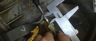
- Now calculate the amount of free play - if it is more or less than a segment of 125 - 135 mm, and after replacing the DS this will be the case, then it needs to be adjusted. The regulation process itself involves changing the length of the cable sheath.
- Open the hood and locate the end of the pedal cable. It is clearly visible, so finding it will not take much time. Using a wrench, loosen the locking nut securing the cable to the lever, and tighten the second nut. Do this until the pedal free play is in the range of 125 to 135 mm.
Measuring the travel distance from the pedal to the floor with a ruler
Measuring the travel distance with the pedal depressed
Adjusting the clutch drive with wrenches under the hood
If you have any questions regarding the process, we invite you to watch the video.
Replacing the clutch disc
Malfunctions of the driven disk are accompanied by slipping of the clutch and are manifested by the presence of a characteristic burning smell as the speed increases and slow acceleration. As well as increased vibrations and increased free play of the clutch pedal.
Materials, tools, replacement progress
The work is carried out in the presence of an inspection hole or overpass, which can, if necessary, be replaced with a winch or jack to lift the front of the car. You will also need to prepare a new clutch disc, a set of wrenches and a flashlight. If you have a hydraulic clutch, you should purchase brake fluid.
Replacement steps:
- depending on the design features of the vehicle, the starter, resonator, driveshaft and exhaust manifold are removed;
- the gearbox is dismantled to facilitate access to the clutch basket;
- The basket cover is removed and the disc is replaced.
It is also recommended to check the condition of the release bearing and replace it if necessary. The disk is installed with centering and good tightening of the basket bolts, which will prevent the formation of vibration when the vehicle is operating. After assembly, the brake fluid level inside the system is checked.
Removing the clutch
How to place the clutch disc correctly and which side to use is a question that often arises among novice motorists who do not pay attention to some nuances when performing work, ignoring which can lead to useless repairs and serious problems with the car.
When starting to remove the unit in question, the following requirements must be met:
- Stop the vehicle with special wedges;
- Release the cardan from the gearbox and the working cylinder;
- Disconnect the wiring limit switches for the reverse light switch;
- Using a spanner, unscrew a pair of fastening nuts that secure the gearbox cushion, which is removed. Next, you should remove the transmission box from the engine as far as possible so that the switch rests on the bottom;
- The transmission will end up hanging on the incoming muffler pipe, so it is advisable to secure the rear of the box by installing an additional support. After retracting the flywheel, you need to unscrew the six mounting bolts on the clutch basket. For ease of access to the fixing elements, the crankshaft should be rotated periodically;
- The disc is removed into the resulting groove by sliding the clutch basket. To remove the basket itself, you will need to move it towards the engine. Next, all that remains is to dismantle the fork and release bearing.
Replacing the clutch and fork on a Gazelle car with your own hands
- Replacing the Gazelle clutch
- Replacing the clutch fork
- Replacement video
Replacing the clutch of a Gazelle car is required quite often, as it is a vulnerable point. The machine is mainly intended for business, the components and assemblies of which always operate under load. Therefore, the service life of the parts is limited; on average, the clutch requires replacement every 50–70 thousand kilometers. As a rule, it changes as a set (pressure disk, driven disk, release bearing).
Gazelle business clutch replacement
Replacing the clutch of Gazelle business model cars is not difficult to do. To do this, you just need the appropriate tool. Work must be performed on a car lift or in a pit.
You can replace the disk or the entire set yourself. For example, let's take a Gazelle with a ZMZ 40524 engine (it is from the ZMZ 406 engine family).
We put the car in the pit and first of all remove the gearshift lever. Before removing the lever, it must be set to the neutral position. Raise the rubber casing.
We find the cone nut, unscrew it and pull out the lever.
We make marks on the driveshaft and rear axle shank.
Marks are made in order to place the shaft in the same position during assembly. If the “cardan” is not placed according to the marks, vibration may occur.
Then unscrew the gearbox yoke (8 bolts along the edges) and pull out the shaft. Before removing the driveshaft, it is advisable to drain the gearbox oil.
- We disconnect the wires going to the gearbox;
- We disconnect the fastening of the gearbox bracket to the exhaust pipe of the muffler;
- We completely remove the gearbox traverse, do this carefully, since the engine and gearbox will go down;
- Then we unscrew the nuts securing the gearbox itself and dismantle it.
We unscrew the fastening of the clutch slave cylinder, move the cylinder to the side, and remove the fork.
We dismantle the clutch housing (“bell”), first the lower aluminum housing amplifier, then the housing itself.
Unscrew the six bolts on the basket. Everything has been taken apart.
We take a new set - basket, disk, release bearing, and begin assembly. In order to install the gearbox without problems, the driven disk must be centered, and then the “basket” bolts must be tightened. The bolts need to be tightened evenly in a circle, and not immediately on one side. For alignment, you can use a special mandrel or any input shaft of the Gazelevskaya or Volgovskaya gearbox. The shaft will fit even a 4-speed gearbox.
Then we assemble everything further in reverse order. It is convenient to immediately put the release bearing on the flange of the input shaft of the box, having previously placed a sponge soaked in thick lubricant under it. The sponge can be soaked in transmission oil.
To fasten the gearbox yoke alone, you will need to jack up the gearbox; it is more convenient to do this operation together. After assembly, you should fill the gearbox with oil, checking the oil level using the control plug on the side. That's all - the clutch disc has been replaced.
Replacing the clutch fork
Replacing the clutch fork on the Gazelle Business model is very easy to do; you do not need to remove the gearbox for this. This type of repair can also be done by yourself.
How to make a quality replacement
Carrying out minor repairs, replacing the clutch fork, including adjusting its pedal, will not require much time. If there are high-quality parts, for example, made by Sachs or Kraft, the replacement will only take about 2 hours.
The Gazelle clutch requires proper handling and timely replacement as a result of frequent repairs and adjustments. Replacing the entire assembly is not necessary in every case. The stages of replacement depend on the brand of Gazelle car, determined by the engine, for example, Cummins ZMZ 406 and 405, etc.
The clutch kit must include a fork, a disc, a hydraulic hose, a hydraulic clutch, a clutch basket, a release bearing, the price of which from the manufacturer is lower than the cost of parts offered by chain stores. After diagnostics, it may be necessary to replace only the clutch slave cylinder, which operates under fairly high loads. In some cases, it is necessary to solve the problem with changing the gearbox, discovered as a result of system diagnostics.
Read more: Bolt with eccentric for camber adjustment
Sometimes it may be necessary to check the entire pipeline and also bleed the system. The cause of the violation may be damage to the reservoir included in the Gazelle clutch kit.
Causes of clutch failure
Replacing the clutch may be necessary as a result of intensive use of the Gazelle car and if the following errors occur:
The process of replacing the clutch on a Gazelle
- Low quality parts were used during assembly.
- The clutch pedal was kept depressed while driving, which is strictly prohibited by the manufacturers.
- There were “jerks” from a standstill at high speeds.
To increase the service life of the Gazelle clutch, installation of parts manufactured by the manufacturing company Sachs will be reliable. They are recommended by the manufacturer because they are reliable and have been tested for installation compatibility with the transmission and engine. Under the same conditions, the Sachs clutch, unlike parts from other manufacturers, will last longer. A common analogue of the Gazelle Business clutch, produced by Kraft, is not only of good quality, but also has a fairly low defect rate. The most common reasons why Gazelle owners contact service departments are malfunctions related to the clutch release drive. Among the main problems are:
- leak of the Gazelle clutch master cylinder (MCC);
- removal of brake fluid from the hydraulic fluid reservoir;
- Clutch slave cylinder (CLC) leak;
- bypass of the cuff of the central nervous system;
- bent or fallen out working cylinder rod, etc.
Careful operation of the car does not imply any “jerks”, but only the presence of conditions that allow you to move off smoothly and change gears while the car is moving. Most often, clutch replacement is required for trucks. A Gazelle car intended for business requires increased attention to this unit, the elimination of breakdowns in which is often not possible. Since replacing the device does not require removing the motor, you can repair the clutch or install new parts yourself.
Diagnostic principle and clutch replacement rules
Incorrect operation of the clutch system is determined by the following main points:
- noise is heard in the gearbox when the car is moving;
- the transmission turns off spontaneously;
- changing gears causes various extraneous noises;
- Changing gears is difficult.
Replacing the clutch fork
Replacing the clutch fork on the Gazelle Business model is very easy to do; you do not need to remove the gearbox for this. This type of repair can also be done by yourself.
To replace the fork, unscrew the two bolts of the clutch slave cylinder (CLC), the cylinder on the hose is moved to the side. We remove the old plug and install a new one. You need to make sure that the fork hits the special ebb of the release bearing clutch, otherwise the clutch pedal will not be pressed normally.
Having installed the new fork, we press the control center through the rod with our hands, bring it to the mounting points, and fix the cylinder with bolts. Of course, the clutch hose can be unscrewed and it will be easier to install the control unit, but then you will have to bleed the clutch. We have described replacing the plug in the simplest and most optimal way. » alt=»»> » alt=»»>
Source
Also check out
- Remove the 3rd transmission mounting bolt. Unscrew another nut located near the right CV joint.
- Remove the torque rod mounting bolts. There are 2 of them.
- Loosen the nut located on the box control drive rod clamp and remove the rod from the box.
- Place the support under the engine, unscrew the 2 nuts that secure the rear cushion (the purpose of this is to avoid a possible breakthrough of the hoses).
- Carefully remove the gearbox from the engine and release it to the floor. It should hang on the axle shafts.
- Alternatively, replace the clutch release bearing immediately.
- Assess wear, replace the disc, install a new clutch basket if necessary, check the paddles.
Assembly is performed in reverse order.
Thus, the installation of a new VAZ 2110 clutch without removing the box and draining the oil was successful.
Removing the clutch
How to place the clutch disc correctly and which side to use is a question that often arises among novice motorists who do not pay attention to some nuances when performing work, ignoring which can lead to useless repairs and serious problems with the car.
When starting to remove the unit in question, the following requirements must be met:
- Stop the vehicle with special wedges;
- Release the cardan from the gearbox and the working cylinder;
- Disconnect the wiring limit switches for the reverse light switch;
- Using a spanner, unscrew a pair of fastening nuts that secure the gearbox cushion, which is removed. Next, you should remove the transmission box from the engine as far as possible so that the switch rests on the bottom;
- The transmission will end up hanging on the incoming muffler pipe, so it is advisable to secure the rear of the box by installing an additional support. After retracting the flywheel, you need to unscrew the six mounting bolts on the clutch basket. For ease of access to the fixing elements, the crankshaft should be rotated periodically;
- The disc is removed into the resulting groove by sliding the clutch basket. To remove the basket itself, you will need to move it towards the engine. Next, all that remains is to dismantle the fork and release bearing.
Features of clutch disc installation
Installing the clutch disc has several features.
Disc alignment
The clutch disc must be strictly aligned with the axis of the flywheel and input shaft. Even small deviations are unacceptable. When installing the gearbox, the input shaft must simultaneously enter the clutch disc splines. And into the crankshaft support bearing. To do this, the disk is aligned along the axis of rotation. For this, a guide shaft is used. The diameter of the shaft corresponds to the diameter of the clutch disc splines. And at the end it has a seat with the diameter of the crankshaft bearing. After the shaft aligns the splined part and the bearing of the shaft knees along the axis of rotation. The clutch basket is tightened. If you don't do this. Then when installing the gearbox. Once the input shaft gets into the splines, it will not be able to get into the bearing of the shaft knees.
There are clutch mechanisms with two discs. In this case, the centering shaft must have a splined part like the gearbox input shaft. Because it is necessary to center the two disks relative to the support bearing of the shaft knees. Therefore, a used gearbox input shaft of the same model is used as a guide shaft. Correct alignment of the discs greatly simplifies the installation of the gearbox.
Disc direction during installation.
The disc must be installed correctly towards the gearbox and engine flywheel. Installation is possible in both directions. He presses the clutch basket. And until the car starts moving, you may not even be aware of the error.
By design, the disk has a mechanism consisting of springs. Springs soften the effect of angular loads on the disk. This mechanism has a protrusion from the plane of the disk. The larger one is in one direction. Different designs of clutch mechanisms suggest that this protrusion faces either the flywheel or the clutch basket. On passenger cars, the protrusion faces the clutch basket and fits into it. If the disk is turned the other way, it will rest against the flywheel mounting bolts.
When moving away, the disc will simply crumble.
On a car with two clutch discs. The disks are either identical or facing different directions from each other. Or there is disk No. 1 and disk No. 2. You can determine which side the clutch disc is installed on using the drawing or instructions.
Modern spare parts indicate the direction of the disk location. Therefore, it is necessary to carefully inspect the disk. And read the inscription on it how to install the clutch disc. Usually it is in English. For example, on a Mercedes car the direction is indicated flywheel side. What does flywheel side mean?
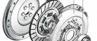
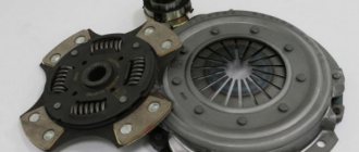
Functions and structure of the clutch disc
Which on-board computer to install on the Lada Kalina
On the side of the casing there are three evenly spaced recesses in the shape of a rectangle. Three pressure plate hubs fit tightly into them. This structure guarantees the transmission of torque to the working disk and the ability to move it relative to the axis when the clutch is activated.
Between the pressure disk element and the casing there are 18 springs, placed in pairs, which have versatile curls to prevent the part from jamming. To counteract distortion of the working disk and obtain optimal force, spring elements are placed from the same group. The springs are protected from excessive heating in the event of clutch slipping by washers made of heat-insulating pressed asbestos material.
Spherical nuts with conical springs are attached to the ends of the tail forks of the unit in question, providing some rolling of the element required to dampen the change in the distance between the axles when the disk is retracted. In the grooves of the protrusions of the guide disk element there are three steel levers, which are connected to the disk and support forks by means of needle-type bearings and axles.
VAZ 2106 clutch replacement
- home
- About company
- Services Engine repair
- Suspension repair
- Repair, replacement of clutch
- Steering rack repair
- Brake system repair
- Cooling system repair
- Muffler repair
- Replacing timing belts
- Change of oil
- Manual transmission repair (DSG)
- Changing the gearbox oil
- Cleaning the injector and nozzles
- Computer diagnostics
- Refilling car air conditioners
- Auto electrician
- Installation of parking sensors
- Car alarm installation
- Car audio installation
- Xenon installation
- Tire service. Wheel repair and replacement
- Disc rolling
- Seasonal wheel storage
- Wheel alignment 3D
- Post-warranty maintenance
- Checking the car before purchasing
- Guarded parking lot
BRANDS
- Audi repair
KIA repair Toyota repair BMW repair Hyundai repair Mercedes repair Mazda repair Chevrolet repair Skoda repair Suzuki repair Nissan repair Mitsubishi repair Volvo repair Ford repair Volkswagen repair Citroen repair Peugeot repair Renault repair VAZ repair Ford repair Opel repair Honda repair Subaru Repair Lexus Repair Land Rover repair Porsche Repair SsangYong Repair Chery Prices Vacancies Promotions Tips Contacts
- Sign up
- Live chat
- home
- About company
- Services Engine repair
- Suspension repair
- Repair, replacement of clutch
- Steering rack repair
- Brake system repair
- Cooling system repair
- Muffler repair
- Replacing timing belts
- Change of oil
- Manual transmission repair (DSG)
- Changing the gearbox oil
- Cleaning the injector and nozzles
- Computer diagnostics
- Refilling car air conditioners
- Auto electrician
- Installation of parking sensors
- Car alarm installation
- Car audio installation
- Xenon installation
- Tire service. Wheel repair and replacement
- Disc rolling
- Seasonal wheel storage
- Wheel alignment 3D
- Post-warranty maintenance
- Checking the car before purchasing
- Guarded parking lot
BRANDS
- Audi repair
KIA repair Toyota repair BMW repair Hyundai repair Mercedes repair Mazda repair Chevrolet repair Skoda repair Suzuki repair Nissan repair Mitsubishi repair Volvo repair Ford repair Volkswagen repair Citroen repair Peugeot repair Renault repair VAZ repair Ford repair Opel repair Honda repair Subaru Repair Lexus Repair Land Rover repair Porsche Repair SsangYong Repair Chery Prices Vacancies Promotions Tips Contacts
Spare parts for trucks
Full model range: GAZ-3307, 53, GAZ-3309, GAZ-66, 3308, 33081, 33086, GAZ-33104
Car clutch GAZ-3309, GAZ-3308, GAZ-33081 Sadko for diesel engine
The clutch of the GAZ-3309, GAZ-3308, GAZ-33081 Sadko (diesel engine D-245) is permanently closed, single-disk, dry, with a central pressure diaphragm spring and a damper device on the driven disk. Pressure disk 19 (Fig. 1) is connected to casing 10 by three groups of plates.
The clutch and release mechanism of the GAZ-3309, GAZ-3308, GAZ-33081 Sadko are located in the clutch housing 21, which is attached to the rear sheet of the engine with ten nuts 16 studs and a bolt, under which conical spring washers 15 are installed with the convex side to the nuts and the bolt head.
Centering the clutch housing relative to the axis of the engine crankshaft is carried out using two pins 20 pressed into the clutch housing. On the clutch housing there are 6 brackets for the rear engine mounts, which are secured with 5 bolts.
Rice. 1. Clutch GAZ-3309, GAZ-3308, GAZ-33081 Sadko (diesel engine D-245)
1 flywheel; 2, 5 - bolts; 3 - fork; 4 — rear cushion; 6 — rear engine mount bracket; 7 — protective ring; 8 — clutch; 9 — rivet of the friction lining; 10 - casing; 11 — support ring; 12, 20 — pins; 13 - bearing; 14 — gearbox input shaft; 15 — washer; 16 - nut; 17 — driven disk; 18 — disc pressure spring; 19 — pressure disk; 21 — clutch housing
There is no gap between the pressure spring 18 and the clutch bearing 8, so the inner ring of the bearing rotates at the engine crankshaft speed. During operation, the clutch does not require adjustments.
The clutch control drive for GAZ-3309, GAZ-3308, GAZ-33081 Sadko is hydraulic. The clutch master cylinder 15 (Fig. 2), mounted on the front panel of the cab, is actuated by the suspended pedal 20.
The master cylinder of the GAZ-3309, GAZ-3308, GAZ-33081 Sadko clutch is connected by a hose 2 to one of the sections of the three-section supply tank 1, equipped with an alarm sensor for an emergency drop in the brake fluid level (the other two sections of the tank supply the hydraulic drive of the dual-circuit service brake system).
Rice. 2. Clutch drive of GAZ-3309, GAZ-3308, GAZ-33081 Sadko cars
B - compensation hole; G - bypass hole; 1 - supply tank; 2 - supply hose; 3, 18 — fittings; 4, 23 — protective caps; 5, 24 — pushers; 6.33 — bushings; 7.34 - pistons; 8 — piston valve; 9, 14, 35 — cuffs; 10.32, 37 — springs; 11 - coupling; 12 - nut; 13 — thrust washer; 15 — clutch master cylinder; 16 — clutch master cylinder valve; 17 — thrust ring; 19 - pipeline; 20 - pedal; 21 - hose; 22 — clutch slave cylinder; 25 - cover; 26 — fork ring; 27 — fork support axis; 28, 30 — rollers; 29 - coupling pin; 31 — clutch bearing; 36 — spacer sleeve
The working cylinder 22, mounted on the upper part of the clutch housing, is connected to the main cylinder by a pipeline 19 and a hose 21, and is equipped with a valve to remove air from the hydraulic system. When the pedal is not pressed, the cavity under piston 7 of the main cylinder is connected to the reservoir through compensation hole B, which eliminates an increase in pressure in the hydraulic system and clutch slipping.
The bearing 31 of the GAZ-3309, GAZ-3308, GAZ-33081 clutch release clutch is pressed against the pressure spring with a force of 70-100 N (7-10 kgf) using spring 32 through piston 34, pusher 24, fork 3 (see. Fig. 1) and clutch 8. When the clutch linings wear out under the action of the pressure spring, the system takes a new position, compressing spring 32 (Fig. 2).
Excess fluid from the clutch slave cylinder GAZ-3309, GAZ-3308, GAZ-33081 Sadko enters the reservoir through a pipeline into the compensation hole in the master cylinder.
The existing bend in the length of the working cylinder for the movement of the piston provides (without adjustment) the calculated wear of the clutch linings. The position (travel) of the clutch pedal relative to the floor is regulated by changing the length of pusher 5. Repair work on the clutch can be carried out without removing the engine from the car.
Removing the clutch of a GAZ-3309, GAZ-3308, GAZ-33081 Sadko car
To remove the clutch, you must remove the gearbox and clutch housing.
To remove the clutch housing GAZ-3309, GAZ-3308, GAZ-33081 Sadko, you must do the following:
— disconnect the exhaust system pipe from the clutch housing; — Unscrew the fastening bolts and remove the cover of the clutch slave cylinder; — unscrew the nuts of the studs securing the clutch working cylinder, lift up the working cylinder assembled with the pusher, without disconnecting the hose;
ZIL clutch maintenance
The single-plate clutch on a car is not adjustable. If necessary, the clutch is removed and adjusted.
Clutch maintenance includes cleaning from dirt and timely tightening the bolts securing the clutch housing to the cylinder block. These bolts are tightened (tightening torque 8-10 kgm). The bolt heads are secured with plates, the ears of which are bent to the edge of the bolt.
Caring for the clutch drive involves adjusting the free play of the pedal by changing the length of the rod. The clutch release bearing does not require lubrication during operation. The fork axles and clutch release pedal are lubricated according to the lubrication chart. See the figure for adjusting the clutch release drive.
When is it necessary to replace the clutch disc?
This element has a long service life and, with careful driving, can last a long time. The following signs indicate its malfunction:
- It is not possible to turn on any of the speeds;
- When switching gears, extraneous noise and crunching occurs;
- When you press the pedal with your foot, it falls through;
- The car loses traction;
- Slippage occurs.
Need a clutch repair? You will find all the necessary components in the Tekhnichka-Express online store. We offer a large selection of spare parts for trucks and cars at low prices.
Replacement
{banner_content}Assembly of the unit is carried out in a mirror disassembly sequence. First, apply a special lubricant to the bearing hole of the gearbox input shaft, and clean the friction area and the pressure disk with a cloth. Installing the disk in its place is done with the protruding part facing the basket. Pre-applied marks on the housing and flywheel are aligned to prevent imbalance.
During the work, it is necessary to center the driven disk in relation to the crankshaft axis. For this procedure, a special rule is used (simulates the splined part of the input shaft), which should be easily removed after installation. The fastening bolts must be tightened alternately with even force to prevent the casing from moving.