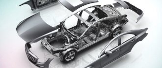
Operating principle of clutch actuators
The clutch master cylinder works as follows.
When you press the pedal 21, the pusher 14 moves the piston 4, compressing the spring 8. As soon as the cuff 10 closes the bypass hole b, pressure is created inside the cylinder in cavity a, and the liquid passes through the hole in the fitting 7 and through the connecting tube 2 into the working cylinder 29, causing movement of the piston 36, pusher 27 and associated with it through the tip 24 and pin 23 of the clutch release fork 22. The clutch disengages. At the same time, the tension spring 25 of the fork is stretched and the pressure springs 14 are compressed.
When the clutch pedal is released, the latter returns to its original position by spring 75, and the piston 12 of the master cylinder, under the action of the return spring 8, moves after the pusher 17 until it stops against the washer 14. At the same time, the pressure in the system drops, and the clutch pressure plate changes under the action of the pressure springs , presses the driven disk against the flywheel again.
Next, the thrust bearing and the associated clutch release fork move under the action of the tension spring 25, which constantly presses the pusher rod 27 against the piston 36 and moves the latter to its extreme forward position. In this case, the piston displaces liquid from the internal cavity of the working cylinder 29.
When the clutch pedal is abruptly released, the fluid returning from the working cylinder to the main cylinder does not have time to fill the space vacated by piston 12, and a vacuum is created in cavity a.
Under the influence of this vacuum, liquid from cavity e (where it enters through hole c) flows into cavity a through holes d in the piston head, pushing back valve 11 and the edges of cuff 10. Grooves on the surface of cuff 10 facilitate the passage of liquid from cavity d to cavity a. Subsequently, as it enters the pipeline, excess liquid is forced out of cavity a through compensation hole b into tank 3.
The principle of operation of the car's clutch drive, with which the force from the pedal is transmitted to the shift mechanism, can be mechanical, hydraulic or electric.
The mechanical clutch drive is structurally the simplest: it consists of a steel cable connecting the pedal rod and the clutch lever. There is usually a threaded connection on it, which can be used to adjust the length of the cable. The disadvantage of this drive is that it requires more force when pressing the pedal.
The hydraulic drive is more comfortable to use, especially if you have to use the clutch frequently. Its operating principle is similar to the operation of the brake system: when you press the pedal, the piston presses on the fluid, which, moving in the cylinder, sets the clutch lever pusher in motion. In this case, the pedal stroke is softer, but you need to monitor the condition of the hydraulic hoses and control the level and quality of the hydraulic fluid poured into the system.
The electric drive differs from the mechanical one in that the clutch release cable is driven by an electric motor, which is activated when the pedal is pressed. Otherwise, its design is not much different from a mechanical drive.
The following main parts are involved in the operation of the clutch assembly:
- a flywheel rigidly mounted on the crankshaft of the power unit;
- 2 disks - pressure and driven, making up the friction mechanism;
- casing;
- compression springs;
- bearing;
- diaphragm spring in the form of concentric arms;
- fork;
- hydraulic drive working cylinder, activated when the pedal is pressed.
The most primitive mechanism, which was used in the last century, did not include a hydraulic cylinder, which greatly facilitated the driver’s work. Instead, there was a mechanical cable drive.
The drive disk (aka basket) is bolted to the flywheel and rotates with it. The normal state of the clutch when the pedal is in the depressed position is “engaged”. That is, the crankshaft of the motor and the primary gearbox are connected by means of a disk pressed to the plane of the flywheel by a spring. When you press the pedal, the unit works according to the following algorithm:
- Through the brake fluid, the force is transmitted to the hydraulic cylinder, which pushes the fork.
- The fork presses on the bearing, and it pushes concentric arms, whose ends rest against the pressure plate.
- The ends of the levers are pulled back and release the disk, as a result the connection between the shafts is broken, while the rotating crankshaft does not turn the gearbox gears.
- When you need to move away, you gradually release the pedal. The bearing releases the levers, which, under the influence of springs, press on the disk. The latter is pressed against the flywheel by the friction surface and the car moves smoothly forward.
- The algorithm is repeated with each gear change.
To make the coupling of the engine and transmission smoother, the clutch device provides several damper springs inside the driven disk. When the friction linings touch the flywheel surface, they compress and further smooth out the transmission of engine power.
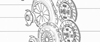
In the time that has passed since the creation of the first clutch, the design of this element has undergone significant changes. Today, many manufacturers use custom designs that match the characteristics of the engines and gearboxes installed on their vehicles. However, the basic design of clutches of any brand includes the same set of components:
Flywheel (1) – the drive disk in the clutch mechanism, is located directly on the engine crankshaft. Most modern cars use a dual-mass flywheel, which is formed from 2 separate discs connected by springs. One half of this type of flywheel is connected to the crankshaft, the second to the driven disk. The spring connection of the 2 halves ensures smoothing of jerks, dampening of vibrations, and smooth transmission of torque to the gearbox.
- Clutch basket (3) - its design includes a concave housing, which is why this part is called “basket,” as well as a pressure plate connected to the housing by a spring connection. Thanks to a system of pressing springs, the pressure plate is connected to the driven one, due to which torque is transmitted.
- Clutch disc (2) – installed between the pressure plate and the flywheel. This element is connected to the gearbox input shaft by the hub. The design of this disc is prefabricated; it consists of a metal base, friction linings, as well as spring-dampers that absorb shock and ensure smooth transmission of torque.
- Push clutch (4) paired with a release bearing - when the driver depresses the clutch, the bearing presses on the diaphragm spring and compresses it. Thanks to the presence of a bearing, the push clutch does not come into contact with the moving elements of the clutch and does not wear out.
Also an important element of the clutch is the drive system: friction, hydraulic or electromagnetic.
If you do not know how the clutch works, then our article will help you understand this issue. Let's look at how a car's clutch works in practice.
If the clutch is released, the driven shaft is at this time clamped between the pressure plate and the flywheel. When the driver presses the gas, friction occurs in the system, as a result of which torque is redirected from the flywheel of the internal combustion engine to the power speed of the vehicle. When the driver presses the CC pedal, the parts of the unit begin to function and interact with each other.
As a result, the driven shaft is released from the clamping force. For this to happen, the device’s cable comes into play. The release bearing is acted upon by the release fork of the mechanism, as a result of which the bearing begins to move towards the flywheel along the shaft. The bearing then exerts pressure on the pressure spring plates.
In the event that the petals of the spring of the mechanism bend towards the flywheel, the spring bends the outer edge from the pressure plate, thus releasing it. At the same time, tangential springs release the pressure plate, as a result of which torque is no longer transmitted from the engine to the gearbox.
Read more: Mechanical engine supercharger
If the driver releases the pedal, the pressure plate begins to interact with the driven pulley through a diaphragm spring. It is also worth noting that the pressure plate interacts with the flywheel when the pedal is released. Then the torque begins to be transmitted from the engine to the gearbox as a result of the generated friction forces.
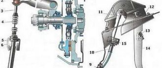
Diagram of the mechanism with the designation of each element
Next, we will look at the diagram of the device and also tell you what parts it consists of.
- 1 — the sheath of the mechanism cable itself;
- 2 — lower part of the shell, tip;
- 3 — pedal cable fastening device;
- 4 — cable protective cover;
- 5 — lower part of the cable;
- 6 — nut that allows you to adjust the position of the pedal;
- 7 - lock nut;
- 8 — cable lead;
- 9 — mechanism shutdown fork;
- 10 — protective casing of the device;
- 11 — fastening screw;
- 12 — pressure disk;
- 13 — unit flywheel;
- 14 — driven pulley;
- 15 — primary pulley of the power unit;
- 16 - lower part of the device housing;
- 17 - the mechanism housing itself;
- 18 — spring of the pressure device;
- 19 - bearing designed to turn off during gear shifting;
- 20 — coupling flange;
- 21 — clutch sleeve of the release element;
- 22 — rubber seal;
- 23 — upper part of the cable sheath;
- 24 — upper part of the cable;
- 25 — supporting part for fastening the pedal of the device;
- 26 — mechanism pedal spring;
- 27 - the pedal itself;
- 28 - thrust plate.
The principle of operation of a car clutch is to smoothly connect and disconnect two metal discs: one is rigidly attached to the engine shaft, and the second to the gearbox.
The clutch mechanism is activated by a cable leading from the pedal into the engine compartment of the car directly to the clutch mechanism itself. When the pedal is pressed, the engine and transmission are disconnected.
What does a clutch consist of?
In order not to break the clutch, you need to know not only how it works superficially and what its functions are, but also what parts it consists of. The main components include the driven and driven parts, the shutdown mechanism and the pressure system.
The engine rotational torque is transmitted from the flywheel to the drive parts, which in turn transmit torque to the gearbox drive shaft. The frictional moment is provided thanks to a pressure mechanism, which, thanks to the tight coupling of the driven and driven parts, gives the long-awaited result of movement.
Disengaging the clutch is considered important. So one disk, on which springs are located peripherally, is located in a cast-iron crankcase, which in turn is located in the engine block crankcase.
The drive part includes the clutch housing and flywheel, the latter in turn is attached to the crankshaft flywheel using six special bolts. The pressure plate is located in the middle part of the casing. The torque of the pressure plate is transmitted from the flywheel through three protrusions that are located in the disk and enter the casing windows. The driven disk, hub, and drive shaft of the gearbox are the main and mandatory components of the driven part of the clutch.
On both sides of the driven disk there are friction linings made of a copper-asbestos composition (or another metal-asbestos composition), which can withstand unusually high temperatures and are known for their friction properties. The driven disk is connected to the hub with rivets or through springs. These springs are an integral part of the spring-friction damper of rotating vibrations (that is, the damper)
CLUTCH MECHANISM
Clutch mechanism
is a device in which torque is transmitted due to the work of friction forces. The clutch mechanism allows you to briefly separate the engine and gearbox, and then smoothly connect them. The elements of the mechanism are enclosed in a clutch housing, which is attached to the engine crankcase.
The clutch mechanism consists of
:
- crankcase and casing,
- drive disk (which is the engine flywheel),
- pressure plate with springs,
- driven disk with wear-resistant linings.
The driven disk is constantly pressed against the flywheel by the pressure disk under the influence of strong springs. Due to the enormous frictional forces between the flywheel, driven and pressure plates, they all rotate together when the engine is running. But only when the driver does not touch the clutch pedal, regardless of whether the car is moving or standing still.
To start the machine moving, it is necessary to press the driven disk connected to the drive wheels to the rotating flywheel, that is, engage the clutch.
And this is a difficult task, since the angular speed of rotation of the flywheel is 20 - 25 revolutions per second, and the speed of rotation of the drive wheels is zero. Clutch engaged
In the first stage
work to engage the clutch - slightly release the pedal, i.e. We allow the springs of the pressure plate to bring the driven disk to the flywheel until they lightly touch. Due to frictional forces, the disk, slipping for some time relative to the flywheel, will also begin to rotate, and the car will slowly crawl.
At the second stage
– we hold the driven disk from any movement, i.e. hold the clutch pedal in the middle position for two to three seconds so that the speed of rotation of the flywheel and disc is equal. At the same time, the machine increases its speed.
At the third stage
— the flywheel, together with the pressure and driven disks, already rotates together without slipping and at the same speed, transmitting 100% torque to the gearbox and then to the drive wheels of the car. This corresponds to the state of the clutch mechanism - engaged, the car is moving. Now all that remains is to completely release the clutch pedal and remove your foot from it.
If you release the clutch pedal sharply when starting to move, the car will “jump” forward and the engine will stall.
To release the clutch
The driver presses the pedal, and the pressure plate moves away from the flywheel and releases the driven disk, interrupting the transmission of torque from the engine to the gearbox.
Press the clutch pedal fairly quickly, but not abruptly, with a calm movement until the end of the pedal stroke. The clutch is disengaged
after mastering the operation of the clutch pedal in three stages
Drive purpose
Everything is simple here. The device is designed to engage and disengage the clutch by pressing the diaphragm spring.
The clutch, or coupling, is an integral part of any vehicle. It is this device that takes on the key loads and impacts. The unit is a power clamping device that transmits a rotational impulse between the main parts of the car: the transmission and the engine. A node is formed from a small number of disks.
The automatic clutch is aimed at temporarily separating the gearbox from the engine and connecting them softly. The need for smooth lapping appears while the car is running. Transitional disconnection of the engine and gearbox (gearbox) is important both when further switching speed modes, and when immediately braking or stopping the car.
Important! The load on the clutch increases during braking, when it is turned on abruptly, as well as when the car hits an uneven road surface.
While the vehicle is running, the coupling system is generally in the engaged position. It serves as a power transmitter from the engine to the gearbox, and also protects the parts of the latter from a variety of intense actions that occur in the transmission.
Mechanical drive device
As already mentioned, the mechanical drive has an extremely simple structure and consists of the following structural elements:
- clutch pedal;
- cable;
- regulation device;
- lever drive;
- release bearing.
The main element of the mechanical drive is a flexible cable enclosed in a sheath. The drive pedal is located inside the car and is connected to the lever device (clutch fork) through a flexible cable. At the connection of the clutch cable and fork there is an adjusting device designed to set the free play of the pedal. The operation of a mechanical drive is extremely simple: the driver, by acting on the pedal, sets in motion a lever device, which in turn moves the release bearing along the guide, thereby disengaging the clutch.
Classification
The clutch is systematized according to several functional devices.
Based on the contact between passive and active elements, the following categories of nodes are distinguished:
- Hydraulic.
The work is carried out due to the flow of a special suspension. Similar clutches are used in automatic transmissions. 1 – hydraulic clutch/brake master cylinder reservoir; 2 – liquid supply hose; 3 – vacuum brake booster; 4 – dust cap; 5 – brake servo bracket; 6 – clutch pedal; 7 – bleeding fitting of the clutch master cylinder; 8 – clutch master cylinder; 9 – nut securing the clutch master cylinder bracket; 10 – pipeline coupling; 11 – pipeline; 12 – gasket; 13 – support; 14 – bushing; 15 – gasket; 16 – bleeding fitting for the clutch slave cylinder; 17 – clutch slave cylinder; 18 – nuts for fastening the working cylinder bracket; 19 – clutch housing; 20 – flexible hose coupling; 21 – flexible hose - Electromagnetic. Magnetic flux is used for actuation. Installed on small cars.
- Frictional or typical.
The impulse is transmitted due to the friction force. The most popular type for cars with a manual transmission. 1.* Dimensions for reference. 2. Tightening torque of the crankcase mounting bolts 3. The vehicle’s clutch release drive must provide: 1. Movement of the clutch to disengage the clutch 2. Axial force on the thrust ring when the clutch is not disengaged 4. In view A-A, the clutch and gearbox housing are not shown
Important! Due to the complexity of the device, electromagnetic and hydraulic couplings have not become widely used.
By type of creation
In this category, the following types of coupling are distinguished:
- centrifugal;
- partially centrifugal;
- with main spring;
- with peripheral spirals.
Based on the number of driven shafts there are:
- single-disk - the most common type;
- double-disc - installed on heavy-duty freight vehicles or buses;
- multi-disc - used in motorcycles.
By drive type
According to the category of the clutch drive, they are classified into:
- Mechanical.
They provide for the transmission of impulse when pressing the lever through a cable to the release fork. 1 — fixing clip; 2 — mechanism for adjusting the free play of the pedal; 3, 4 — sealing washers; 5 - bushing; 6 — clutch pedal; 7 — cable clutch pedal bracket; 8, 9 — fastening bolts; 10 — lever; 11 — lock washer; 12 - sealing washer; 13 - toothed washer; 14 - spring; 15 — pusher; 16 — supporting element; 17 — shell stop - Hydraulic. They include the clutch master and slave cylinders, which are connected by a high-pressure tube. When you press on the pedal, the key cylinder rod on which the piston is placed is activated. In response, it puts pressure on the running fluid and creates a press that is transmitted to the main cylinder.
Did you know? In a car with an automatic transmission there is no clutch pedal. But this only means that the coupling operates without human intervention.
There is also an electromagnetic type of coupling, but today it is practically not used in mechanical engineering due to expensive maintenance.
Car clutch device
Clutch is a mechanical device that transmits torque from the engine to a manual transmission (manual gearbox) based on sliding friction and is capable of briefly interrupting the transmission of torque from the engine to the manual transmission.
The main elements of the clutch are:
Flywheel. Clutch basket (drive plate or pressure plate).
Clutch disc (driven disc).
Clutch drive parts:
Clutch pedal. The force from pressing the clutch pedal onto the clutch basket can be transmitted in various ways:
— hydraulic drive (there is a clutch master cylinder, a clutch hose or tube, a clutch slave cylinder, a clutch fork, a release bearing). Some cars have a vacuum clutch booster, and sometimes the clutch slave cylinder is combined with the release bearing, but there is no clutch fork.
— a mechanical drive involves the transmission of mechanical force from the pedal to the fork through cables or a system of levers. — pneumatic drive (includes almost the same elements as the hydraulic drive, only the working fluid in the system is not brake fluid, but compressed air). — electromechanical drive (there is a clutch pedal position sensor, an electronic control unit, an actuator (solenoid, electromagnet) for the fork drive). — combined systems (combine elements of several systems).
Classification
By the number of driven discs: - single-disc (the most common type of clutch). — double-disc (used on large trucks, special equipment, sports cars).
— multi-disc (motor vehicles, special equipment).
By control method: - mechanical (used on small cars or very old cars). — hydraulic (the most common option). — pneumatic (used on large trucks and special equipment). — electric (often found on modern cars with a robotic gearbox).
- combined systems.
By type of friction: - dry (the most common type)
— oil (motor vehicles)
Flywheel
The flywheel is a massive metal disk. In the center of the disk there are several circularly located holes intended for attaching the flywheel to the crankshaft. There is a hole in the center of the flywheel for a bearing or flywheel bushing. The free end of the manual transmission input shaft is inserted into this bearing. Along the perimeter of the flywheel there is a gear ring - a crown. The crown is necessary to connect the starter bendix with the crankshaft flywheel.
Clutch basket (drive plate or pressure plate)
There are two main types of clutch basket designs: 1. Clutch baskets with a diaphragm spring 1.1. Direct spin. 1.2. Reverse spin.
2. Spring-lever type clutch baskets
The main elements of baskets with a diaphragm spring are: - Pressure disk (is a massive steel disk, one surface of which is smooth and is intended for contact with the friction lining of the driven clutch disk, and the other surface is uneven and has various protrusions and indentations and is intended for articulation with the basket casing).
Clutch release drive device
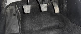
The stamped clutch pedal 21 is mounted on a welded bracket 12, fixed to the body with bolts 11 and studs 8 with nuts 7. The clutch pedal swings on an axis 16, which is fixedly fixed in the bracket 12. The pedal is secured against rotation by a flat that fits into a shaped hole in one of the cheeks pedal bracket.
The axial movement of the axis is limited by the cotter pin 13 and the shoulder of the flat. Two polyamide bushings 17 rotating on an axis, having collars at one of the ends, are inserted into the pedal hub.
The bushings have high wear resistance and do not require lubrication during operation. A rubber pad 31 is put on the pedal platform. The pedal is held in its original (rearmost) position by the force of the tension spring 15. In this case, the non-adjustable pusher 14, pivotally connected to the pedal with a pin 19, rests against the limiting washer 5, fixed in the axial direction with a locking ring.
In the initial position of the pedal, the piston 12 of the clutch master cylinder under the action of the spring 8 abuts its end against the washer 14. Between the pusher 14 and the piston 4 there is a constant gap of a = 0.2 - 1.0 mm, which is ensured within the specified limits by the selected dimensions of these parts and the limiting washers 5.
Read more: Auto electrician tools and equipment: do-it-yourself LED probe (tester) || Auto electrician tools and equipment DIY LED probe tester
The specified gap provides the piston of the master cylinder with the opportunity to take its original position (with the clutch engaged), guaranteeing communication between cavity a of the cylinder and the filling tank 3 through compensation hole b.
In clutch and foot brake control drives, pedal axles, polyamide bushings, pushers, pedal linings and fasteners are interchangeable. The clutch master cylinder is designed to create pressure in the hydraulic clutch drive system. The cylinder has a cast iron body 9 with an internal diameter of 22 mm with a figured flange;
Two pins 18 are screwed into the flange, with the help of which the cylinder and pedal bracket 12 are attached to the front panel of the body. During assembly, up to four (as needed) adjusting shims 6, made of sheet steel 0.5 mm thick each, are installed between the cylinder body flange and the front body shield.
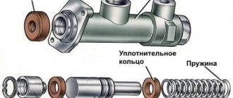
At the top of the master cylinder body there is a tank 3 made of translucent plastic. The reservoir contains a certain supply of brake fluid necessary for the normal operation of the hydraulic clutch drive. The tank is closed with a plastic threaded cap 1, in which there is a hole to communicate the internal cavity of the tank with the atmosphere, and a reflective plate is attached to prevent the brake fluid from splashing out through the specified hole.
The nutrient tank 3 is attached to the main cylinder body 9 with a threaded fitting 4, which has a slot at the end for a screwdriver. The sealing gasket 5 after tightening the fitting guarantees the tightness of the connection between the tank and the cylinder body. Through the hole in fitting 4, brake fluid from reservoir 3 flows by gravity into housing 9 of the master cylinder.
A rubber sealing collar 13 is placed on the piston 12 located inside the cylinder, which prevents liquid from leaking out of the cylinder. The piston is cast from zinc alloy. There are six through holes in the piston head, covered with a thin steel ring-valve 11 and an internal working rubber cuff 10.
A rubber protective cap 16 protects the internal cavity of the cylinder from dust. The cap is tightly placed on the groove in the cylinder body and the pusher rod 17.
The clutch slave cylinder 29 is secured with two studs 30 and nuts 28 on the left side of the clutch housing. The internal diameter of the working cylinder is 22 mm.
The main and working cylinders are connected to each other by a bent copper (6×1 mm) or two-layer steel tube 2 with copper-plated inner and outer surfaces (6×0.7 mm). The spiral located in the middle part of the tube compensates for the change in the distance between the ends of the tube, which is inevitable when the position of the power unit, suspended on rubber cushions, changes relative to the body.
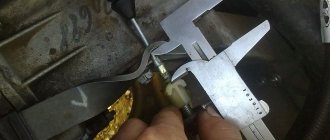
In addition to being secured at the ends, the tube has two intermediate attachment points: on the left mudguard of the body using bracket 1 and on the engine crankcase using bracket 42. Rubber gaskets 43 are laid between the fastener and the tube. The ends of the tube have a double conical flaring, the shape and dimensions of which shown in the figure. Before flaring the ends, connecting nuts are put on the tube, with which it is then connected to the main and working cylinders.
The housing 3 of the working cylinder is a casting made of gray cast iron, having on one side an open cylindrical cavity into which a cast aluminum piston 7 with a rubber sealing collar b, a spacer fungus 5 and a spring 4 are inserted. The spring constantly presses the spherical surface of the fungus against the sealing edge of the cuff and through it the edge to the cylinder mirror, which significantly improves the seal of the working cylinder, especially when there is no pressure in the system (the clutch is engaged).
The conical valve 2 screwed into the cylinder body 3 serves to remove air from the hydraulic drive system. Rubber cap 1 is placed on the valve head and protects the internal channel of the valve from clogging.
A pusher 27 is inserted into the spherical recess of the piston 36, which is adjustable in length. The pusher is adjusted by screwing it in or out of the fork tip 24. The position of the tip is fixed by the lock nut 26. The spring 25 of the clutch release fork 22 constantly presses the pusher to the spherical surface of the piston and, in the absence of pressure in the clutch hydraulic drive system, moves the piston to the extreme forward position.
Since the piston 36 in the cylinder 29 can move in the direction corresponding to the clutch disengagement (to the right in the figure) only under the influence of the working fluid pressure, the formation of vacuum is eliminated, and therefore the penetration of air into the cylinder through leaks in the piston. Therefore, there is no need to maintain excess pressure in the connecting tube 2 and in front of the piston 36, which is usually provided by installing a double valve in the master cylinder, as is done in the hydraulic brake drive (see below).
All parts of the clutch master cylinder, with the exception of housing 9 and fitting 7, are interchangeable with the corresponding parts of the brake master cylinder. Since the clutch master cylinder does not have a double valve, the body and fitting of this cylinder are different from the body and fitting of the brake master cylinder.
With this constructive solution, the force is transmitted in a different way. The hydraulic drive circuit does not require a cable; the implementation of a mechanism with this type of control is a little more complicated and the cable is replaced by a hydraulic line. The force is transmitted through an incompressible fluid passing through the line, and since the hydraulic drive is similar to that used in the brake system, the same fluid is used for operation. The clutch device, controlled by a hydraulic drive, includes the following elements:
- Pedal.
- The main cylinder, consisting of a piston with a pusher, a fluid reservoir and sealing collars.
- The slave cylinder has a similar design.
- The line connecting the cylinders.
- Liquid reservoir.
- Additionally, the cylinders are equipped with valves to remove air from the system.
Bleeding the clutch
If you briefly familiarize yourself with the clutch bleeding algorithm, it happens as follows:
- Preparing the system for operation.
- Connecting a rubber hose to the fitting.
- Press the clutch and drain the fluid until all air comes out.
To bleed the hydraulic clutch, you will need the following tools:
- Tool for fixing the clutch pedal.
- Canister for draining brake fluid.
- Rubber hose that we will connect to the drain fitting.
- New brake fluid.
- Standard set of tools.
Before bleeding the clutch, it should be adjusted, since it is impossible to effectively bleed the clutch system if the piston pusher does not move freely. In this situation, the air will not escape.
First, add fluid to the cylinder reservoir. Its level should not be lower than two centimeters from the highest edge. At the same time, you need to try to ensure that garbage, various foreign impurities, and so on do not get into the system.
Read more: Removing the gearbox on a VAZ 2114: step-by-step instructions, photos and videos
Remove the rubber cap from the bypass valve in the upper part of the body, and then put on the hose. Brake fluid will pass through it from the system. About two hundred milliliters of brake fluid is poured into the container.
Open the bypass valve and press the clutch pedal several times.
Watch for air bubbles, this is when the entire system is being cleaned. In addition, make sure that the brake fluid level does not fall below three centimeters from the edge. After the pedal is lowered as much as possible, the bypass valve must be screwed in completely. The process is performed several times.
Now remove the rubber hose from the fitting and put on the safety cap. Next, add liquid to the tank.
How does the clutch work?
In the normal state it is turned on, so we will start from it. Let's say we're eating and we need to change the next gear. What happens inside the unit:
- When the driver presses the clutch pedal, the fork receives an impulse through the controls and moves the clutch with the release bearing towards the basket
- As you press on the pedal, the bearing rests against the petals of the diaphragm spring. It is secured at the edges with a locking ring using hooks (clips). At the moment of pressing, it begins to work like a lever, arching along the outer diameter.
With its outer edges it is fixed to the pressure plate. Under the influence of pressure from the pressure bearing, its outer contour rises and pulls this disk along with it. At this moment, the degree of pressing of the clutch pressure plate against the clutch disc decreases, which means that the friction force between the latter and the flywheel weakens. The driven disk slows down. The harder the driver presses the pedal, the further the discs move away from each other. In the end, the driven one will stop, the connection between the internal combustion engine and the transmission will be broken and the transmission of torque will be interrupted. Now you can safely engage the desired gear and release the pedal to resume the connection between the motor and transmission.
Clutch life
The clutch life mainly depends on the vehicle's operating conditions, as well as the driver's driving style. On average, the clutch service life can reach 100-150 thousand kilometers. As a result of natural wear that occurs when the discs come into contact, the friction surfaces wear out and require replacement. The main reason is disc slippage.
The double-disc clutch has a longer service life due to the increased number of working surfaces. The clutch release bearing is engaged whenever the connection between the engine and transmission is broken. Over time, all the lubricant in the bearing is produced and loses its properties, as a result of which it overheats and fails.
Features of the operation of certain types of clutch - dry clutch
The operation of a dry clutch is based on the frictional force generated by the dry surfaces of the discs, due to which a rigid connection between the motor and gearbox is formed. A dry single-plate clutch is most often used on vehicles with a manual transmission.
Wet clutch
This clutch operation pattern involves friction of the surfaces in an oil bath, smooth contact of the discs and more efficient cooling. Ensures that more torque is transmitted to the transmission.
The use of this type of coupling is rational on robotic equipment with double clutch. Even and odd gearboxes are supplied with rotating torque from different driven disks. The wet clutch operating pattern is used in conjunction with hydraulics. Switching speeds occurs without interrupting the power flow. The installation is more modern, expensive and complex in terms of production.
Dry double-disc clutch
The double-disc mechanism transmits more torque with the same dimensions of the assembly parts. It assumes the presence of 2 driven disks with an intermediate spacer between their working surfaces. Most often used on trucks and passenger cars equipped with a powerful engine.
Nuances of clutch operation
Often, drivers tend to associate unevenness and jerking when driving a car with clutch malfunctions. This logic is wrong in most cases.
For example, when a car shifts gears from first to second, the speed drops sharply. It is not the clutch itself that is at fault here, but the clutch pedal position sensor. It is located behind the clutch pedal itself. Sensor malfunctions can be eliminated through simple repairs, after which the clutch will again operate smoothly and without jerking.
Another situation: when changing gears, the car jerks a little, and when moving away it may stall. What could be the reason? Most often, the clutch delay valve is to blame. This valve provides a certain speed at which the flywheel can engage, regardless of how quickly the clutch pedal is "thrown" in. For novice drivers, this function is necessary, because... The clutch delay valve prevents excessive wear on the clutch disc surface.
Features of some types
Peculiarities:
- A mechanical clutch does its job using frictional forces.
- The hydraulic type of connection between the motor shaft and the gearbox shaft occurs due to the flow of fluid.
- The electromagnetic type works due to a magnetic field.
Let us consider separately each type of clutch and its drives.
Types of clutch
There are many options for clutches. Mechanics distinguish the following types of car clutch:
- on the working surface - dry and wet;
- according to the number of clutch discs - 1-disc, 2-disc and multi-disc;
- by type of drive - friction, hydraulic and combined (the electromagnetic type is a subtype of the friction type);
- according to the impact on the pressure plate - using one diaphragm spring or several cylindrical springs.
Of course, each mechanism option has its pros and cons. But modern cars most often use a single-plate dry clutch with a mechanical or hydraulic drive.