The clutch drive on a car is designed to briefly disconnect the engine crankshaft from the gearbox, as well as to combine them, which are necessary for changing gears, as well as so that the car can move off and start moving.
Today, the following types of clutch drives are used in cars:
- mechanical clutch drive;
- hydraulic clutch drive;
- electrohydraulic drive.
The last of the above-mentioned clutch drives, unlike the first two, is used extremely rarely in cars and is used in robotic gearboxes. Therefore, we will not dwell on it more specifically, and let’s look at the first two.
Mechanical clutch drive
This drive is usually used in small passenger cars. It differs from other clutch drives in its low cost and simplicity of design, which consists of:
- clutch pedals;
- clutch cable;
- lever transmission;
- the mechanism responsible for regulating the free play of the clutch pedal.
Mechanical clutch drive diagram: 1 - lock nut; 2 — adjusting nut; 3 — lower cable tip; 4 — cable protective cover; 5 — cable fastening bracket; 6 — lower tip of the cable sheath; 7 — cable sheath; 8 — cable lead; 9 - seal; 10 — upper tip of the cable sheath; 11 — upper cable tip; 12 — clutch pedal bracket; 13 — clutch pedal spring; 14 — clutch pedal; 15 - thrust plate.
In its design, the main element is a cable that connects the release fork and the clutch pedal. When the driver presses the clutch pedal, a corresponding force is transmitted to the lever transmission through a cable, which in turn is enclosed in a special sheath. In turn, the lever transmission disengages the clutch by moving the clutch fork.
The mechanical clutch drive is also equipped with a mechanism responsible for adjusting the free play of the clutch pedal. This mechanism includes an adjusting nut at the end of the cable. The need for this mechanism is primarily due to the gradual change in the position of the clutch pedal due to wear.
Hydraulic clutch drive
This drive is similar in design to the hydraulic drive of a car brake system. It also uses brake fluid as a “working” fluid, and the drive itself consists of:
- clutch pedals;
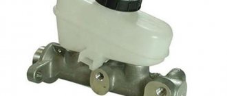
- main and working cylinders;
- tank with “working” fluid;
- connecting pipelines.
Diagram of the hydraulic clutch drive: 1 - flywheel; 2 — clutch driven disc; 3 — clutch basket; 4 — clutch release bearing with clutch; 5 — hydraulic clutch reservoir; 6 - hose; 7 — master cylinder of the hydraulic clutch release; 8 — servo spring of the clutch pedal; 9 — clutch pedal return spring; 10 — clutch pedal travel limit screw; 11 — clutch pedal; 12 — hydraulic clutch release pipeline; 13 — ball joint fork; 14 — clutch release fork; 15 — release spring for clutch release fork; 16 — hose; 17 — working cylinder of the hydraulic clutch release; 18 — clutch bleeding fitting.
The main and working cylinders are made as a piston with a pusher, which in turn are located in the housing. When the driver presses the clutch pedal, the piston of the master cylinder begins to move with the help of a pusher, as a result of which the “working” fluid is cut off from the reservoir. Next, the “working” fluid enters the working cylinder through a connected pipeline.
It is under the influence of the “working” fluid that the pusher and piston move. The pusher, in turn, influences the clutch “fork” and thereby ensures that the clutch is disengaged.
In order to remove air from the drive, special fittings are installed on the working and main cylinders.
Hydraulic clutch operation - video:
Also, some cars use a vacuum or pneumatic drive booster. Its installation makes driving easier.
Clutch release drive device
The stamped clutch pedal 21 is mounted on a welded bracket 12, fixed to the body with bolts 11 and studs 8 with nuts 7. The clutch pedal swings on an axis 16, which is fixedly fixed in the bracket 12. The pedal is secured against rotation by a flat that fits into a shaped hole in one of the cheeks pedal bracket.
The axial movement of the axis is limited by the cotter pin 13 and the shoulder of the flat. Two polyamide bushings 17 rotating on an axis, having collars at one of the ends, are inserted into the pedal hub.
The bushings have high wear resistance and do not require lubrication during operation. A rubber pad 31 is put on the pedal platform. The pedal is held in its original (rearmost) position by the force of the tension spring 15. In this case, the non-adjustable pusher 14, pivotally connected to the pedal with a pin 19, rests against the limiting washer 5, fixed in the axial direction with a locking ring.
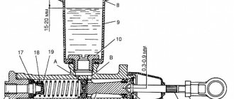
In the initial position of the pedal, the piston 12 of the clutch master cylinder under the action of the spring 8 abuts its end against the washer 14. Between the pusher 14 and the piston 4 there is a constant gap of a = 0.2 - 1.0 mm, which is ensured within the specified limits by the selected dimensions of these parts and the limiting washers 5.
We recommend: Brake caliper: types, principle of operation, malfunctions, repairs
The specified gap provides the piston of the master cylinder with the opportunity to take its original position (with the clutch engaged), guaranteeing communication between cavity a of the cylinder and the filling tank 3 through compensation hole b.
In clutch and foot brake control drives, pedal axles, polyamide bushings, pushers, pedal linings and fasteners are interchangeable. The clutch master cylinder is designed to create pressure in the hydraulic clutch drive system. The cylinder has a cast iron body 9 with an internal diameter of 22 mm with a figured flange; Two pins 18 are screwed into the flange, with the help of which the cylinder and pedal bracket 12 are attached to the front panel of the body. During assembly, up to four (as needed) adjusting shims 6, made of sheet steel 0.5 mm thick each, are installed between the cylinder body flange and the front body shield. These spacers help establish the initial position of the clutch pedal, which should ensure its full travel L until it touches the rubber floor mat, equal to 150-155 mm.
Rice. Clutch release drive: 1 — bracket for fastening the connecting tube; 2 — connecting tube; 3 — clutch master cylinder assembly; 4 — piston of the clutch master cylinder; 5 — limit washer; 6 — adjusting gasket; 7 and 28 - nuts; 8 — master cylinder mounting pin; 9 — supply tank for the clutch master cylinder; 10 — nut holder; 11 — bolt of fastening of the clutch pedal bracket; 12 — clutch pedal bracket: 13 — cotter pin for the clutch pedal axis; 14 — piston pusher of the clutch master cylinder; 15 — clutch pedal release spring; 16 — axis of the clutch and brake pedals; 17 — bushing for the clutch and brake pedal axle; 18 and 33 - washers; 19 and 23 - fingers; 20 and 32 — cotter pins; 21 — clutch pedal; 22 — clutch release fork; 24 — pusher tip; 26 — release spring for clutch release fork; 26 - lock nut; 27 — fork pusher; 29 — clutch operating cylinder; 30 — pin for fastening the working cylinder; 31 — pedal pad; 34 — protective cap; 35 — retaining ring; 36 — piston of the working cylinder; 37 — sealing collar; 38 — spacer mushroom; 39 — spring; 40 — air release valve; 41 — valve protective cap; 42 — tube fastening bracket; 43 — gasket
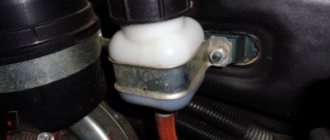
At the top of the master cylinder body there is a tank 3 made of translucent plastic. The reservoir contains a certain supply of brake fluid necessary for the normal operation of the hydraulic clutch drive. The tank is closed with a plastic threaded cap 1, in which there is a hole to communicate the internal cavity of the tank with the atmosphere, and a reflective plate is attached to prevent the brake fluid from splashing out through the specified hole. The flange of the strainer 2 rests on the end of the supply tank, which simultaneously functions as a damper for the brake fluid in the tank.
The nutrient tank 3 is attached to the main cylinder body 9 with a threaded fitting 4, which has a slot at the end for a screwdriver. The sealing gasket 5 after tightening the fitting guarantees the tightness of the connection between the tank and the cylinder body. Through the hole in fitting 4, brake fluid from reservoir 3 flows by gravity into housing 9 of the master cylinder.
A rubber sealing collar 13 is placed on the piston 12 located inside the cylinder, which prevents liquid from leaking out of the cylinder. The piston is cast from zinc alloy. There are six through holes in the piston head, covered with a thin steel ring-valve 11 and an internal working rubber cuff 10. On the outer surface of the cuff there is one annular and six longitudinal grooves. Spring 8 presses the cuff against piston 12, and the piston against thrust washer 14. The other end of the spring rests against threaded fitting 7, which closes the internal cavity of the cylinder body.
A rubber protective cap 16 protects the internal cavity of the cylinder from dust. The cap is tightly placed on the groove in the cylinder body and the pusher rod 17.
The clutch slave cylinder 29 is secured with two studs 30 and nuts 28 on the left side of the clutch housing. The internal diameter of the working cylinder is 22 mm.
The main and working cylinders are connected to each other by a bent copper (6×1 mm) or two-layer steel tube 2 with copper-plated inner and outer surfaces (6×0.7 mm). The spiral located in the middle part of the tube compensates for the change in the distance between the ends of the tube, which is inevitable when the position of the power unit, suspended on rubber cushions, changes relative to the body. In addition to being secured at the ends, the tube has two intermediate attachment points: on the left mudguard of the body using bracket 1 and on the engine crankcase using bracket 42. Rubber gaskets 43 are laid between the fastener and the tube. The ends of the tube have a double conical flaring, the shape and dimensions of which shown in the figure. Before flaring the ends, connecting nuts are put on the tube, with which it is then connected to the main and working cylinders.
Rice. Clutch master cylinder: 1 — reservoir cap; 2 - mesh filter; 3 - tank; 4 — tank fitting; 5 — tank fitting gasket; 6 — master cylinder fitting gasket; 7 — main cylinder fitting; 8 - spring; 9 — main cylinder body; 10 — sealing collar of the main cylinder; 11 — piston valve; 12 - piston; 13 - piston seal; 14 - thrust washer; 15 — retaining ring; 16 — protective cap; 17 — piston pusher; 18 — master cylinder mounting pin
The housing 3 of the working cylinder is a casting made of gray cast iron, having on one side an open cylindrical cavity into which a cast aluminum piston 7 with a rubber sealing collar b, a spacer fungus 5 and a spring 4 are inserted. The spring constantly presses the spherical surface of the fungus against the sealing edge of the cuff and through it the edge to the cylinder mirror, which significantly improves the seal of the working cylinder, especially when there is no pressure in the system (the clutch is engaged).
Rice. Flaring the ends of the connecting tube (tube cross-sectional dimensions: steel - 6 X 0.7; copper 6 X 1.0)
Rice. Clutch slave cylinder: 1 — valve protective cap; 2 — air release valve; 3 - cylinder body; 4 - spring; 5 — spacer fungus; 6 - sealing collar; 7 - piston; 6 — protective cover; 7 - retaining ring
The conical valve 2 screwed into the cylinder body 3 serves to remove air from the hydraulic drive system. Rubber cap 1 is placed on the valve head and protects the internal channel of the valve from clogging.
We recommend: Description and principle of operation of the ESC stability control system
A pusher 27 is inserted into the spherical recess of the piston 36, which is adjustable in length. The pusher is adjusted by screwing it in or out of the fork tip 24. The position of the tip is fixed by the lock nut 26. The spring 25 of the clutch release fork 22 constantly presses the pusher to the spherical surface of the piston and, in the absence of pressure in the clutch hydraulic drive system, moves the piston to the extreme forward position. Since the piston 36 in the cylinder 29 can move in the direction corresponding to the clutch disengagement (to the right in the figure) only under the influence of the working fluid pressure, the formation of vacuum is eliminated, and therefore the penetration of air into the cylinder through leaks in the piston. Therefore, there is no need to maintain excess pressure in the connecting tube 2 and in front of the piston 36, which is usually provided by installing a double valve in the master cylinder, as is done in the hydraulic brake drive (see below). All parts of the clutch master cylinder, with the exception of housing 9 and fitting 7, are interchangeable with the corresponding parts of the brake master cylinder. Since the clutch master cylinder does not have a double valve, the body and fitting of this cylinder are different from the body and fitting of the brake master cylinder. To make it easier to distinguish between the clutch and brake master cylinders, their mounting flanges are rotated 60° relative to each other. A protective rubber cover 8 protects the internal cavity of the working cylinder from dirt.
Clutch drive and its types
Clutch device
The drive is designed for remote control of the clutch directly by the driver from the passenger compartment. Pressing the clutch pedal directly affects the pressure plate.
The following types of drive are known:
- mechanical;
- hydraulic;
- electrohydraulic;
- pneumohydraulic.
The first two types are most widespread. Trucks and buses use a pneumatic-hydraulic drive. Electrohydraulic is installed in cars with a robotic gearbox.
Bleeding the clutch
If you briefly familiarize yourself with the clutch bleeding algorithm, it happens as follows:
- Preparing the system for operation.
- Connecting a rubber hose to the fitting.
- Press the clutch and drain the fluid until all air comes out.
To bleed the hydraulic clutch, you will need the following tools:
- Tool for fixing the clutch pedal.
- Canister for draining brake fluid.
- Rubber hose that we will connect to the drain fitting.
- New brake fluid.
- Standard set of tools.
Before bleeding the clutch, it should be adjusted, since it is impossible to effectively bleed the clutch system if the piston pusher does not move freely. In this situation, the air will not escape.
replacing clutch fluid
First, add fluid to the cylinder reservoir. Its level should not be lower than two centimeters from the highest edge. At the same time, you need to try to ensure that garbage, various foreign impurities, and so on do not get into the system.
Remove the rubber cap from the bypass valve in the upper part of the body, and then put on the hose. Brake fluid will pass through it from the system. About two hundred milliliters of brake fluid is poured into the container.
clutch bleeder nipple
Open the bypass valve and press the clutch pedal several times.
Watch for air bubbles, this is when the entire system is being cleaned. In addition, make sure that the brake fluid level does not fall below three centimeters from the edge. After the pedal is lowered as much as possible, the bypass valve must be screwed in completely. The process is performed several times.
Now remove the rubber hose from the fitting and put on the safety cap. Next, add liquid to the tank.
Basic faults
The main malfunction of clutch drives is the failure of one of the system elements due to wear.
In a mechanical clutch drive, the cable that connects the clutch pedal and the shift fork most often fails. Due to wear, the cable can break, twist or stretch, which leads to poor clutch performance.
The main causes of problems with the operation of the hydraulic clutch drive may be the following:
- Lack of tightness of pipeline systems.
- Lack or small amount of working fluid in the system.
- Failure of one of the cylinders due to wear of the cuffs, rod misalignment or damage to the outer casing.
In the case of an electrohydraulic system, problems with the electrics, the mechanism that drives the cylinders, and the drive control system can be added to the above malfunctions of the hydraulic system.
The clutch drive must always be in good condition, so it is necessary to promptly contact specialized service centers, where experienced technicians can carry out high-quality diagnostics and repairs of individual drive elements.
You can also read on this topic:
“Old men” have no place here: who rules in the secondary market?
Ford Focus 2 fuel filter and its replacement
The engine cooling system is also an indispensable thing in a car.
Still dreaming of big wheels?
Mitsubishi Pajero 3rd generation 1999-2006 with monocoque body
Share on social networks
Alex S October 17, 2013
Published in: Useful tips and car devices
Tags: How a car works
Clutch master cylinder operation
The clutch master cylinder works as follows. When you press pedal 21, pusher 14 moves piston 4, compressing spring 8.
As soon as the cuff 10 closes the bypass hole b, pressure is created inside the cylinder in cavity a, and the liquid passes through the hole in the fitting 7 and through the connecting tube 2 into the working cylinder 29, causing the movement of the piston 36, the pusher 27 and connected to it through the tip 24 and pin 23 forks 22 clutch release. The clutch disengages. At the same time, the tension spring 25 of the fork is stretched and the pressure springs 14 are compressed.
We recommend: Symptoms of a faulty coolant temperature sensor
When the clutch pedal is released, the latter returns to its original position by spring 75, and the piston 12 of the master cylinder, under the action of the return spring 8, moves after the pusher 17 until it stops against the washer 14. At the same time, the pressure in the system drops, and the clutch pressure plate changes under the action of the pressure springs , presses the driven disk against the flywheel again. The clutch engages. Moving the pressure plate until it stops against the driven disk causes the heel associated with it to move through the release levers and the thrust bearing resting against it.
Next, the thrust bearing and the associated clutch release fork move under the action of the tension spring 25, which constantly presses the pusher rod 27 against the piston 36 and moves the latter to its extreme forward position. In this case, the piston displaces liquid from the internal cavity of the working cylinder 29. The liquid through tube 2 returns to cavity a of the main cylinder.
When the clutch pedal is abruptly released, the fluid returning from the working cylinder to the main cylinder does not have time to fill the space vacated by piston 12, and a vacuum is created in cavity a.
Under the influence of this vacuum, liquid from cavity e (where it enters through hole c) flows into cavity a through holes d in the piston head, pushing back valve 11 and the edges of cuff 10. Grooves on the surface of cuff 10 facilitate the passage of liquid from cavity d to cavity a. Subsequently, excess fluid, as it enters from the pipeline, is forced out of cavity a through the compensation hole b into tank 3. The flow of fluid from the connecting tube into the clutch master cylinder stops as soon as the piston of the working cylinder, under the action of the pressure springs and the release spring of the clutch release fork, returns to extreme forward position.
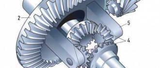
Clutch design and operation
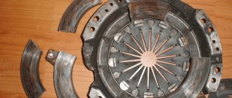
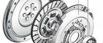
The clutch is a complex mechanical device installed between the engine and the gearbox, the principle of which is based on the transmission of torque from the flywheel of the crankshaft of the internal combustion engine to the input shaft of the gearbox. In simple words, a clutch is a device that connects or disconnects the transmission of rotation to the gearbox shaft from the engine shaft.
The clutch consists of:
- Flywheel.
- Driven disc (clutch disc).
- Torsion damper.
- Crankshaft.
- Crankshaft bearing.
- Tangential leaf spring.
- Drive disc (clutch basket).
- Release bearing.
- Release bearing fork.
- Guide pipe.
- Clutch slave cylinder.
- Gearbox input shaft.
- Gearbox housing.
- Ball head bolt.
- Damper springs.
- Casing.
- Friction pads (discs) that fit onto the driven disc to soften friction between the flywheel and the basket.
The release or pressure plate rotates constantly with the flywheel. The gearbox input shaft is inserted into a splined coupling, which is located on the driven disk.
There is a single-disc clutch, there is a multi-disc clutch. Multi-disc is installed in automatic boxes.
Nuances of clutch operation
Often, drivers tend to associate unevenness and jerking when driving a car with clutch malfunctions. This logic is wrong in most cases.
For example, when a car shifts gears from first to second, the speed drops sharply. It is not the clutch itself that is at fault here, but the clutch pedal position sensor. It is located behind the clutch pedal itself. Sensor malfunctions can be eliminated through simple repairs, after which the clutch will again operate smoothly and without jerking.
Another situation: when changing gears, the car jerks a little, and when moving away it may stall. What could be the reason? Most often, the clutch delay valve is to blame. This valve provides a certain speed at which the flywheel can engage, regardless of how quickly the clutch pedal is "thrown" in. For novice drivers, this function is necessary, because... The clutch delay valve prevents excessive wear on the clutch disc surface.
Characteristics of ceramic and cermet clutches
Recently, fans of extreme fast driving have discovered ceramic and cermet clutches. Ceramic benefits significantly if it is installed on a powerful unit that likes to start with slippage and burn rubber. The sintered clutch can withstand heavy loads and is the first choice for racers.
The discs are made with the addition of carbon fiber, Kevlar and ceramics. This composition allows for a 10-15% increase in torque transmission without increasing the downforce exerted on the basket. As a rule, such disks last four times longer than regular ones. They produce 3, 4, 6-leaf models that cope well with temperature and mechanical loads. Some drivers complain that gear shifting is too sharp with a ceramic clutch, but there is no definite opinion on this matter among motorists yet.
Hydraulic drive device
With this constructive solution, the force is transmitted in a different way. The hydraulic drive circuit does not require a cable; the implementation of a mechanism with this type of control is a little more complicated and the cable is replaced by a hydraulic line. The force is transmitted through an incompressible fluid passing through the line, and since the hydraulic drive is similar to that used in the brake system, the same fluid is used for operation. The clutch device, controlled by a hydraulic drive, includes the following elements:
- Pedal.
- The main cylinder, consisting of a piston with a pusher, a fluid reservoir and sealing collars.
- The slave cylinder has a similar design.
- The line connecting the cylinders.
- Liquid reservoir.
- Additionally, the cylinders are equipped with valves to remove air from the system.
The principle of operation is quite simple and similar to the mechanical control option, the only difference is in the method of transmitting force. When a motorist presses the foot lever inside the car, the piston of the master cylinder is set in motion, the fluid is compressed and, under pressure, moves through the pipeline into the slave cylinder, pushing the piston, which engages the clutch release fork.
The hydraulic drive can also be equipped with a damping device to dampen vibrations from the interaction of the release bearing with the clutch release parts. Pneumatic or hydraulic boosters are often used for commercial vehicles.
Since a hydraulically driven mechanism is a more advanced and complex device that transmits force over a long distance with high efficiency, its cost is higher, and it is characterized by smooth clutch engagement, which is due to the resistance to fluid movement in the structural elements. Among the advantages of a hydraulic drive is also resistance to wear of parts, but repairs are also more difficult than in the case of a mechanical device.
Mechanical and hydraulic drives are endowed with their own operating features, pros and cons of application, while devices of these types provide comfort in driving a vehicle. In passenger cars, the stiffness of the diaphragm spring of the pressure plate is small, so the driver does not need to exert much effort, but on trucks the unit is larger, and in order to operate the basket, more effort is required from the driver, so amplifiers are introduced into the design.
At the end of the procedure, the clutch pedal should work normally, and there should be no problems with the pistons. This is extremely important, since in some cases swelling of various rubber elements can occur, which is very dangerous because it leads to failure of the entire system.
A few words about the clutch cable drive
Foreign automakers extremely rarely equip their cars with such a clutch drive, preferring more reliable hydraulics that rarely fail. But on vehicles of Russian manufacturers, cable clutch mechanisms are standard. And this despite the fact that they have a lot of real shortcomings, which are well known to owners of domestic cars.
The clutch cable needs constant adjustment during operation, which is due to the natural operating wear of the clutch drive. It quickly becomes covered with rust, breaks off at the most unexpected moments, and so on. It is for this reason that every driver driving a car with a manual transmission is simply obliged to know what to do if the cable that interests us fails.
We will talk further about how to change and adjust the cable mechanism. Now let’s describe it in a few words. The cable is connected to the clutch pedal using screws, its other end is also fixed with a screw, but to a special bushing in the shield. In this case, the cable is screwed to the pedal as tightly and reliably as possible, and to the bushing more freely, due to which the described mechanism rotates on the axis without any serious difficulties. In addition, a stop must be installed under the pedal, which protects the cable from breaking.