Clutch VAZ 2101 Zhiguli
- Repair manuals
- Repair manual for VAZ 2101 (Zhiguli) 1970-1985.
- Clutch
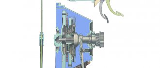
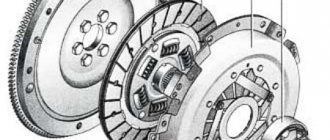
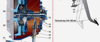
7.1.1 Clutch Clutch assembly 1 – bleeder fitting;
2 – clutch pressure spring; 3 – stepped pressure spring rivet; 4 – pressure disk; 5 – driven disk; 6 – flywheel; 7 – clutch housing; 8 – bolt securing the clutch housing to the flywheel; 9 – gearbox input shaft... 7.1.2 Device features Clutch assembly 1 – bleeder fitting; 2 – clutch pressure spring; 3 – stepped pressure spring rivet; 4 – pressure disk; 5 – driven disk; 6 – flywheel; 7 – clutch housing; 8 – bolt securing the clutch housing to the flywheel; 9 – gearbox input shaft…
7.1.3 Adjusting the clutch release drive The following adjustments are made in the clutch release drive: – set a gap of 0.1–0.5 mm between the pusher and the master cylinder piston (see Fig. Pedal and clutch master cylinder). This gap, necessary for complete disengagement of the clutch, is regulated by a 14-pedal limiter...
7.1.4 Bleeding the clutch hydraulic drive Air in the clutch hydraulic drive is indicated by incomplete disengagement of the clutch, as well as “softness” of the clutch pedal. Removing air from the hydraulic drive PERFORMANCE ORDER 1. Clean the tank and bleeder fitting from dust and dirt. 2. Check the fluid level in the hydraulic drive reservoir, etc...
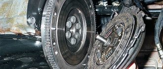
7.1.5 Removing and installing the clutch Centering the clutch driven disk using mandrel A.70081 1 – flywheel; 2 – clutch assembly; 3 – mandrel A.70081 PERFORMANCE ORDER 1. First remove the gearbox (see subsection 7.2.2). Unscrew the bolts and remove the clutch cover assembly by pressing...
7.1.7 Removing and installing the slave and master cylinders of the clutch drive PERFORMANCE ORDER 1. First of all, drain the working fluid. To do this, place one end of the hose on the air release fitting 9 of the working cylinder (see Fig. Working cylinder and clutch release fork), and lower the other end into a clean container, unscrew fitting 9 1/2–3/4 turn and press...
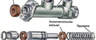
7.1.8 Disassembly, inspection, repair and assembly of the main and working cylinders MAIN CYLINDER Parts of the main cylinder 1 – body; 2 – lock washer; 3 – fitting; 4 – gasket; 5 – cap; 6 – retaining ring; 7 – pusher piston; 8 – sealing ring; 9 – piston of the main cylinder; 10 – spring PERFORMANCE ORDER 1…
7.1.9 Checking the clutch master cylinder on a stand CHECKING THE REAR SEALING RING FOR LEAKS Scheme for checking the condition of the rear sealing ring for leaks 1 – master cylinder; 2 – vessel; 3 – adapter with seal; 4 – pressure gauge; 5 – tee; 6 – adjusting screw; A – air from the compressor; B – I’ll release...
7.1.10 Possible malfunctions of the clutch, their causes and methods of elimination CAUSE SOLUTION METHOD Incomplete release of the clutch (clutch “drives”) Increased gaps in the clutch release drive Adjust the clutch release drive Warp of the driven disk (end runout more than 0.5 mm) Straighten the disk or replace new Unevenness...
↓ Comments ↓
1. Technical data
1.0 Technical data 1.1 Main overall dimensions of the VAZ-2101 car 1.2 Main overall dimensions of the VAZ-21011 car 1.3 Main overall dimensions of the VAZ-2102 car 1.4 Technical characteristics of the cars 1.5 Controls and monitoring devices 1.6 Ignition switch 1.7 Interior ventilation and heating controls
2. Operation and Maintenance
2.0 Operation and maintenance 2.1. Vehicle operation 2.2. Vehicle maintenance
3. Engine
3.0 Engine 3.1 Features of the device 3.2 Possible engine malfunctions, their causes and methods of elimination 3.3 Removing and installing the engine 3.4 Disassembling the engine 3.5 Assembling the engine 3.6 Bench tests of the engine 3.7 Checking the engine on a car 3.8. Cylinder block 3.9. Pistons and connecting rods 3.10. Crankshaft and flywheel 3.11. Cylinder head and valve mechanism 3.12. Camshaft and its drive 3.13. Cooling system 3.14. Lubrication system
4. Fuel system
4.0 Fuel system 4.1. Power system 4.2. Carburetor
5. Ignition system
5.0 Ignition system 5.1 Setting the ignition timing 5.2 Gap between the breaker contacts in the ignition distributor 5.3. Checking ignition devices on a stand 5.4 Possible ignition malfunctions, their causes and methods of elimination
6. Starting and charging system
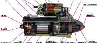
6.0 Starting and charging system 6.1. Battery 6.2. Generator 6.3. Starter
7. Transmission
7.0 Transmission 7.1. Clutch 7.2. Gearbox 7.3. Cardan transmission 7.4. Rear axle
8. Chassis
8.0 Chassis 8.1. Front suspension 8.2. Rear suspension 8.3. Shock absorbers 8.4 Possible malfunctions of the chassis, their causes and methods of elimination
9. Steering
9.0 Steering 9.1 Features of the device 9.2. Inspection, check and adjustment of steering 9.3. Steering mechanism 9.4. Steering rods and ball joints 9.5. Pendulum arm bracket 9.6 Possible steering malfunctions
10. Brake system
10.0 Brake system 10.1. Features of the device 10.2. Checking and adjusting brakes 10.3. Clutch and brake pedal bracket 10.4. Main cylinder 10.5. Front brakes 10.6. Rear brakes 10.7. Rear brake pressure regulator 10.8. Parking brake 10.9 Possible brake malfunctions, their causes and methods of elimination
11. Electrical equipment
11.0 Electrical equipment 11.1. Electrical circuit diagrams 11.2. Lighting and light signaling 11.3. Sound signals 11.4. Windshield wiper 11.5. Heater electric motor 11.6. Control devices
12. Body
12.0 Body 12.1 Features of the device 12.2. Repair of the body frame 12.3. Paint and varnish coatings 12.4. Anti-corrosion protection of the body 12.5. Doors 12.6. Hood, trunk lid, bumpers 12.7. Body glazing and windshield washer 12.8 Instrument panel 12.8. Removal and installation 12.9. Seats 12.10. Heater
13. Features of repair
13.0 Features of repair 13.1. Car VAZ-21011 13.2 Cars VAZ-21013 13.3. Car VAZ-2102 13.4 Cars VAZ-21021 and VAZ-21023
14. Applications
14.0 Appendices 14.1 Tightening torques for threaded connections 14.2 Tools for repair and maintenance of vehicles 14.3 Used fuels, lubricants and operating fluids 14.4 Basic data for adjustments and control
Typical faults
A large number of rubber gaskets and seals are used for various seals in the cylinder. Most often, they are the reason for the unsatisfactory performance of the GVC. The symptoms will be the following:
- the clutch does not disengage;
- the pedal is not pressed;
- brake fluid leaks on the cylinder body;
- The clutch pedal does not return to its original position.
Such signs are characteristic not only of a malfunction of the main circulation system. Only leaks of brake fluid on the body indicate it reliably. You will have to repair or change the clutch master cylinder of the VAZ-2107, the price in the second case will be noticeably higher, but the service life will also be longer.
- it is difficult to change gears;
- the driven disk slips;
- vibration appears;
- The pressure bearing whistles;
- the clutch is hard to disengage;
- The pedal does not return from the lower position.
Destruction of the pressure plate and basket casing can lead to very serious consequences
Almost any malfunction is accompanied by extraneous sounds - noise, knocking, whistling, etc.
What is a hydraulic drive
The clutch in a car is controlled using a pedal. The force from it to the disk can be transmitted in two ways:
- Using a cable.
- Hydraulic drive.
The simplest and most common is the first method, while the “seven” uses the second. Its essence, without going into details, is as follows.
You may be interested in: Tuning the Octavia A7. External finishing. Engine and interior tuning
You will be interested in: Brake pads for Mazda 3: overview of manufacturers, advantages and disadvantages, replacement features, owner reviews
Product location
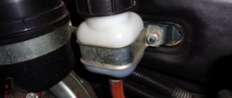
The master cylinder on a VAZ 2107 is located under the hood, directly on the wall separating the interior from the hood, near the driver’s feet. Directly above it is the expansion tank, and next to it are the vacuum booster and the brake master cylinder. Usually, simply looking at the product is enough to determine the problem. The presence of a leak indicates that the part is faulty and requires repair or replacement.
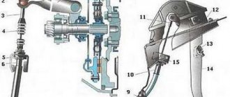
Cars are equipped with clutch master and slave cylinders, without which the operation of the mechanism is impossible. The VAZ 2107 clutch master cylinder is designed to push out brake fluid. Below is a diagram from which you can visually find out the operating features of the unit.
When you press the clutch pedal, the piston moves in the device in question, thereby pushing out the brake fluid. This liquid enters the working cylinder through a tube, where the reverse process is observed (the liquid pushes out the piston). Brake fluid drives a piston, which is connected by a fork to the clutch disc.
https://www.youtube.com/watch?v=pvKxbRTt3QY
Like all parts of any car, the GVC tends to wear out, resulting in the need for repair or replacement. The simplest breakdown of a product is wear of the boot, which can be determined by the characteristic signs of a fluid leak.
To identify a cylinder malfunction, an initial visual inspection is required. It is possible to repair a failed main circulation system on a VAZ 2107; for this you can look for repair kits, but this is not always rational due to the quality of modern spare parts, so it is easier and faster to replace it entirely.
We change it ourselves
Replacing the VAZ 2107 clutch master cylinder begins with the need to pump out the brake fluid from the hydraulic reservoir. This can be done using a syringe or a rubber bulb. Together with this socket or a 10mm wrench, unscrew the bracket securing the expansion tank and move it to the side to gain access to the cylinder.
The next step involves removing the clutch expansion tank hose. To do this, you need to loosen the hose clamp, then disconnect the hose and position it so that it does not interfere with further work. If you want to remove the tank completely, this is done very simply.
Further actions are performed in the following sequence:
- Using a “10” wrench, you need to unscrew the pipeline securing nut to the device. Once the nut is unscrewed, the tube can be moved to the side.
- There is a hose nearby near the steel pipeline, which also needs to be disconnected from the main device. This can be done by loosening the fixing clamp.
- The GCS is fixed to the body using two fastening nuts. To unscrew them, you will need to use a wrench with an extension and a “13” socket. After unscrewing the two nuts, you can remove the product and drain the remaining brake fluid from it. If it is not possible to dismantle the unit, you can press the clutch pedal, as a result of which it will move.
- But repairs are usually not rational, so after removing the old one, a new unit is installed in its place. Installation is carried out in the reverse order of removal. After installation, it is necessary to carry out the process of pumping the hydraulic drive, first pouring fuel fluid into the tank. You can find out how the system is pumped from the relevant material on the website.
After the work is completed, you can test the operating features of the new GVC. If necessary, the RCS (working cylinder) should also be replaced, but you can find out more about this in the corresponding material.
Tips and tricks
When purchasing a new part, owners should remember the quality of the unit, since there are often cases when a cheap product suffers from a short service life. There are many fakes of the VAZ 2104 clutch master cylinder on the market, which are characterized by low quality workmanship and a short service life. The optimal solution is to purchase parts from the manufacturer, which in its production complies with strict standards and GOST norms. At the same time, using the identification number, it is always possible to determine the batch number in the event of a manufacturing defect.
Also, when choosing a new part, owners need to pay special attention to the quality of workmanship. There should be no backlash in some of the moving parts; the parts should maintain optimal mobility. The presence of cracks, stains of unspecified liquid, and burrs on the body is unacceptable. Also, the body, like the rest of the parts, must be numbered with the standard stamp of the manufacturer.
During the repair process, you must always keep a drain container for used brake fluid on hand. Also, before repairs, it is necessary to purchase about a liter of such a substance to make up for losses from opening the system. It is also necessary to remember that reassembling the system after repair must be done in exactly the reverse order.