The basis of any power units and the main component of internal combustion engines is a complex gas distribution mechanism (GDM). The purpose of the gas distribution mechanism is to control the intake and exhaust valves of the engine. On the intake stroke, it opens the intake valve, a mixture consisting of air and fuel or air (for diesel engines) enters the combustion chamber. During the exhaust stroke, the timing belt removes exhaust gases from the combustion chamber by opening the exhaust valve.
Gas distribution mechanism
The gas distribution mechanism consists of the following elements:
- The camshaft - made of cast iron or steel - whose task is to open/close the valves of the gas distribution mechanism when the cylinders operate. It is mounted in the crankcase, which is covered by the timing cover, or in the cylinder head. When the shaft rotates on the cylindrical journals, an impact occurs on the valve. It is acted upon by cams located on the camshaft. Each valve is acted upon by its own cam.
- Pushers are also made of cast iron or steel. Their task is to transfer force from the cams to the valves.
- Inlet and outlet valves. Their task is to supply the fuel-air mixture to the combustion chamber and remove exhaust gases. The valve is a rod with a flat head. The main difference between intake and exhaust valves is the diameter of the head. The inlet is made of chrome-plated steel, and the outlet is made of heat-resistant steel. The valve stem is made in the form of a cylinder with a groove necessary to fix the spring. The valves only move towards the bushings. To prevent oil from entering the combustion chamber of the cylinder, a sealing cap is installed. It is made of oil-resistant rubber. An internal and external spring are attached to each valve; washers and plates are used for fastening.
- Barbells. They are necessary to transmit force from the pushers to the rocker arm.
- Gas distribution mechanism drive. It transmits the rotation of the crankshaft to the camshaft and thereby sets it in motion, and it moves at a speed 2 times less than the speed of the crankshaft. For 2 rotations of the crankshaft, the camshaft makes 1 rotation - this is called the work cycle, during which 1 opening of the valves occurs.
Diagram of the timing device
This is the timing device and the general diagram of the gas distribution mechanism. Now you need to figure out what the operating principle of the gas distribution mechanism is.
What types of timing belts are most widespread on automobile internal combustion engines?
a) spool valves
b) valve
c) both types of mechanisms
Depending on the location of the valve installation, timing belts are divided into mechanisms with lower and upper valves. Which mechanism has fewer parts?
a) with bottom valves
b) with overhead valves
c) have the same number of parts.
How is the timing belt driven?
a) gears
b) chain or toothed belt
c) depending on the type and model of the internal combustion engine, in the manner specified in paragraph a or b.
What is the purpose of the timing belt pusher?
a) to transmit force from the camshaft
b) to transmit force from the piston
c) to rotate the valve around its axis.
Which answer only lists timing parts?
a) camshaft, pusher rod, rocker arm, piston pin, exhaust valve
b) pusher, valve seat, cotters, valve spring retainer, pusher guide
c) valve guide, rocker arm axis, cylinder head, valve spring.
How is the valve spring retainer attached to the valve stem?
a) with a locating pin b) with a thread
c) resistance welding d) crackers.
When an internal combustion engine operates, in some models the valve rotates around its axis to ensure uniform wear on the guide, valve stem, seat and valve disc. How is this achieved?
a) due to a special device b) due to vibration of the valve springs
c) due to the convex shape of the rocker arm. d) due to gas pressure
How to distinguish the intake valve from the exhaust valve of one engine?
a) along the length of the valve stem b) along the diameter of the valve plate c) according to the markings.
Which valve heats up to a higher temperature during internal combustion engine operation?
a) inlet
b) graduation
c) the valves of one cylinder are heated to the same temperature.
What timing parts cause the valves to open and close?
a) opens and closes the camshaft
b) opens the camshaft cam, closes the spring
c) the spring opens and the camshaft cam closes.
The rod transmits force from the pusher to the rocker arm. Can the timing belt design do without rods?
a) they cannot, since such a mechanism will not be able to work
b) maybe in a timing belt with lower valves
c) can be used in a timing belt with overhead valves and a camshaft.
What parts are included in the timing valve assembly?
a) intake valve, valve seat, valve spring, valve guide, compression ring
b) intake valve, valve spring retainer, oil scraper ring, crackers, valve rotation mechanism
c) intake and exhaust valves, valve spring support washer, valve seat, blockers.
The timing belt serves to timely open and close the intake and exhaust valves of the internal combustion engine, ensuring high-quality filling of the cylinder with fresh charge, cleaning it from exhaust gases and sealing the cylinder during compression and stroke. Do the timing belt perform all these functions?
a) the closing and opening of the valves is performed by the KShM
b) the cleaning system fills the cylinders with fresh charge
c) all of the above functions are performed by the timing belt.
What term is used to describe the opening and closing moments of valves relative to dead centers, expressed in degrees of rotation of the crankshaft?
a) valve overlap
b) valve timing
c) the order of operation of the cylinders.
d) ignition timing
15. Which valves are made hollow and the cavity is filled with sodium metal?
a) only intake valves
b) exhaust valves only
c) intake and exhaust valves.
How many bearing journals does an internal combustion engine camshaft have?
a) 2 times smaller than the main journals of the crankshaft
b) 2 times less crankpins of the crankshaft
c) the same number as the crankpins of the crankshaft
d) the same number as the main journals of the crankshaft.
In what sequence is the force transmitted in the valve drive?
a) camshaft, tappet, tappet rod, adjusting screw, rocker arm, valve
b) camshaft, tappet, adjusting screw, tappet rod, rocker arm, valve
c) camshaft, tappet, tappet rod, valve, rocker arm, adjusting screw.
Specify the place to check the thermal gap in the timing belt?
a) between the pusher rod and the adjusting screw
b) between the pusher and the camshaft cam
c) between the toe of the rocker arm and the end of the valve stem.
Operation of the gas distribution mechanism
The operation of the gas distribution system is divided into four phases:
- Fuel injection into the cylinder combustion chamber.
- Compression.
- Working progress.
- Removing gases from the cylinder combustion chamber.
Let's take a closer look at the operating principle of the gas distribution mechanism.
- Fuel is supplied to the combustion chamber of the cylinder due to the movement of the crankshaft, which transmits its force to the piston and it begins to move from the so-called TDC (this is the point above which the piston does not rise) to BDC (this is the point, respectively, below which the piston does not fall) . With this movement of the piston, the intake valve simultaneously opens and the fuel-air mixture fills the combustion chamber of the cylinder. Having injected the required amount of fuel-air mixture, the valve closes. In this case, the crankshaft rotates 180 degrees from its initial position.
- Compression. Having reached BDC, the piston continues its movement. Changing its direction at TDC, at this moment the fuel-air mixture is compressed in the cylinder. When the piston approaches the highest point, the compression phase ends. The crankshaft continues its movement and rotates 360 degrees. And this concludes the compression phase.
- Working progress. The air-fuel mixture is ignited by the spark plugs when the piston is at the highest point of the cylinder. In this case, the maximum compression moment is achieved. Then the piston begins to move to the bottom point of the cylinder, since the gases formed during the combustion of the air-fuel mixture exert enormous pressure on the piston. This movement is the working move. When the piston lowers to BDC, the power stroke phase is considered completed.
- Removing gases from the cylinder combustion chamber. The piston moves to the highest point of the cylinder, all this happens under the force exerted by the crankshaft of the engine timing mechanism. At the same time, the exhaust valve opens and the piston begins to rid the combustion chamber of the cylinder of gases that were formed after the combustion of the fuel-air mixture in the combustion chamber of the cylinder. After reaching the highest point and releasing it from gases. The piston begins its downward movement. When the piston reaches BDC, the working phase of removing gases from the combustion chamber of the cylinder is considered completed, and the crankshaft rotates 720 degrees from its initial position.
For precise operation of the valves of the gas distribution system, synchronization occurs with the operation of the engine crankshaft.
General diagram and interaction of parts
The timely opening of the intake and exhaust valves in the cylinders of an internal combustion engine is ensured by the operation of the gas distribution mechanism or timing mechanism.
This device consists of a camshaft with cams, the required number of rocker arms or valve lifters, springs and the valves themselves. The camshaft gear, belt or chain used to transmit rotation from the crankshaft, and the chain tensioning mechanism are also part of the timing belt.
- Fuel injection phase. The piston begins to move from top dead center to bottom. The fuel supply valve opens, and the fuel-air mixture fills the rarefied space of the cylinder. Having measured the required dose of fuel assembly, the valve closes. The crankshaft has rotated 180 degrees from its original position.
- Compression phase. Having reached bottom dead center, the piston changes direction of movement to TDC, compressing the fuel-air mixture. When the top dead center is reached, the compression phase of the working fluid ends. The crankshaft rotated 360 degrees.
- Work stroke phase. When the piston is at TDC and the maximum design compression ratio is reached, the fuel-air mixture ignites. Under the influence of rapidly expanding gases, the piston moves to the bottom dead center, making a working stroke. When BDC is reached, the third phase of operation of a four-stroke internal combustion engine is considered completed. The crankshaft rotated 540 degrees.
- Exhaust gas removal phase. Under the action of the crankshaft, the piston begins to move towards top dead center, displacing the combustion products of the fuel-air mixture from the volume of the cylinder through the opened exhaust valve. When the piston reaches TDC, the exhaust phase is considered complete, the crankshaft has rotated 720 degrees.
To achieve such precision in the timing of the opening of the intake and exhaust valves, the gas distribution mechanism is synchronized with the engine crankshaft speed. A belt or chain transmits rotation to the camshaft, the cams of which, pressing on the rocker arms, alternately open the intake and exhaust timing valves.
Low valve engines
The gas distribution mechanism of the internal combustion engine has come a long way from the 1900s to the present day.
Lower valve engines with a camshaft in the cylinder block were used everywhere until the mid-twentieth century. The design and design of the intake and exhaust valves, arranged in a row with the plates facing upward, ensured ease of manufacture and low noise engine. The main disadvantage of this design was the complex path of the fuel-air mixture, non-optimal cylinder filling mode, and, as a result, lower power of the power unit.
A gas distribution mechanism of this type was used until the 90s of the twentieth century in trucks. An example of this is the GAZ 52, the production of which ended in 1991.
Mixed valve arrangement
Attempts to increase the power characteristics of internal combustion engines led to the creation of an engine with a mixed valve arrangement. The intake ones were located in the cylinder head, and the exhaust ones were in the block, like a conventional “lower valve”.
There is one camshaft, also located in the cylinder block. The valves responsible for the intake of the fuel-air mixture were controlled by rods - pushers, through which force was transmitted from the camshaft, the exhaust valves - using the usual rocker arm.
This layout scheme ensured a lower fuel assembly temperature, and, as a result, higher power compared to lower valve internal combustion engines.
Overhead valve engines
The gas distribution mechanism, the intake and exhaust valves of which are located in the cylinder head, and the camshaft is in the block itself, was designed by David Buick at the very beginning of the twentieth century. The valves were controlled by push rods that acted on the rocker arms.
This layout scheme is highly reliable due to the transmission of rotation from the crankshaft to the camshaft using a gear. A toothed belt worn out during operation can break, causing serious damage to the timing valve mechanism, while a worn transmission gear will only slightly shift the valve timing, which an experienced driver will notice by changes in engine operation.
The downside is a certain inertia of such a design, which imposes restrictions on engine speed, and, consequently, on torque and the degree of boost. The use of more than two valves per cylinder leads to a more complex gas distribution mechanism and an increase in the overall dimensions of the engine. Four-valve engines of this configuration are used in KamAZ trucks and diesel locomotive engines.
The gas distribution mechanism of the Volga car of the twenty-first model was designed precisely according to the overhead valve design.
- Engines in which the camshaft and timing valves are located in the cylinder head are designated by the abbreviation SOHC. The operating principle and design of the timing valve control mechanism is very diverse. There is a scheme for opening valves using rocker arms, levers and pushers. This engine design became most widespread in the period from the mid-60s to the end of the 80s of the twentieth century. Currently, such engines are installed in inexpensive passenger cars.
- Engines whose gas distribution mechanism includes two camshafts are designated by the abbreviation DOHC. With two valves per cylinder, each camshaft opens its own bank of valves. Such a timing device makes it possible to reduce the inertia of the crankshaft, and thereby significantly increases the speed and power of the internal combustion engine. The operating principle of an engine using four or more valves per cylinder is no different from that described above. Such power units demonstrate greater power than their two-valve counterparts and are installed on most modern cars.
In engines with this type of gas distribution mechanism, the camshaft drive device plays an important role.
The transmission element is a chain located in a hermetically sealed volume and washed with oil, or a toothed belt located on the outside of the engine. A breakdown of the timing drive often leads to dire consequences. A broken belt, worn out during operation, causes an instant stop of the camshaft, as a result of which some valves remain open. The impact of the piston on the protruding plate causes serious damage to the cylinder head. In especially severe cases, repair is impossible and replacement of this engine element is required.
Timing faults
Main malfunctions of the gas distribution mechanism:
- Reducing compression and popping in pipelines. As a rule, it occurs after the appearance of carbon deposits, shells on the surface of the valve, and their burnout, which is caused by a loose fit of the intake and exhaust valves to the seats. Factors such as cylinder head deformation, breakage or wear of springs, jamming of the valve stem in the bushing, and a complete lack of space between the rocker arm and the valves also have an impact.
- Reduced power, engine tripping, and metallic knocks. These symptoms appear because the intake and exhaust valves do not open completely, and part of the air-fuel mixture does not enter the combustion chamber of the cylinder. The consequence of this is a large thermal gap or breakdown of the hydraulic compensator, which causes a malfunction and improper operation of the valves.
- Mechanical wear of parts, such as: crankshaft guide bushings, camshaft gears, as well as camshaft displacement. Mechanical wear of parts, as a rule, occurs when the engine has been operating for a sufficient period of time and the engine is operating within critical limits.
- Engine failure also occurs due to wear of the toothed belt, which has its own warranty period, the chain, which becomes less efficient after a long period of operation and constant exposure to it, the chain guide and the toothed belt tensioner.
In these cases, it is not uncommon to replace the gas distribution mechanism, but it is also possible to repair a damaged part of the gas distribution mechanism.
Camshaft
The cams pressing on the valves are made to move by a special mechanism - the timing drive, or rather another of its components - the gas distribution shaft, which is also called the camshaft. The cams are its integral part, and it is mounted on special support journals in the cylinder head. Depending on the location of the cams on the camshaft, the valves necessary for normal engine operation open one by one, which is the principle of operation of the timing belt. Some engine models, where the cylinders are not in line, have a pair of camshafts.
Operation of the timing shaft system
The camshaft is driven by a crankshaft, at the end of which there is a gear of a specially selected diameter. Another gear is installed on the camshaft. The transmission of torque from the crankshaft to the camshaft is transmitted by a steel chain or a belt with teeth for the gears, which is made of durable reinforced rubber. The operation of the timing mechanism depends on the correct installation of the chain or belt. In this case, all valves open at the right moment, which allows the air-fuel mixture to enter the cylinder, burn there and remove exhaust gases. This is the main principle of operation of the gas distribution mechanism.
Depending on the design, the valve is pressed directly by the cam on the camshaft or through a lever called a rocker, which is acted upon by the cam. The purpose and design of the gas distribution mechanism allows the necessary valves to be opened at the moment the desired engine stroke occurs, which ensures its uninterrupted operation. Any violation leads to malfunction, including breakdown of the power unit.
Timing belt diagnostics
The gas distribution mechanism has 2 inherent problems - loose connection of the valves to the sockets and the inability to fully open the valves.
A loose connection of the valves to the sockets is detected by the following indicators: popping noises that sometimes occur in the intake or exhaust pipes, a decrease in engine power. Factors that cause leaky valve closure may include:
- the appearance of carbon deposits on the surface of valves and seats;
- formation of cavities on working chamfers and curvature of the valve head;
- faulty valve springs.
Incomplete opening of the valves is accompanied by a knocking sound in the engine and a decrease in its power. This breakdown occurs as a result of a significant gap between the valve stem and the toe of the rocker arm. Typical timing failures include wear of camshaft gears, pushers, valve guides, camshaft displacement and wear of bushings and rocker arm axles.
Practice shows that the gas distribution mechanism accounts for approximately a quarter of all engine failures, and preventing these failures and restoring the timing takes 50% of the labor intensity of maintenance and repair work. To diagnose breakdowns, the following parameters are used:
- determine the phases of the gas distribution mechanism of the car;
- measure the thermal gap between the valve and the rocker arm;
- measure the gap between the valve and the seat.
Valve timing measurement
Such diagnostics of the engine timing belt is performed with the engine turned off using a special set of devices, including a pointer, a torque scope, a goniometer and other additional devices. In order to fix the period of opening of the intake valve on the 1st cylinder, it is necessary to rock the rocker arm around its axis, and then direct the engine crankshaft until a gap appears between the valve and the rocker arm. A goniometer for measuring the desired gap is placed directly on the crankshaft pulley.
Measuring the thermal gap between valve and rocker arm
The thermal gap is measured using a set of probes or another special device. This is a set of metal plates 100 mm long, the thickness of which must be no more than 0.5 mm. The engine crankshaft is turned up to the upper limit point, during the compression stroke of the cylinder selected for control. Directly thanks to probes of different thicknesses, alternately inserted into the formed hole, the gap is measured.
This method cannot give results when diagnosing timing belts when the wear of the end of the rod and the rocker arm is uneven, and the labor intensity of this method is very significant. A special device, which consists of a case and a watch-type indicator, allows you to increase the accuracy of measurements. The spring-loaded movable frame contains a personal connection to the leg of this indicator. The frame is fixed between the rocker arm and the valve spring. When the valve opens, during the period of crankshaft rotation, the indicator is set to 0. The thermal gap is recognized by the subsequent reading of the device, taken during the period of crankshaft rotation.
Determining the gap between valve and seat
It can be estimated by the volume of air that will escape through the seal of the closed valves. This procedure goes well with cleaning the injectors. When they have already been removed, remove the rocker arm rollers and cover all the valves. Then compressed air is supplied to the combustion chamber under high pressure. Alternately, a device is placed on any of the controlled valves that allows you to measure air flow. If the air loss exceeds the permitted limit, the gas distribution mechanism is repaired.
What is a gas distribution mechanism (GRM)?
The gas distribution mechanism (GRM) is a mechanism designed to inject fresh charge into the engine cylinders (fuel mixture in classic gasoline engines or air in diesel engines) and release exhaust gases in accordance with the operating cycle, as well as to ensure reliable isolation of the combustion chamber from the environment during time of compression strokes and power stroke.
Depending on the type of devices that inject charge and exhaust exhaust gases, there are two types of gas distribution mechanisms:
The valve train is the most widely used and is used in all four-stroke engines. Upper and lower valve locations are possible. The upper location is currently used more often, since in this case the gas exchange process is more efficient. Typical designs of gas distribution mechanisms with overhead valves are shown in the figure.
Timing belt repair process
It is often necessary to carry out maintenance of the gas distribution mechanism. The main problem is wear of the journals, shaft cams and increased clearances in the bearings. In order to eliminate the gap in the crankshaft bearings, it is repaired by grinding the bearing journals and deepening the oil supply grooves. The necks need to be ground to repair size. After completing the repair work to restore the crankshaft, you need to check the height of the cams.
There should be no even the slightest damage on the supporting surfaces under the crankshaft journals, and the bearing housings must be free of cracks. After cleaning and washing the camshaft, be sure to check the gap between its journals and the hole in the cylinder head support.
To determine the exact clearance, you need to know the diameter of the camshaft journal, this will allow you to install the corresponding bearing. Having installed it on the housing, measure the inner diameter of the bearing, then subtract it from the diameter of the journal and thus find the size of the gap. It cannot exceed 0.2mm.
The chain must not have any mechanical damage and be stretched by more than 4mm. The timing chain can be adjusted: unscrew the locking bolt half a turn, turn the crankshaft 2 turns, then turn the locking bolt all the way.
If you have any questions, leave them in the comments below the article. We or our visitors will be happy to answer them
Thermal clearance of the gas distribution mechanism
As we all already know from life experience, when heated, the overall dimensions of parts increase. And in internal combustion engines, parts experience high temperature loads, which leads to their expansion in size.
In this regard, the designers provided a thermal gap for the gas distribution mechanism, which is designed to ensure that the increasing valve length increases towards the camshaft cam, and does not fall into the cylinder, which will create depressurization. The thermal gap is equal to:
- for VAZ 2108, 2109 cars - 0.2 mm for the intake and 0.35 for the exhaust valves;
- for the “classics” VAZ 2101-207 - the same 0.15 mm;
- for Volga Gas 21 - the same 0.25-0.3 mm;
- for Volga Gas 24 - 0.35-0.4 mm (inlet) and 0.3-0.4 mm (exhaust);
- for Moskvich - 0.15 mm for everyone.
It won't rust behind us!
The gas distribution mechanism (GRM) is a unit that ensures the opening and closing of the engine intake and exhaust valves at a certain point in time. The main task of the timing belt is to timely supply the air-fuel mixture to the combustion chamber and release the exhaust gases.
The gas distribution mechanism includes the following main elements:
- Camshaft. Depending on the design of the timing belt, the camshaft can be installed in the cylinder head or in the engine crankcase (this arrangement is not used on modern engines). This is the main part that is responsible for the sequential opening and closing of the valves. The shaft has support journals and cams, which push the valve stem or rocker arm. The shape of the cam has a strictly defined geometry, since the duration and degree of opening of the valve depends on this. The cams are also multi-directional to ensure alternating operation of the cylinders.
- Timing drive . Torque from the crankshaft is transmitted through the drive to the camshaft. The crankshaft gear is half the size of the camshaft gear. Thus, the crankshaft rotates twice as fast. As a rule, timing drives are divided into two types: chain drive and belt drive, but there is a gear type drive.
- Intake and exhaust valves typically differ in design and size. The intake is made in one piece. It also has a larger plate diameter to ensure better filling of the cylinder. The outlet is often made of heat-resistant steel and has a hollow core for better cooling as it is exposed to higher temperatures during operation. Inside the cavity there is a sodium filler, which melts easily and removes some of the heat from the plate to the rod. The valve plates have special chamfers that provide a tighter fit to the holes in the cylinder head. This place is called the valve seat.
In addition to the valves themselves, the mechanism contains additional elements:
- Springs. Return the valves to their original position after pressing.
- Valve stem seals. Seals that prevent oil from entering the combustion chamber along the valve stem.
- Guide bushing. Installed in the cylinder head housing and ensures precise valve movement.
- Crackers. With their help, the spring is attached to the valve stem.
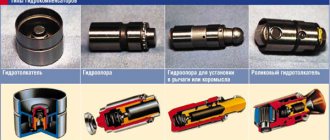
- Pushers . The pushrods transmit force from the camshaft cam to the valve stem. Pushers come in different types (mechanical (cups or washers), roller, hydraulic compensators).
- Rocker arm or levers . A simple rocker is a two-arm lever that performs a rocking motion. Rocker arms may perform differently in different configurations.
- Variable valve timing systems . These systems may have different designs and are not installed on all engines. We will consider the operation of such systems in a separate article.
The main task of the gas distribution mechanism is to open and close the valves in time for a certain period of time. Accordingly, on the intake stroke, the intake valves open, and on the exhaust stroke, the exhaust valves open. Technically, this happens as follows: The crankshaft transmits torque through a drive to the camshaft. A cam on the camshaft pushes a pushrod or rocker arm. The valve moves inside the combustion chamber, allowing access to fresh charge or exhaust gases. After the cam goes through the active phase of action, the valve returns to its place under the action of the spring. During a full working cycle, the camshaft makes 2 revolutions, alternately opening the valves in each cylinder. For example, with a 1-3-4-2 operating scheme, at the same moment in time, the intake valves will be open in the first cylinder, and the exhaust valves in the fourth. In the second and third the valves will be closed.
Types of timing belts
Engines may have different gas distribution mechanism layouts:
According to the location of the camshaft.
There are two types of camshaft position: lower; top. With a lower position, the camshaft is located in the cylinder block next to the crankshaft. This type of arrangement is not used on modern engines. In the upper position, the camshaft is located in the cylinder head (cylinder head) directly above the valves. In this position, various options for influencing the valves can be implemented: through pushers, rocker arms or levers.
By the number of camshafts.
In-line engines may have one or two camshafts. Engines with one camshaft are abbreviated SOHC (Single Overhead Camshaft), and those with two camshafts are abbreviated DOHC (Double Overhead Camshaft). With a two-shaft design, one shaft is responsible for opening the intake valves, and the other for opening the exhaust valves. V-engines use two or four camshafts, one or two for each cylinder bank, respectively.
By the number of valves.
The number and shape of camshafts and the number of cams on them will depend on the number of valves per cylinder. There may be two, three, four or five valves. The simplest option is with two valves: one works for inlet, the other for outlet. In a three-valve engine, two operate for intake and one for exhaust. With four valves: two for intake and two for exhaust. Five valves: three for intake and two for exhaust. The more valves at the intake, the greater the volume of the air-fuel mixture entering the combustion chamber. Increases engine power and dynamics. The most common design is with four valves per cylinder.
By drive type.
There are three types of camshaft drive:
- Geared . The main advantage of such a drive is reliability. However, this type of drive is rarely used.
- Chain . This drive is considered more reliable. But using a chain requires special conditions. To dampen vibrations, dampers are installed, and the chain tension is regulated by tensioners. Depending on the number of shafts, several chains can be used. The chain resource is enough for an average of 150-200 thousand kilometers. The main problem with a chain drive is considered to be the breakdown of tensioners, dampers or rupture of the chain itself. If the tension is poor, the chain can jump between the teeth during operation, which leads to disruption of the valve timing and damage to the valve mechanism.
- Belt . A belt drive does not require lubrication, unlike a chain drive. The belt resource is also limited and on average it is 60-90 thousand kilometers. Toothed belts are used for better grip and reliability. This drive is simpler. A belt breaking while the engine is running will have the same consequences as a chain breaking. The main advantages of a belt drive are ease of operation and replacement, low cost and silent operation.
The operation of the engine, its dynamics and power depend on the correct operation of the entire gas distribution mechanism. The greater the number and volume of cylinders, the more complex the timing device will be.
When writing this article, materials from the TechAvtoPort portal were used.
Classification or types of timing belts
Engines may have different gas distribution mechanism layouts. Consider the following classification.
According to the location of the camshaft
There are two types of camshaft position:
With a lower position, the camshaft is located in the cylinder block next to the crankshaft. The force from the cams is transmitted through pushers to the rocker arms, using special rods. They are long rods and connect the pushrods at the bottom to the rocker arms at the top. The lower location is not considered the most successful, but it also has its advantages. In particular, a more reliable connection between the camshaft and the crankshaft. This type of arrangement is not used on modern engines.
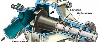
Lower camshaft and timing device
In the upper position, the camshaft is located in the cylinder head (cylinder head) directly above the valves. In this position, various options for influencing the valves can be implemented: through pushers, rocker arms or levers. This design is simpler, more reliable and compact. The overhead camshaft position has become more widespread.
By number of camshafts
In-line engines may have one or two camshafts. Engines with one camshaft are abbreviated SOHC (Single Overhead Camshaft), and those with two camshafts are abbreviated DOHC (Double Overhead Camshaft). One shaft is responsible for opening the intake valves, and the other for opening the exhaust valves. V-engines use four camshafts, two for each cylinder bank.
By number of valves
The shape of the camshaft and the number of cams on it will depend on the number of valves per cylinder. There may be two, three, four or five valves.
The simplest option is with two valves: one works for inlet, the other for outlet. In a three-valve engine, two operate for intake and one for exhaust. With four valves: two for intake and two for exhaust. Five valves: three for intake and two for exhaust. The more valves at the intake, the greater the volume of the air-fuel mixture entering the combustion chamber. Increases engine power and dynamics. The size of the combustion chamber and the shape of the camshaft will not allow making more than five. The most common design is with four valves per cylinder.