VVTi - what is it on Toyota, what is the principle of operation of the valve, valve design, checking the valve
Date: 01/29/2021
VVT-i is considered a system in the gas distribution mechanisms of Toyota cars. It is considered the second generation of mechanisms for changing the valve timing in cars of this brand, which began to be installed on cars in 1996.
Principle of operation
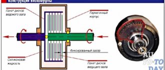
The main element of the system's functioning is the coupling. The mechanism is designed to start work at low speeds, so the valves open, creating good traction.
After increasing the speed, the oil pressure sensor records the increased readings. This causes the VVT-i valve to open. When the valve opens, the camshaft rotates in relation to the pulley.
Cams of a certain shape at the moments when the crankshaft turns, the opening of the intake valves occurs earlier and the closing later. This has a positive effect on the power of the engine.
Engine 1UZ-FE [edit | edit code]
1UZ-FE non VVT-i (1989—1997)
| Toyota 1UZ-FE | |
| Manufacturer | Toyota Motor Corporation |
| Engine code | 1UZ-FE |
| Type | petrol |
| Volume | 3968 cm 3 |
| Maximum power | 261 l. With. , at 5400 rpm |
| Maximum torque | 363 Nm, at 4600 rpm |
| Configuration | V8 |
| Cylinders | 8 |
| Valves | 32 |
| Cylinder diameter | 87.5 mm |
| Piston stroke | 82.5 mm |
| Compression ratio | 10,4 |
| Cooling | liquid |
| Valve mechanism | DOHC |
| Cylinder block material | Aluminium alloy |
| Cylinder head material | Aluminium alloy |
| Clock (number of clock cycles) | 4 |
| Cylinder operating order | 1-8-4-3-6-5-7-2 |
| Recommended fuel | AI-95 |
| Media files on Wikimedia Commons |
Where is the fuel system check valve located?
The basic version of the UZ series engine debuted in August 1989 on the Toyota Crown S130 series, and in October 1989 on the Lexus LS (Toyota Celsior) of the first series (UCF10). It soon appeared on a number of other Toyota and Lexus models.
According to the Toyota labeling system, the engine was designated 1UZ-FE. In the designation, the first digit indicates the generation (1 - first generation), the letters behind the number - the family (UZ), the remaining letters - the version (F - DOHC valve mechanism with “economical” narrow phases, E - electronically controlled fuel injection).
The 90° V-twin engine has a cylinder diameter of 87.5 mm and a piston stroke of 82.5 mm. The intercylinder distance of the cylinder block is 4.15″ (105.41 mm), connecting rod length is 146 mm. The crankshaft has five main plain bearings, the camshafts and pump are driven by a toothed belt. The crankshaft, like the connecting rods, is made of steel. The pistons are made of a special alloy of aluminum and silicon. There are no hydraulic valve clearance compensators; the clearance is adjusted with washers.
The ignition system is contactless, with two coils and two ignition distributors.
In the stock version of the engine, the compression ratio was 10:1, power 245 hp, torque 353 Nm. The engine was coupled only with a four-speed automatic transmission Aisin A-340 series
In August 1994, a slightly modified engine began to roll off the assembly line. The connecting rods were lightened (previous - 628 g, lightweight - 581 g), the compression ratio increased to 10.4. These modifications made it possible to increase power to 261 hp and torque to 363 Nm.
1UZ-FE VVT-i (1997—2002)
| Toyota 1UZ-FE VVT-i | |
| Manufacturer | Toyota Motor Corporation |
| Engine code | 1UZ-FE |
| Type | petrol |
| Volume | 3968 cm 3 |
| Maximum power | 280 l. With. , at 6000 rpm |
| Maximum torque | 407 Nm, at 4000 rpm |
| Configuration | V8 |
| Cylinders | 8 |
| Valves | 32 |
| Cylinder diameter | 87.5 mm |
| Piston stroke | 82.5 mm |
| Compression ratio | 10,5 |
| Cooling | liquid |
| Valve mechanism | DOHC |
| Cylinder block material | Aluminium alloy |
| Cylinder head material | Aluminium alloy |
| Clock (number of clock cycles) | 4 |
| Cylinder operating order | 1-8-4-3-6-5-7-2 |
| Recommended fuel | AI-95 |
| Media files on Wikimedia Commons |
In July 1997, the updated 1UZ-FE began to be produced. The engine received the proprietary Toyota VVT-i (“Variable Valve Timing with intelligence”) variable valve timing system, the compression ratio increased to 10.5. The ignition system has been modernized: Hall sensors have been installed instead of ignition distributors, and individual ignition coils have been used.
These major changes raised power to 280 hp and torque to 407 Nm. After a little adjustment of the control unit, the engine installed on the Lexus GS400 showed 300 hp. and 420 Nm. The engine was coupled with a new “smart” five-speed automatic transmission.
The 1UZ-FE with VVT-i system was one of the ten best engines according to Ward's AutoWorld magazine from 1998 to 2000.
Engine operating modes
When idling, it is important that the system operates reliably even at the lowest speeds. In low speed mode the pressure and speed will be low.
At low pressure, gases will partially flow to the intake manifold, but engine instability is leveled out due to speed.
As a result, the exhaust gases will circulate and partially enter the intake valve, where they burn out in the combustion chamber. This reduces fuel consumption and improves exhaust purity.
At full load the pressure must reach or exceed atmospheric pressure.
When the valves close, exhaust gases will not enter the intake. Accordingly, their kinetic energy will increase as the speed increases.
This improves the efficiency of blowing and compaction. When the engine warms up and is running at low speeds under maximum load, the valve closes as wide an area as possible.
Otherwise, overpurge may occur. As the speed increases, the intake valves need to close later.
In the middle of this process, when the engine reaches 3500-4200 rpm, there comes a point when the purge and compaction time reaches its optimal value. At this moment, the maximum filling of the cylinder occurs.
After reaching the maximum filling point, the last phase begins when the engine runs at full load at high speeds. At this time, the filling rate will begin to decrease and shift the shaft to a later closure.
This increases the press-in period and ensures efficient engine operation while reducing filling rates.
List of car models in which the engine was installed
Toyota bB
Toyota bB (10.2008 - 07.2016) restyling, hatchback, 2nd generation, QNC20
Toyota bB (10.2005 - 09.2008) hatchback, 2nd generation, QNC20
Toyota Passo
Toyota Passo (12.2006 - 01.2010) restyling, hatchback, 1st generation, XC10
Toyota Passo (06.2004 - 11.2006) hatchback, 1st generation, XC10
Daihatsu Boon
Daihatsu Boon (12.2006 - 02.2010) restyling, hatchback, 1st generation, M300
Daihatsu Boon (06.2004 - 11.2006) hatchback, 1st generation, M300
Daihatsu Terios
Europe
Daihatsu Terios (06.2000 - 12.2005) restyling, suv, 1st generation, J102, J122
Japan
Daihatsu Terios (05.2000 - 01.2006) restyling, suv, 1st generation
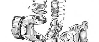
Where is the valve located and methods for checking its performance
The product is placed in the area of the camshaft pulley. The housing is connected to a toothed pulley, and the camshaft to the rotor. Lubricating oil enters the vvti 1nz valve from both sides of the petal rotor. This causes the camshaft to rotate.
As a result, the angle at which the intake valves last opened and closed was determined. This will help distribute it efficiently throughout the mechanism and will not cause valve shock.
When the pressure increases, the locking pin opens.
Why do we need phase shifters at all?
To understand what phase shifters are and why they are needed, first read the useful information below. The thing is that the engine does not work the same at different speeds. For idle and low speeds, “narrow phases” will be ideal, and for high speeds, “wide” phases will be ideal.
Narrow phases - if the crankshaft rotates “slowly” (idling), then the volume and speed of exhaust gas removal are also small. It is here that it is ideal to use “narrow phases”, as well as minimal “overlap” (the time of simultaneous opening of the intake and exhaust valves) - the new mixture is not pushed into the exhaust manifold, through the open exhaust valve, but accordingly, exhaust gases (almost) do not pass into the intake . This is the perfect combination. If you make the “phasing” wider, precisely at low crankshaft rotations, then the “working off” can mix with the incoming new gases, thereby reducing its quality indicators, which will definitely reduce power (the engine will become unstable or even stall).
Wide phases - when the speed increases, the volume and speed of pumped gases increases accordingly
Here it is already important to purge the cylinders faster (from exhaust) and quickly drive the incoming mixture into them; the phases should be “wide”
Of course, the discoveries are driven by the usual camshaft, namely its “cams” (a kind of eccentrics), it has two ends - one is sharp, it rises, the other is simply made in a semicircle. If the end is sharp, then maximum opening occurs, if it is rounded (on the other side), then maximum closing occurs.
BUT standard camshafts DO NOT have phase adjustment, that is, they cannot widen them or make them narrower; nevertheless, engineers set average indicators - something between power and efficiency. If the shafts are tilted to one side, the efficiency or economy of the engine will decrease. “Narrow” phases will not allow the internal combustion engine to develop maximum power, but “wide” ones will not work normally at low speeds.
I wish I could regulate it depending on the speed! This is what was invented - in essence, this is a phase control system, SIMPLY - PHASE Shifters.
Valve structure of the VVTI system of Toyota cars
The product consists of three basic elements: vvt i coupling, solenoid valve and control unit. The system-forming element is considered to be the coupling. It is installed on the engine camshaft pulley.
The valve controls the system. After receiving the signal, the electromagnet begins to move the spool and allow oil to flow through. When the engine is turned off, the spool moves with the help of a spring and is fixed at the desired angle to delay the oil supply as much as possible. When the camshaft is turned at a certain angle, the pressure increases and it is gradually supplied to the rotor.
At this moment, the drainage cavity opens. It is located on the opposite side of the rotor blades. After turning the camshaft to the desired angle, the pulley channels will be blocked and held in this position.
Variable valve timing system
The evolution of variable valve timing systems has allowed engineers to not only shift the valve timing, but also effectively expand and contract them. The next type of variable valve timing systems are solutions based on the use of camshaft cams of different shapes. Thanks to this method, it is possible to achieve a stepwise change in the moment at which the valve opens, as well as change the very height of the valve lift. The list of such systems includes VVTL-i from the auto giant Toyota, VTEC from Japanese Honda and MIVEC from Mitsubishi, a solution from Audi called Valvelift System and others.
These systems are similar to each other both structurally and in operating principle. Only the German Valvelift System is slightly different. The most famous systems are VVTL-i, VTEC and MIVEC. At the heart of such variable valve timing systems are cams with different profiles, as well as a control system. The camshaft in such valve timing control systems is designed so that it has two small cams, as well as one larger cam. The smaller cams are connected to the intake valves using a special rocker arm. The large cam is responsible for moving one unused rocker arm.
This variable valve timing system allows you to switch from small to large cams, depending on the operating mode of the internal combustion engine. The transition between modes is achieved due to the fact that a special locking mechanism is activated. This locking mechanism is based on a hydraulic drive.
When the engine operates at low speeds and under light load, the intake valves are actuated by small camshaft cams, and the valve timing in this mode has a short duration (narrow phase).
If the engine spins up to a certain speed, the control system activates the locking mechanism. As a result, the rocker arms of the small and large cams are connected, which ensures the rigidity of the structure. The connection is made using a special locking pin, and the force on the intake valves begins to come from a single large cam. The small camshaft lobes become inactive at high engine speeds.
Existing varieties of VTEC systems can have three timing control modes at once. In this modification, at low engine speeds, one small camshaft cam operates, which opens only one intake valve. Two small cams are activated at medium loads and engine speeds to open the two intake valves. The large cam comes into action when the power plant reaches a speed close to maximum.
The I-VTEC variable valve timing system, which is presented by the manufacturer Honda, combines the main advantages of both VTC and VTEC solutions. Three-stage regulation provides significant fuel savings. At low engine speeds, half of the intake valves have virtually no activity. Increasing the rotation speed to the mid-speed level activates the deactivated valves, but their lift height does not imply full opening.
Reaching maximum speed forces the intake valves to operate from a large central cam. This cam has a special profile, which is specially selected to achieve maximum valve lift, which means increased efficiency from the internal combustion engine at high power operating modes of the unit. This approach has significantly expanded the possibilities of controlling timing parameters for effectively regulating engine operation in various modes.
If we consider the example with the VVTL-i system from Toyota, then after the engine with this solution reaches a speed of about 6000 rpm, the standard camshaft cam is excluded from operation and is replaced by a cam with a modified profile. The specified cam provides an arc to the valve operation algorithm, shifts (expands) the phase and increases the height of its lift. In practice, this will mean that when the engine reaches high speed mode, the engine will have a sharp increase in thrust, which is necessary to ensure further confident acceleration.
The operation scheme of the VVTL-i system is based on the following algorithm. The opening time and lift height of the intake valves are adjusted similarly to other solutions. When the engine operates at speeds up to 6000 rpm, then the valve is acted upon by a smaller camshaft cam, which presses on the rocker and thus opens the valves. After the speed increases above the set point, a high cam with a special profile begins to control the opening of the valves. To activate it, a special cracker moves under oil pressure.
The control system is responsible for the timely supply of engine oil through a special line at exactly the right moment. Oil pressure and the movement of the crack allow the camshaft cam, through a special rod, which was previously in a free position, to begin to influence the valve through a rocker arm.
Troubleshooting and troubleshooting the system
If the engine is unable to maintain idle speed, the valve filter may not be functioning properly. Most problems in the system are accompanied by engine braking.
Also, problems with the mechanism may occur when the engine is running at low speeds.
Valve cleaning
Many faults can be eliminated by cleaning the vvti sensor. To do this, you need to find the element and dismantle it by removing the plastic cover. Then remove the metal cover that is attached to the generator. Under the cover is the required valve. Next, disconnect the electrical connector and tighten the bolt. After this you can remove the valve.
The VVT system filter can be cleaned using carburetor cleaning fluid. For complete cleaning, remove the plug and clean the mechanism. After complete cleaning, you need to put everything back together and install the alternator belt so that it does not rest against the valve.
Valve repair algorithm:
- Remove the adjusting bar of the car generator;
- We remove the fasteners of the car hood lock, thanks to this you can gain access to the axial bolt of the generator;
- Unscrew the bolt that secures the valve;
- Remove the valve. Just do not pull on the connector under any circumstances, because it fits quite tightly to it and there is a sealing ring on it.
- Remove the Vvti system filter. The presented filter is located under the valve and looks like a plug with a hole for a hexagon.
- If the valve and filter are very dirty, then clean them using a special carburetor cleaning fluid;
- We check the functionality of the valve by briefly applying twelve volts to the contacts. If you are satisfied with how it functions, then you can stop at this stage, if not, then follow these steps.
- We put marks on the valve in order to prevent mistakes during reinstallation;
- Using a small screwdriver, disassemble the valve on both sides;
- We take out the rod;
- We wash and clean the valve;
- If the valve ring is deformed, then replace it with a new one;
- Roll the inside of the valve. This can be done using a cloth, pressing on the rod, to press the new sealing ring;
- Change the oil that is in the coil;
- We replace the ring, which is located on the outside;
- Roll the outside of the valve to press the outer ring;
- The valve repair is complete and all you have to do is reassemble everything in reverse order.
Self-replacement procedure for Vvt-i valve
Often, cleaning and repairing the valve does not give much results and then it becomes necessary to completely replace it. In addition, many car enthusiasts claim that after replacing the valve, the vehicle will perform much better and fuel consumption will drop to approximately ten liters.
Therefore, the question arises: How should the valve be replaced correctly? We will replace the valve step by step.
So, the valve replacement algorithm:
- Remove the vehicle alternator adjusting bar;
- Remove the car hood lock fasteners, thanks to this you can gain access to the axial bolt of the generator;
- Unscrew the bolt that secures the valve;
- We take out the old valve;
- We install a new valve in place of the old one;
- We tighten the bolt securing the valve;
- The valve replacement is complete and all you have to do is reassemble everything in reverse order.
Didn't find the information you are looking for? on our forum.
VVTI Valve Check
It is not always necessary to replace the coupling in case of malfunctions. Checking the vvti valve is simple. To do this, you just need to apply 12V voltage to the sensor contacts. The voltage should not be supplied for a long time, because the valve cannot operate for a long time at low voltage. When voltage is applied, the rod retracts inward, and when you stop applying current, it returns to its original position.
If the stem moves easily, the valve is working properly. It has to be washed and lubricated. After this, it will function stably. If problems are noticeable, then it is worth considering the option of repair or replacement.
Possible causes of valve failure
How to Check the Adsorber Valve on Kalina
There are not so many main reasons for valve malfunctions. There are two that are particularly common. So, the VVTI valve may fail due to breaks in the coil. In this case, the element will not be able to respond correctly to voltage transfers. Diagnosis of the malfunction is easily carried out by checking the resistance measurement of the sensor coil winding.
The second reason why the VVTI (Toyota) valve does not work correctly or does not work at all is jamming in the stem. The cause of such jamming may be simple dirt that has accumulated in the channel over time. It is also possible that the sealing rubber inside the valve is deformed. In this case, restoring the mechanism is very simple - just clean the dirt from there. This can be done by soaking or soaking the element in special liquids.
What is Dual VVT i and VVT iE
Dual VVT-i is considered a popular gas distribution system in cars. Functions the same as on VVT-i, but it is a standard dual VVT-i system where the clutches are attached to the camshaft pulley. The system helps achieve greater fuel efficiency at any speed. Motors for such a system must be more flexible.
VVT-iE is also a variation of gas distribution systems, but its operation uses an electric motor. The operating principle is similar to VVTL-i, but the camshafts can be deflected at certain angles in order to advance or delay the reduction in oil pressure. This happens thanks to an electric motor. The system will not depend on engine speed and temperature conditions. When operating at low speeds, there is not enough pressure to move the clutch. Its operation is considered highly environmentally friendly and helps new generation engines achieve maximum power and operate the vehicle efficiently.
Top
Soft start or Fiat MultiAir, BMW Valvetronic, Nissan VVEL, Toyota Valvematic
If you want smoothness, please, and here the first company in development was (drum roll) – FIAT. Who would have thought, they were the first to create the MultiAir system, it is even more complex, but more accurate.
“Smooth operation” is applied here to the intake valves, and there is no camshaft at all. It is preserved only on the exhaust part, but it also has an effect on the intake (I’m probably confused, but I’ll try to explain).
Principle of operation. As I said, there is one shaft and it controls both the intake and exhaust valves. HOWEVER, if it affects the “exhaust” exhaust mechanically (that is, simply through the cams), then the influence is transmitted to the intake through a special electro-hydraulic system. On the shaft (for intake) there is something like “cams” that press not on the valves themselves, but on the pistons, and they transmit orders through the solenoid valve to the working hydraulic cylinders to open or close. In this way, the desired opening can be achieved within a certain period of time and speed. At low speeds, the phases are narrow, at high speeds they are wide, and the valve moves to the desired height because everything here is controlled by hydraulics or electrical signals.
This allows for smooth activation depending on engine speed. Now many manufacturers also have such developments, such as BMW (Valvetronic), Nissan (VVEL), Toyota (Valvematic). But these systems are not completely ideal, what’s wrong again? Actually, here again there is a timing drive (which takes up about 5% of the power), there is a camshaft and a throttle valve, this again takes a lot of energy, and accordingly steals efficiency, I wish I could give them up.
How to check the phase regulator
There is one simple method for checking whether the phase regulator is working in the engine or not. To do this, you only need two thin wires about one and a half meters long. The essence of the check is as follows:
Remove the plug from the connector of the oil supply valve to the phase regulator and connect the prepared wiring there. The second end of one of the wires must be connected to one of the battery terminals (the polarity in this case is not important). Leave the other end of the second wire hanging for now. Start the engine when cold and leave it idling.
It is important that the oil in the engine is cool! Connect the end of the second wire to the second terminal of the battery. If the engine then begins to “choke”, it means that the phase regulator is working, otherwise it’s not!
The phase regulator solenoid valve must be checked using the following algorithm:
- Having selected the resistance measurement mode on the tester, measure it between the valve terminals. If you rely on the data from the Megan 2 manual, then at an air temperature of +20°C it should be within 6.7...7.7 Ohms.
- If the resistance is lower, it means there is a short circuit; if it is higher, it means a break. In any case, the valves are not repaired, but replaced with new ones.
The resistance can be measured without dismantling, but the mechanical component of the valve must also be checked. For this you will need:
- From a 12 Volt power source (car battery), apply voltage using additional wiring to the electrical connector of the valve.
- If the valve is in good working order and clean, then its piston will move down. If the tension is removed, the rod should return to its original position.
- Next you need to check the gap in the extreme extended positions. It should be no more than 0.8 mm (you can use a metal feeler gauge to check valve clearances). If it is smaller, then the valve must be cleaned according to the algorithm described above. After cleaning, electrical and mechanical checks should be carried out, and then a decision on replacement should be made. repeat.
Phase regulator error
If on Renault Megane 2 the control unit has generated error DF080 (camshaft characteristic change circuit, open circuit), then you must first check the valve using the above algorithm. If it works normally, then it is necessary to “ring” the wire circuit from the valve chip to the electronic control unit.
Most often, problems arise in two places. The first is in the wiring harness that goes from the engine itself to the engine control unit. The second is in the connector itself. If the wiring is intact, then look at the connector. Over time, the pins on them loosen. To tighten them you need to do the following:
- remove the plastic holder from the connector (pull it up);
- after this you will have access to internal contacts;
- similarly, you need to dismantle the rear part of the holder body;
- after that, alternately pull out the first and second signal wires through the back (it’s better to act one at a time so as not to confuse the pinout);
- on the freed terminal, you need to tighten the terminals using some sharp object;
- put everything back in its original position.
Error codes and solenoid valve replacement
If it was noticed that during the process of gaining power by the Peugeot 308 engine, the car begins to twitch, and the on-board computer displays an error message, the phase adjustment valve of the Peugeot 308 may have failed. This can be confirmed by error codes P0013 and P0014 received after diagnosing the engine.
If the phase valve malfunctions, a check engine error will immediately appear on a Peugeot car, followed by the engine switching to emergency operation.
The interpretation of received errors after diagnostics may mean the following:
- The phase solenoid valve is broken, which is why there is no full oil supply to the phase shifter. Because of this, the exhaust camshaft does not rotate to the set angle. In such a situation, it is necessary to replace the failed part.
- The sealing rings that seal the oil lines have been damaged. To eliminate the damage, they need to be replaced.
- The wiring of the exhaust camshaft position control sensor is damaged, causing incorrect data to be sent to the electronic control unit. To repair, you need to check the connection of the terminal contacts on the sensor.
Replacing the timing system solenoid valve of a Peugeot 308 consists of the following simple steps:
- The terminals on the battery are disconnected.
- The connector on the solenoid valve is disconnected.
- The mounting bolt is unscrewed.
- The broken solenoid valve is removed.
- A new spare part is inserted and the mounting bolt is tightened.
- All disconnected wires are connected in their places.
By replacing the solenoid valve on a Peugeot 308, you can restore acceleration dynamics, stabilize engine speed, reduce exhaust gas levels and, of course, remove the error on the on-board computer display.
Checking the performance of the camshaft position sensor without diagnostics
First of all, you need to find out where the phase sensor is located on your car model. You will not be able to find this information in the instruction manual; repair and maintenance literature is required. For example, let's look at the photo of the location of the DPRV in the engine compartment of a VAZ 2112:
The oval connector with three pins is in the center of the illustration.
Checking the phase sensor begins with an external inspection. Before removing the sensor, you need to make sure that the housing, connector are intact, and that there are no signs of burning or technical fluids. Since the device is located under the hood and is not protected from external influences, the cause of the malfunction may be a simple break in one of the wires.
Even if the wiring looks good, it is recommended to check it with a multimeter in the area from the sensor connector to the electronic engine control unit block. After connecting the tester terminals to the connector contacts, ask an assistant to move the cable to look for hidden breaks. After which you need to check the cleanliness of the contacts: they may be oxidized.
Another reason for the malfunction, which does not manifest itself clearly, is the presence of an extraneous pulse signal that affects the transmission of information along the data cable. These could be impulses from the injector control wires or high-voltage spark plug wires. To eliminate the negative impact, it is necessary to bring the wiring of all wires in the engine compartment to the standard layout. No foreign wires should be attached to the DPRV cable, especially from non-standard devices: xenon control unit, parking sensors, additional sound signal. Noise from these devices is difficult to diagnose, but can have a negative impact on the operation of the phase sensor.