Shut-off valves are designed to protect against accidents and tragedies. If there is any suspicion of a leak, the gas valve is first turned off, and then repair work is carried out. However, it is not always possible to sense the increased gas concentration in the room in a timely manner. Solenoid valves (or solenoid valves) were developed for such cases.
In this article we will analyze the design and operating principle of the solenoid valve, consider what types exist, and also study the requirements for installing these devices.
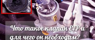
Why do you need a solenoid valve: description and purpose
Unlike a thermal shut-off valve (which shuts off the gas supply at high temperatures, for example, in the event of a fire), the solenoid valve is designed primarily to prevent an accident. While a conventional faucet has to be turned manually, modern shut-off valves are actuated automatically when current is applied to the solenoid coil. In this way, you can not only shut off, but also regulate the fuel supply using automation.
Such valves can be used in water supply, heating or gas pipelines. They are used in households, industrial facilities and automotive systems.
The need to level out water hammer
Indeed, the solenoid valve is very finicky when it comes to water hammer. By the way, they are inevitable if the main medium in the pipe is liquid.
By and large, it doesn’t really matter what kind of liquid we are talking about:
- petrol;
- water;
- alcohol, etc.
As the pressure in the system increases, the occurrence of water hammer becomes inevitable. This means that the valve will not last long. Experts suggest using the following recommendations to reduce negative consequences.
Use a pressure reducing valve before the solenoid valve. It will effectively reduce blood pressure. It is also acceptable to use rubber pipes in front of the solenoid valve.
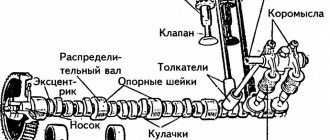
Design and principle of operation
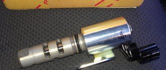
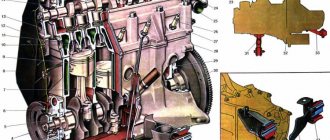
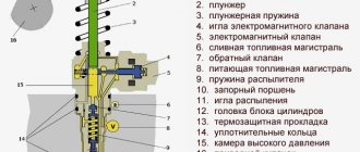
The solenoid valve consists of the following elements:
- body with lid - cast from brass, stainless steel, cast iron or durable polymers;
- shutter - made in the form of a piston, ball or plate;
- coil with core (solenoid) - placed in a sealed housing, and the winding is made of high-strength copper wire, allowing the valve to be opened and closed tens of thousands of times;
- rod, return spring, plunger and diaphragm.
All this allows the use of solenoid valves in various environments (including active ones), allowing them to ensure resistance to external electromagnetic fields, noise and vibration.
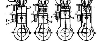
The operating principle of the device is based on electromagnetic induction. As soon as current enters the coil, a magnetic field is created inside it, which affects the core. This force pulls or pulls the core into the body, opening or closing the bolt mechanism.
At home, a combination of a solenoid valve and a gas leak sensor is often used. As soon as the sensor detects an increased concentration of gas in the room, it will apply voltage to the valve, which will shut off the fuel supply to the room.
Types of solenoid valves
Electromagnetic valves are used in various areas of production and everyday life, therefore there are many design solutions based on different parameters.
Based on the position of the shut-off element, valves are divided into:
- normally open (NO) – by default the locking mechanism is open, and when voltage is applied, the fuel supply is shut off;
- normally closed (NC) – by default, the locking mechanism is in the closed state, and when voltage is applied, the fuel supply opens;
- universal or bistable - when voltage is applied, they can be open or closed.
Modern models provide the ability to reconfigure the initial position of the membrane. Therefore, NO devices can be reconfigured to NC state.
Shut-off valves are produced for various environments:
- air;
- water;
- gas;
- pair;
- fuels and lubricants and active media (vacuum valves with increased radiation protection are used).
Valves are also divided based on the characteristics of the external environment:
- normal conditions;
- for wet rooms;
- for high or low temperatures;
- with explosion protection - such devices use special solutions that should not spark when turned on and off.
According to the type of voltage, the coils are divided into:
- high voltage and alternating current - used on highways with large diameter pipes with high pressure;
- low voltage and constant current - used on pipes with low pressure and small diameter.
According to the type of functioning, valves are divided into one-, two-, three- and four-way. Such devices are used to redirect flows from one circuit to another, or are used to mix two flows.
And finally, according to the method of connection to the pipeline, solenoid valves are divided into coupling (threaded) and flanged.
see also
Comments 23
the part of the circuit near the beep is not very good
Gentlemen, tell me what is the reason for the valves being installed directly on the tank, but as soon as you lower the receiver, the air leaves the airbags! And the steering wheel also pulls, could it be because of the valves?
valves have a direction - on one side the pressure should be greater than on the other - i.e. there must be more pressure in the res than in the airbags, otherwise there will be a descent like yours
Pipe valve near the bridge? Put it under the hood so it doesn't freeze
The valve will be on the pipe itself... And the pipe will be on the bottom in the niche under the rear seats next to the receiver...
The main thing is not to forget to warn passengers so that the bricks do not crumble later))))
Connect 1 and 2 and there will be happiness!
One more thing... According to science, the compressor pneumatic switch is screwed into the receiver. It's true. But if there is an ordinary Chinese one, as in the picture, then to save it you can transfer it through the tray to a tube with a pressure gauge and place it in the cabin, and not on the bottom.
I understand... I’ll take it into account... but probably as a further modernization... because it’s too far to chase after fittings... I’ll redo it if necessary...
A HUGE THANK YOU to everyone who responded!
1. It is impossible to damage the coil by incorrect connection. You can ruin the wires... or the battery. Incorrect connection is usually noticeable either by a non-functioning valve or by bright sparks and burning wires. The correct one is the click of the valve. If your hands are not positioned, just carefully poke the wires into the contacts. You will find the ones you need.
2. Polarity does not matter for the coil. Translation: you can swap + and -, the coil will still work.
Do I need to install a relay? ... or you can just do it directly... is a fuse required and how many Amperes?
"""Do I need to install a relay? ...or you can just go straight...""""depending on what buttons they control. If you hold more than 1 ampere, you can directly.
""""is a fuse required and how many amperes?""""" for what? what is the diagram, what are the valves on the fuse, how many are there?
Added introductory notes to the post...
Threat... a local electrician said... that it’s better to put a fuse... on each valve... they say they won’t be superfluous...
In beauty, it’s done like this: You take + After it, you immediately install a 5-10A fuse. You distribute this plus to all your valves.
You take the minus wherever you like and use the buttons to apply it to your valves.
ps. Relay switching signal type? Jerk off is a strange decision. A more powerful toggle switch will be enough. Or a 5-pin INSTEAD of the original signal relay. But not an additional relay if there was none.
PS2. No need to protect every valve
PS3. There are enough buttons for these valves, no relays are needed
Thanks again, I'll take everything into account...
""ps. Relay switching signal type? Jerk off is a strange decision. A more powerful toggle switch will be enough. Or a 5-pin INSTEAD of the original signal relay. But not an additional relay if there was none""
Now there is clarity on the signals... in place of the regular one... I installed Volga signals through the relay... because the regular ones died... now the Volga signals are standing... so as not to pay for the heart attacks of a pedestrian who accidentally drove onto the road... from Typhon... the Volga signals must be left... from the power supply of the Volga signal after the relay through the button , the same one shown in the picture above, we take off the power to the valve... and drive away the trucks occupying the left lane, as necessary... I’m unlikely to be able to organize bells and whistles with the relay...
If the relay is ALREADY installed, then the diagram is absolutely correct. Naturally, there should be a five-pin relay.
I meant that if there was no relay at all or there was a native one in the block, then an additional one is not needed, but it’s easier to get by with a toggle switch.
Plus and minus don't matter. And connect terminals 1 and 2. Take wires with a cross-section of 0.5...0.75.
Will sections of 1-1.5 spoil the porridge?
What the guy said was right about the minimum cross-section. More - ad infinitum.
A valve with an electromagnetic drive is a modern type of shut-off valve. They allow remote control of liquid or gas flows in pipeline systems. Such valves are well integrated into automated process control systems, save scarce human resources and make the operation of enterprises safer. There are a large number of different types of valves for different environments; they differ in their design and purpose.
Installation and operation
Before starting installation work, the pipeline must be empty and the electrical circuit de-energized. Masters also recommend adhering to the following rules:
- the solenoid valve is installed in a horizontal position, with the coil facing up;
- The installation location can be anywhere, the main thing is that there is organized free access to the valve for further maintenance and repair;
- It is recommended to install an additional filter to prevent contamination and damage to parts;
- the direction of movement of the medium must correspond to the direction indicated by the arrow on the device body;
- the solenoid valve should not be subject to load from pipelines (bending, compression, etc.);
- if the valve is installed outdoors, then it should be protected from various natural phenomena - usually a heated casing is enough to protect it from water and low temperatures;
- After installation, the valve must be checked for leaks.
Replacement
- After turning off the power to the equipment, turning off the water supply to the machine and removing the required wall of the device, you need to disconnect the hoses and terminals from the valve.
- Be sure to remember how they were located, and even better, take a photo.
- Next, you need to unscrew the bolts holding the part or remove the latches (in some models they secure the valve).
- By turning the valve, it is removed, after which a new inlet valve is inserted in its place.
- The new part should be secured in the reverse order.
- When the inlet valve is in place, you need to turn on the machine and check whether it has started to take in water.
You can see the process of replacing the water inlet valve on an LG washing machine in the following video.
Possible malfunctions and how to fix them
It is worth noting that high-quality installation and compliance with all operating rules specified by the manufacturer ensure reliable and long-term operation of the device.
But there are cases when the valve fails much earlier:
- Valve depressurization - most likely small mechanical particles have gotten inside the device. We recommend dismantling and disassembling the device, and then installing it together with an additional filter.
- The induction coil can fail if the voltage power is incorrectly supplied, or if the temperature or pressure inside the gas pipeline is exceeded. In addition, moisture may enter the coil, causing a short circuit. In all cases, it is recommended to dismantle the devices and replace the coil.
- Incomplete opening or closing of the valve may be due to contamination of the internal parts, a defective membrane, or voltage remaining on the solenoid.
In any case, repairs to the device can only be carried out by a qualified employee of a specialized organization with permission to work.
IMPORTANT!
The solenoid gas valve does not act as a gas tap, so a gas tap must be installed between the gas line and the valve. If you plan not to use gas for a long time, for example in winter, shut off the gas supply using the gas tap, not the valve.
Solenoid gas valve GV-80
GV-80 is an electromagnetic valve that shuts off the gas supply, designed to ensure the safety of using household gas appliances, and is used in conjunction with a gas leak detector. For example, our experts recommend pairing with the KENAR GD100-CN .
Technical characteristics of the GV-80 valve:
| Permissible working gases | natural gas (methane CH4), household gases (propane C3H8, butane C4H10) |
| Valve opening | manual |
| Closing the valve | electrical impulse, manual |
| Operating voltage of electric pulse | 9 – 12 V |
| Current consumption when triggered | < 1.5 A (pulse) |
| Valve shut-off time | < 1 sec |
| Operating gas pressure | < 10 kPa |
| Housing material | Aluminium alloy |
| Gas-tight material | NBR rubber |
| Operating temperature range | -10°С — +50°С |
| Execution | waterproof |
| Maximum permissible cable length connecting the valve to the gas detector | 20 m |
| Thread size for connection to gas supply pipes | 1/2″, 3/4″, 1″ |