Application – friction transmission
The use of friction gears is currently limited to medium and low power, since at high torques the pressing forces increase accordingly and the gears acquire significant dimensions.
The use of friction gears for high power leads to a corresponding increase in the forces on the shafts and supports and an increase in the dimensions of the gear. Friction gears cannot be used in those mechanisms where the accumulation of errors in the angles of rotation of the links is unacceptable, which is associated with the presence of slipping in these gears.
The use of friction gears for high power leads to a corresponding increase in loads on the shafts and supports and an increase in the dimensions of the gear.
It is legal to use double friction gears that are completely balanced. If large reductions are required, friction wave transmissions can be used, but they operate with a significant loss of speed.
In ordinary cases of using planetary friction gears, when a significant expansion of the range of regulation of the friction gear and a reduction in speed are required, schemes are used in which the gear ratio is expressed by the difference of two terms (Table 138), and not by the sum. In this case, it is advisable to choose schemes in which the driven shaft is connected to the slowest element of the planetary gear - to the carrier.
In ordinary cases of using planetary friction gears, when a significant expansion of the range of regulation of the friction gear and a reduction in speed are required, schemes are used in which the gear ratio is expressed by the difference of two terms (Table 7), and not by the sum. In this case, it is advisable to choose schemes in which the driven shaft is connected to the slowest element of the planetary gear - to the carrier.
| Friction gear schemes for constant gear ratios. |
The latter is decisive for the use of friction gears, since meshing gears do not allow for stepless regulation.
The second method of regulating the speed of the screw is the use of a mechanical friction transmission from an electric motor with a constant speed. The speed control of the screw of larger syringe presses is carried out using a speed variator with V-belts and a gear transmission. Such variators are suitable for transmitting power up to 110 kW, but when using these gears, difficulties arise when operating at low speeds due to the large amount of transmitted torque. Typically, a safety shear pin or friction clutch is used to protect press components from overload.
The simplest way to transfer work between rotating shafts is to use a friction transmission. Friction transmission is usually carried out using two smooth wheels, pressed against one another with a certain force. Due to the presence of this force, when the drive wheel rotates, a friction force arises at the point of contact between the wheels, through which rotation is transmitted to the driven wheel. Such a transmission is called friction, and the wheels are called friction wheels.
The large value of force Q is the main factor limiting the use of friction transmission with cylindrical rollers. This is clearly seen from the example below.
The large value of force Q is the main factor limiting the use of friction transmission with cylindrical rollers. This is clearly seen from the example below.
Large loads on shafts and supports and the inevitability of slipping between rolling elements limit the use of friction gears, despite their significant advantages - simplicity, noiselessness and the ability to use for stepless speed control.
| Diagram of a cylindrical friction transmission.| Schemes of friction gears with a constant gear ratio. a – with cylindrical rollers. I - transmission by rollers with a wedge rim. a – with conical rollers. |
Large loads on shafts and supports and the inevitability of slipping between rolling elements limit the use of friction gears, despite their significant advantages - simplicity, noiselessness and the ability to use for stepless speed control. Friction transmissions with a constant gear ratio are used mainly in kinematic chains of devices.
Materials used in construction
Traditional coupling manufacturing technologies are based on the use of steel alloys with anti-corrosion coatings. Nowadays, the segment of composite carbon materials, Kevlar elements, and so on is also developing. The most technically advanced parts are made from specialized friction materials. In particular, these include retinax, tribonite and press composite. The first is an alloy of barite, asbestos and phenol-formaldehyde resins, supplemented with brass shavings. Tribonite also contains components of petroleum products and composites, thanks to which the friction clutch disc can be used in an aquatic environment. Pressed composites are distinguished by the fact that their structure contains high-strength fibers that increase the wear resistance of parts.
Automatic transmission repair
You won't be able to quickly repair an automatic transmission with your own hands. Theoretical knowledge provides the basis, but in practice many questions always arise. Be prepared to spend more than one day repairing your box. Dismantling alone will take a beginner about 4 hours.
Automatic transmission dismantling
The automatic transmission weighs a lot, has an awkward shape, and, most often, is located in a small space. So, to get to the automatic transmission in a Kia Rio, you need to remove the air filter, battery, engine control unit, and crankcase. In a Land Rover, the exhaust pipe, engine and automatic transmission mounts, cardan shafts, and transfer case will be in the way.
Before dismantling, drain the liquid through the drain plug. Look at what vehicle systems the automatic transmission is connected to. Disconnect the radiator pipes, electrical connectors, and control rods. Be careful not to damage the fasteners or break the wires. Do not use a sledgehammer or chisel for repairs.
Get to the junction between the engine and the torque converter. To access the “donut”, for example, on an Audi A4, you need to remove the wheels, drives, and driveshaft. The subframe that holds the automatic transmission and engine can also interfere. In this case, proceed in stages: prop up the box, unscrew the cushions from the subframe, and the subframe from the body. The torque converter and flywheel mount can be hidden in the flywheel housing hatch or the starter niche in the automatic transmission housing.
Unscrew the automatic transmission and internal combustion engine mounting bolts, do not forget about the selector cable. Remove the box.
Do-it-yourself valve body repair
Self-repair of the hydraulic unit involves flushing the channels and replacing consumables. More complex procedures:
- checking the pressure in the channels;
- drilling holes for plungers;
- restoration of the slab
There is no point in doing it without professional equipment. Even specialists in difficult cases will not be able to guarantee that the valve body will come back to life after repair. Most often, such control units are immediately replaced with used ones.
To access the valve body, disassembling the entire automatic transmission is not necessary. It is enough to remove the pan, filter, disconnect the wiring, and turn off the temperature sensors. Although there are exceptions, for example, the TF-80SC, where the valve body is “hidden” in the planetary mechanism.
General repair algorithm after removing the pan and filter:
- Unscrew the valve body bolts.
- Unscrew the solenoid bolts, remove the mounting brackets and remove the solenoid valves.
- Remove the top cover of the stove.
- Inspect the separator plate. If the tracks are “eaten” by dirt, the part needs to be replaced.
- Remove the springs, plungers, and balls.
- Wash all parts, clean the stove from dirty oil and blockages.
- Assess wear. If there are burrs on the plungers, loss of elasticity of the springs, broken channels - replace them.
- Assemble the hydraulic unit according to the diagram so as not to lose a single ball.
- Install new consumables.
- Screw on the solenoids.
- Wipe the seat of the pan with a clean, lint-free cloth to prevent dirt from getting into the automatic transmission.
- Reinstall the valve plate.
- Install a new filter, a washed pan with a new gasket.
- Fill the oil and check the level.
Do-it-yourself hydraulic unit repair
Do-it-yourself automatic transmission torque converter repair
Without repairing the torque converter, dismantling the automatic transmission and replacing consumables will have a short-lived positive effect. After all, the “donut” will contain a worn-out coupling, a worn out oil seal, and a defective bushing. After repairing the automatic transmission, fresh oil will quickly become contaminated, and the pressure will leak even more forcefully. As a result, after such a rebuild, problems will return or new ones will appear.
The torque converter can only be opened using a special machine that will carefully cut the weld seam of the housing. You will also need equipment to repair the locking clutch. The Mercedes automatic transmission “donut” uses a multi-plate clutch, but its removal and installation requires experienced hands. In addition, the assembled assembly must be tested for leaks, runout, and balanced.
Repairs without experience and equipment in a garage can only be carried out by brave souls who do not feel the burden of buying a new torque converter to replace a damaged one. If you like dynamic and playful driving with an automatic transmission, do not skimp on sending the “donut” for service.
Friction disc resource
The disks themselves have a fairly long service life, even now I’m afraid to guess. They rotate not in air, but in oil (ATF fluid), so the resource is truly enormous.
My personal opinion is that this is a minimum of 350 thousand kilometers, and a maximum of 500 thousand; still, nothing lasts forever!
BUT if you don’t change the lubricant on time, or don’t change it at all, but rely on the name - a maintenance-free machine (although this is nonsense). Then they can fail after only a short mileage, and will not even last up to 100,000 km. So oil is really the deciding factor for them. Why? Read on.
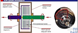
Working principle of the coupling
The main task of a multi-disc clutch is to smoothly connect and disconnect the input (drive) and output (driven) shafts at the right moment using the friction force between the discs. In this case, torque is transmitted from one shaft to another. The discs are compressed due to fluid pressure.
Note that the more the surfaces of the disks are in contact, the greater the magnitude of the transmitted torque. During operation, the clutch may slip, but the driven shaft accelerates smoothly, without jerks or impacts.
The main difference between a multi-disc mechanism and others is that by increasing the number of discs, the number of contacting surfaces increases, as a result of which it becomes possible to transmit more torque.
The basis for the normal operation of a friction clutch is the presence of a regulated gap between the discs. This interval must be equal to the value set by the manufacturer. If the gap between the clutch discs is less than specified, the clutches will be constantly in a “prestressed” state and, accordingly, will wear out faster. If the distance is greater, then slipping of the clutch will be observed during operation. In this case, too, rapid wear cannot be avoided. Precise adjustment of the gaps between the clutches when repairing the clutch is the key to its proper operation.
Application of coupling
Multi-plate friction clutches are widely used in automobiles. This device is used in the following systems:
- clutch (in CVTs without a torque converter);
- automatic transmission (automatic transmission): the clutch in the automatic transmission is used to transmit torque to the planetary gear;
- robotic gearbox: the dual-clutch disc package in the robotic gearbox is used for high-speed gear changes;
- all-wheel drive systems: a friction device is installed in the transfer case (the clutch here is necessary to automatically lock the center differential);
- differential: a mechanical device performs the function of full or partial locking.
Device and main components
A multi-disc friction clutch is structurally a package of steel and friction discs that alternate with each other. Their number directly depends on how much torque needs to be transmitted between the shafts.
Operating principle of a multi-plate clutch
So, there are two types of discs in the clutch - steel and friction. What is their difference? The thing is that the second type of disc has a special coating called “friction”. It is made of materials that have a high coefficient of friction: ceramics, carbon composites, Kevlar threads, etc.
Most often, friction discs are steel discs with a friction layer. However, their basis is not always steel; sometimes these parts of the coupling are made of durable plastic. The discs are attached to the drive shaft hub.
Conventional steel discs without friction coatings are fixed in a drum connected to the driven shaft.
The clutch design also includes a piston and a return spring. Under the influence of fluid pressure, the piston presses on the disk pack, due to which a friction force arises between them, and torque is transmitted. Once the pressure is released, the spring pushes the piston back and the clutch disengages.
There are two types of multi-plate clutch: dry and wet. The second type of device is partially filled with oil. Lubricant is required for:
- more efficient heat removal;
- lubrication of coupling parts.
A wet multi-plate clutch has one drawback - it has a low friction coefficient. Manufacturers compensate for this disadvantage by increasing the pressure on the discs, as well as by using the latest friction materials.
Types of Friction Clutches
Based on the shape of the surfaces subject to friction, these products can be divided into disk (including multi-disk), cone and cylindrical. The first of them are the most popular, as they provide the largest friction surface area.
Depending on the magnitude of the transmitted torque, dry and oil couplings are manufactured. The latter are used to extend the service life of friction material under heavy load conditions. The disadvantage of oil couplings is their complex design.
Also, friction clutches can differ from each other in the type of power cylinders that ensure separation of the plates. Pneumatic and hydraulic designs provide fast operation of the device and are used in systems with high transmitted torque. Electromagnetic friction clutches are more suitable for applications with gradual operation, for example, for presses with a force of up to 100 kN. Also, depending on the type of cylinder, the clutch can have a different type of control: direct, powered by the efforts of a person located behind the working device, or remote, carried out at a distance.
Construction materials
Let's see what the parts consist of:
- Steel. Almost 90% of all useful mass is created from it. This is the most suitable material for its structural characteristics.
- Abrasive coating. Kevlar, carbon compounds of various types, some ceramic coatings. The main selection criterion is the ability to increase friction, it is necessary to transmit force. There is also a different coating in the models, but more often than others, the one indicated in the paragraph is used.
- Oil. Ensures smooth running. During adhesion, the elements put a lot of pressure on their “brothers”; if there is no necessary lubrication, wear increases significantly. But if there is an excessive amount, there is a loss of useful work. It is important to find the perfect balance.
- Plastic. This material is rarely used. As we have already explained, the design of the friction clutch in most cases does not allow this. But sometimes discs are made of plastic.
The operating principle of the electromagnetic clutch
An electromagnetic clutch can have a very different design, but there is also a classic version. Its features are as follows:
- The main elements can be called two rotors, one of which is represented by an iron disk with a thin end protrusion.
- The internal part is equipped with pole pieces that provide radial displacement. To transmit current, a winding is created and connected to the power source through slip rings. Part of this element is located on the shaft.
- The magnetic coupling under consideration has a second rotor, which is represented by a cylindrical shaft with special grooves located parallel to the main axis. They are created so that special bars with pole pieces can be inserted.
The permanent magnet coupling in question has a rather complex design, which ensures accurate and reliable operation. The operating principle of the device is as follows:
- When current appears, an electromagnetic field arises, which intersects with the conductor and begins to interact.
- Such a combination causes the emergence of electromotive force. It may be quite sufficient to move the moving element, taking into account overcoming a certain force.
- In the manufacture of this part, a copper bar is used, which ensures the closure of the circuit. A current passes through them, due to which an electromagnetic force appears.
- The resulting fields provide a driven rotor behind the leading one, while the delay is insignificant.
A similar operating principle is used to create a wide variety of mechanisms. In this case, the device of the machine makes it possible to stop the transmission of torque within a few fractions of a second, which determines its distribution.
Demagnetization of the electromagnetic clutch occurs by disconnecting the power source. In this case, the special properties of the material determine that the magnetic field disappears almost immediately, due to which the reverse movement of the moving element occurs. The used electromagnet windings are designed for a sufficiently large number of coupling and disengagement of the driving element with the driven one.
Only special alloys have magnetic properties that provide the required operating conditions.
The transmission of torque to the clutch can be carried out from an electric motor and other similar elements. The dimensions of all dimensions are in most cases standardized, but it is possible to order the production of the mechanism to order. Classification is usually carried out according to the area of application and many other characteristics.
Species diversity
There are many differences. There are models with different numbers of disk structures and different shapes. Sometimes they even differ in the principle of pressure supply. To figure out which products to choose, you need to understand their main advantages and disadvantages. And also take into account the scope of application. The final choice should also be based on the price aspect. Let's figure it out in order. Let's consider all the options that the modern market provides us.
Disk
The most popular and popular type of friction clutch device. An ideal choice for the machine due to its high friction force. This effect is achieved due to the large drum. There are modifications with “fingers”; one or several ties are used in the structure.
Features can also include:
- Small total volume. Despite the large drum, the product itself is very compact.
- The more plates, the higher the torque transmission.
- The design of the disks is varied. The shape, materials, and coating are different.
Conical
In this version, there is usually a certain number of reels at once. And often their forks have different parameters. The connection between each other is provided by the plate. In this case, the main task in operation becomes the drive. It turns out that this is already a friction clutch.
Cylindrical
These are large devices and should not be used in vehicles. And in production, the process is implemented with great reserve. The equipment is therefore suitable for construction and similar machines.
It is logical to call the main advantages low durability. Axial kink is usually a weak point in this area. But not with the cylindrical modifications, largely due to the size of the drums. And the abrasive in this case is made from materials resistant to frost and high temperatures.
Multi-disc views
Radial dimensions are a sore spot in production. To reduce them, manufacturers use a variety of modifications. And this is a vivid example of such a way out.
Peculiarities:
- The multiplicity of plates allows the radial dimensions to be reduced to acceptable proportions.
- Main specialization: large transport. Including special purposes, construction ones.
- The width of the reels is the main aspect of the branching of model lines on the market.
- The unit can be used both with and without lubricants.
Single drum types
Small products, operation is carried out when it is necessary to transmit small forces. An excellent option for small-sized machines. The main positive factor is saving space. There is one more fundamental advantage. This is reduced heat production. This means that the degree of heating of all links in the chain will be negligible. This is especially important if they are not protected from thermal influences.
Multiple reel types
The purpose of a friction clutch of this profile lies in a different plane. The power transmission becomes greater and the smoothness of the ride is correspondingly better. At the same time, the pressure on all main components is reduced. This means that the service life increases. You have to sacrifice space. After all, the more drums, the larger the sizes. And the price factor is also growing. True, the dependence on the brand itself is even stronger than on the number of parts used.
Bushing
The choice has many logical advantages. Due to the low application of force and pressure, they last longer. And their weight is much lower. And also such models are considered more reliable than many analogues. All this is achieved due to the bushing itself, located between the plates. It absorbs movement, which affects the smoothness and safety of work.
But there are some downsides here. All types and classifications of friction clutches are designed for narrow profiles. After all, models are ideal in their field, but not suitable for others. So bushings are not used for high speeds. After all, due to depreciation, downforce becomes less. And it is simply physically impossible to convey a serious turnover.
Flanged
Small partitions, small drum size. Easy connection to the shaft, minimal number of internal parts, and therefore high reliability. A simple unit that is used in a narrow profile. However, due to installation features, they cannot be installed everywhere.
Articulated
In this option, very wide partitions are more common. And sometimes they are also supplied with rifling. Thanks to the hinges themselves, unnecessary friction within the structure is reduced. This means more efficient work. And the service life also becomes more pleasant. But the minus is also noticeable - narrow specificity. It is used only in drive units, and even then not always.
Cam
If you choose a product for machine coupling, then such a friction clutch is suitable, its design is just suitable for this area. A fixed cone-shaped drum is used. Plates may be missing. Soft fixation allows the drum to practically not feel thorns. This means less wear and tear. The housing itself holds very strong pressure, which is excellent for powerful machines.
Drive options
A typical one has only two disks with a plate between them. A hinge is also often installed to facilitate the operation of the drum. The model range here is the most diverse.
The gradation depends on the following factors:
- Number of revolutions.
- The load applied to the part.
- Total operating time.
Essentially, all design aspects are designed to reduce wear and tear when power is constantly interrupted. After all, the drive can cut off the load at any time.
Bush-finger
A guide piece that is also used as a fuse. Conveniently, it has a wide profile. And it is used not only in production. At the same time, its diversity is much narrower than that of its analogues. This means that the choice is reduced to a minimum. Less hassle, because standard models are usually exactly suitable for the tasks required in production. And the range of such products is now very wide.
Friction
An ideal choice if the forces of the drive shaft are not controlled, they are very large at the beginning of the stroke. And you need to stabilize them without damaging the driven element. Such models are able to absorb the initial impulse to prevent an impact. Start the rotation immediately with slipping, stabilize the rotation over a period, adjust the chain to the same pace.
Clutch
This type of coupling is responsible for smooth coupling of the drive and driven shafts. The complexity of its task is determined not so much by physical coupling as by counteracting environmental loads. To understand the features of such couplings against the background of other parts that provide coupling, we can compare them with their analogues in the form of gear and cam components of the connecting chain. In contrast, friction clutches do not produce strong shocks or overloads when there is a large difference in the speeds of the two shafts. They rather inhibit the activity of the mechanism, thereby ensuring the possibility of coaxial coupling at the most advantageous moment. In other words, they adapt to optimal pairing conditions.
Features of cam-disc clutches
One of the varieties of disc clutches is models with cams on the end surfaces. Such devices consist of three disks. The external drives are connected to the input and output shafts. The connection of the middle disk with the other two is ensured by a protrusion-recess. Cam-disk mechanisms often have a special spring that compensates for the gap between the parts and the idle speed of the main link of the mechanism.
Unlike friction models, in cam devices the middle disk rotates around its center point at the same speed as the input and output shafts.
To avoid the appearance of dynamic loads during operation, the device is turned on only in a stationary state. In this case, the shafts usually rotate at a relative speed of no more than 1 m/s.
Compared to friction models, cam devices are smaller in size, and in these mechanisms there is no relative rotation of the shafts. The number of cams is selected based on the torque to be transmitted.
How does a clutch work?
Let's look at the operating principle of a roller-type clutch, because this type of mechanism is more common in the automotive industry.
A roller clutch consists of two coupling halves: the first half of the coupling is rigidly fixed to the drive shaft, the other half is connected to the driven shaft. When the engine shaft rotates clockwise, the clutch rollers move into the narrow part of the gap between the two coupling halves under the influence of frictional forces and springs. Subsequently, jamming occurs and torque is transferred from the driving half of the coupling to the driven half.
When the drive half of the clutch is turned counterclockwise, the rollers move toward the wide part of the gap between the two halves of the clutch. The drive shaft and driven shaft are separated and no more torque is transmitted.
According to the principle of operation, we note that a roller-type clutch transmits torque in only one direction. When turning in the opposite direction, the clutch simply rotates.
Advantages and disadvantages
Advantages of multi-plate friction clutch:
- compactness;
- When using a multi-disc clutch, the dimensions of the unit are significantly reduced;
- transmission of significant torque with small dimensions of the mechanism (due to an increase in the number of disks);
- smooth operation;
- the ability to connect the drive shaft and driven shaft coaxially.
However, this mechanism is not without drawbacks. For example, steel and friction discs may burn during operation. In wet multi-plate clutches, the coefficient of friction also changes as the viscosity of the lubricant changes.
Friction clutch (Friction shaft) of the main drive of the radial drilling machine 2M55
The friction clutch of the main drive of the 2m55 radial drilling machine is located in the drilling head and smoothly switches the spindle rotation to forward or reverse.
The clutch is controlled by a hydraulic cylinder.
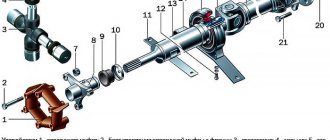
Location of the friction clutch in the drilling head of the 2m55 machine
Drilling head of radial drilling machine 2m55
Location of the friction clutch in the drilling head of the 2m55 machine
In the spindle drive circuit, between the main electric motor and the gearbox, there is a friction clutch, which is designed to smoothly start the drive, reverse the spindle, and also to protect drive elements from overload. The clutch is, in addition, an important link in the system of preselective control of switching speeds and feeds. The friction clutch assembly consists of two clutches - the upper one, which provides forward rotation of the spindle, and the lower one, which rotates the spindle in the opposite direction. Both couplings are assembled on one shaft 25.
Rotation from the engine is transmitted to gear 5 through a gear clutch. Gear 5 is in constant mesh with gear 6 sitting on shaft 25 of the friction clutch. The supports of the gear 5 are located in a separate housing 7. In the same housing there is a boring for the support of the gear 6. This design makes it possible to strictly withstand the technical conditions of engagement of this high-speed transmission. The presence of a gear coupling makes it possible to partially compensate for the inaccuracy of rotation of the motor shaft relative to its seats, which helps reduce the noise of the operating head.
The splines of the shaft 25 are supported by thrust washers 12 and 21 and the drive elements of the coupling 11 and 20, which carry the drive discs. The special design of elements 11 and 20, as well as the drive disks, makes it possible to maintain a guaranteed gap between each pair of disks in the neutral position of the clutch.
Between the driving disks there are driven ones, which have special protrusions that fit into the grooves of the driven cups 13 and 23. The driven disks, like the driving ones, are made of hardened alloy steel and ground. The upper driven cup 13 carries gears 9 and 10, and the lower driven cup 23, which is also a brake drum, is fixedly connected to the reverse rotation gear 24.
A pressure element with cups 14 and 17 moves on shaft 25. When the pressure element moves upward, the drive and driven disks are compressed between cups 12 and 14, as a result of which the driven cup with gears 9 and 10 begins to rotate at the speed of the drive element. When the pressure element moves downward, the disks between cups 17 and 21 are compressed - gear 24 rotates at the speed of the driving element.
The pressure element is driven by a hydraulic cylinder fork through a ball bearing with a spherical cage 16, which serves to compensate for distortions.
Shirts 15 and 19 are installed around the cups 13 and 23, which create an oil bath for more favorable operation of the friction discs.
Cup 23 is covered by a split brake ring 22 with a nylon liner. The braking effect is achieved by spring 34, which tightens the brake ring. The brake release occurs hydraulically when oil enters the brake cylinder cavity. The control of the brake and clutch is interlocked in such a way that in the neutral position of the clutch the cup 23 is braked, and in the working position (the upper or lower clutch is engaged) the cup 23 is released.
Under the friction clutch there is a hydraulic pump 27 of the drilling head, which receives rotation from the shaft 25 through the clutch 26.
Drilling head of radial drilling machine 2m55
Cam devices
Friction clutch with cams is suitable for machine tools. Many models can withstand significant loads, but in this case a lot depends on the drum. For some devices it is fixed between the partitions. It should also be noted that there are models on plates. A conical body is used to hold the parts.
The most common are clutches on squeezing discs. They use drums of small width. The rods in this case are connected to the forks. Many models are used in clutch mechanisms. Tightening pins can be fixed at the base of the partitions. The driven drum is practically not erased. Tying pins are usually used in small sizes.
Friction mechanisms. Types of mechanisms and their structural diagrams
4.9 Actuators
To regulate the flow rate, control valves of the KMR type with nominal diameters from 15 to 50 mm are used. For emergency protection, a control shut-off valve of the KMO type with nominal diameters of 15, 25, 50...
Analysis and synthesis of machine assembly
Types of mechanisms and their structural diagrams
Cam mechanisms
A cam mechanism is a mechanism that includes a cam (Fig. 1 1, 2.12). Cam 1 has a working surface of variable curvature and forms a double-moving pair (DP) with link 2 interacting with it. Fig. eleven…
Types of mechanisms and their structural diagrams
Hydraulic and pneumatic mechanisms
These are mechanisms in which the transformation of motion occurs with the help of solids and liquids or gases...
Types of gears and their main characteristics
Rocker mechanisms
Figure 5 - Rocker mechanism Reciprocating motion in crank mechanisms can be transmitted without a connecting rod. In the slide, which in this case is called the backstage, a cut is made across the movement of the backstage...
Types of gears and their main characteristics
Ratchets
Figure 6 - Ratchet mechanism In addition to continuous rotational motion, intermittent rotational motion is very often used in machines. This movement is carried out using the so-called ratchet mechanism (Figure 6)…
Types of gears and their main characteristics
Cam mechanisms
Cam mechanisms (Figure 7) are used to convert rotational motion (cam) into reciprocating or other specified type of motion...
Catalytic isomerization as a way to improve the quality of gasoline
2.4.1 Mechanisms of catalysis
There are several theories that interpret the mechanisms of catalytic reactions depending on the catalyst used, for example, a bifunctional catalyst consisting of a metal and a support...
Sliding bearings. Friction clutches
Structure and properties of metals and alloys
5.2 Mechanisms of the crystallization process
The appearance of crystals on the basis of large phase fluctuations in liquids is called a spontaneous crystallization process. It consists of two elementary processes. 1…
Rigging
1.1. Lifting mechanisms
All rigging work is carried out using lifting mechanisms and devices: – manual and electrified hoists, – winches, – cargo booms, – cranes. These lifting devices must have: – registration number...
Knots and mechanisms of a weaving loom
Shed-forming mechanisms
Shed-forming mechanisms are varied in design, but they all perform the following functions: – they set the warp threads in motion in the vertical direction...
Knots and mechanisms of a weaving loom
Batt mechanisms
The main technological function of the weaving loom mechanism is to nail the weft thread to the edge of the fabric...
Knots and mechanisms of a weaving loom
Safety mechanisms
On each weaving loom, in addition to the main mechanisms directly involved in the production of fabric, a number of safety devices and mechanisms are installed...
Electric drive based on spur gears
1.2 Electric motors and transmission mechanisms
In mechanical engineering, three-phase asynchronous electric motors with a squirrel-cage rotor of a single series 4A (GOST 19523-81) are usually used to drive machines...
Checking the clutch and signs of malfunction
All clutch malfunctions can be classified into several categories:
- Clutch slippage.
To check the slippage, you need to start driving the car, engage second gear and press the gas pedal all the way, the car should accelerate smoothly, the engine speed should increase linearly, without sudden increases. If you press the gas pedal, but the engine speed only increases, and the car does not accelerate, this means that the friction forces between the flywheel, driven plate and pressure plate are not enough to transmit torque to the transmission input shaft. Quite simply, these parts do not fit together well enough.
- Increased noise.
To check the clutch for increased noise, you need to start the car and, at idle speed, smoothly press the clutch pedal several times. You should not hear any noises that appear when the clutch pedal is operated. It is also recommended to carry out the same check while driving the car smoothly at different speeds. Quite simply, you should not hear any noise that occurs when you operate the clutch pedal. If you still hear any noise, then the clutch is faulty.
- Difficulty changing gears.
To check it is necessary: with the engine idling, press the clutch pedal and engage all gears, including reverse. The same check must be carried out with the car in motion. The gears should be engaged clearly, with almost no effort. There should be no cracking or grinding noise when shifting gears.
- Large free play of the clutch pedal.
We recommend: Cardan transmission and everything you need to know about it.
Try to drive your car, notice how long you have to lift your foot along with the clutch pedal before the car starts to move. The free play should be within 2-3 cm. If it is more, then clutch adjustment is required. Also, this may mean that the clutch driven disc has a lot of wear and may need to be replaced quickly.
Principle of operation
As already noted, couplings can have different tasks, but in general the principle of their operation remains the same - the coupling and separation of two working units. In the process of connecting the friction clutch to the movement of the controlled shaft, the pressing force gradually increases. That is, the friction side carries out translational engagement with the driven shaft. At this moment, it is not so much the coupling itself that is important, but the convergence of the two pressing forces against the background of the work being done on the side of the main shaft.
The safety clutch is designed to safely separate the shafts when the peak torque value exceeds the standard values. The connected shaft will continue to operate stable and smooth in the future. However, this will determine the nature of the movement of the mechanisms served by the friction clutch. The principle of operation of disks when carrying out rectilinear movement suggests that auxiliary components and assemblies through which the transmission is also transmitted will be of great importance as a pairing. For example, these may include final drives, a servo mechanism (when turning), as well as a clutch release fork.
Safety clutch
Couplings of this type are used to safely connect or disconnect shafts when the mechanism operates under high loads. Such elements are capable of automatically restoring the functionality of the unit after the peak overload has ended. But it is important to keep in mind that due to differences in the coefficients of friction of the discs, the tonality of the safety clutch is quite small. Therefore, it is more often used for regular but short-term overloads, when the operation of the mechanism goes beyond the standard torque frequency. Compensation for absorbed energy is provided by a spring, damper elements of the device or heat-removing materials, from which the base of the structure can be made.