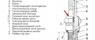
03.24.2021 65 282 KAMAZ
Author: Ivan Baranov
Every motorist who has ever encountered driving a ZIL 130 or 131 car will say with confidence that there are practically no obstacles for this “iron horse”. However, if this is your first time driving such a unit, then you will probably be interested in the ZIL 130 gear shift scheme. Moreover, it is quite original and unusual for the average motorist.
[Hide]
Cabin
The cabin of ZIL-433360 vehicles is all-metal, three-seater, with a whole panoramic non-opening glass wind window of the “Triplex” type.
The cabin doors have sliding glass and rotating window windows. Raising the door windows and securely fixing them in the raised position is carried out by single-lever window lifters.
The cabin doors, left and right, have locks that can be opened from the outside with a key and from the inside with a handle. The lock stopper in the down position prevents the doors from opening from the outside.
To open the rotary window of the door, you need to turn the locking handle by first pressing its button. Electric cab windshield wiper. The driver's seat is equipped with a suspension mechanism with adjustable stiffness depending on the weight; before sitting on the seat, the driver must turn knob 2 to set pointer 3 against the number on the scale corresponding to the driver's weight. The suspension can be locked, while the seat is fixed in a single (height) position.
The adjustment provides several fixed positions of the backrest and seat cushion. The cabin heater is designed to supply warm air into the cabin and heat the windshield glass in case it freezes. The tail of the car is of an integral type, folds to the front.
Salon
1 – parking brake lever; 2 – radiator shutter control handle; 3 – gear shift lever; 4 – direction indicator switch; 5 – windshield washer nozzle; 6 – instrument panel; 7 – windshield washer pedal; 8 – clutch pedal; 9 – foot switch for headlights; 10 – brake pedal; 11 – throttle control pedal.
The steering mechanism of the ZIL-130 was a screw with a special spherical nut plus a piston-rack. The hydraulic booster was built-in. The three-seater cabin is located immediately behind the engine. The seat is adjustable in length, height and backrest tilt. The main options in the cabin included a heater, a windshield wiper with two blades, and a glass washer. For the 60s, the cabin ergonomics are at the highest level. The instrument panel and functional instruments are located very conveniently for the driver. The designers provided two ventilation hatches in the cabin roof. The radiator grille has become a memorable element. The cabin was made of solid metal and had three seats. The engineering staff did a great job, because the car was comfortable and was very different from many Soviet trucks. Drivers received improved conditions for performing their work.
It was much more comfortable to sit inside, because the changes also affected the width - it was increased by 1.2 meters when compared with the ZIL-164 model. Instruments and controls were optimally located in the spacious cabin. In addition, soft seats appeared - for the driver and for passengers (double). The driver's seat could now be adjusted in horizontal and vertical directions. It was also possible to change the angle of the chair back and pillows. It was on the ZIL-130 that the hydraulic power steering wheel debuted. Thanks to this, not only the ease of driving the truck increased, but also its safety - if the front wheel broke, it was easier to keep the truck on the road.
SYNCHRONIZER
How does a manual transmission work?
Synchronizers ensure silent operation when turned on. The difference in the rotation speed of the synchronizer clutch and the engagement of the gear is smoothly equalized due to the friction force that arises between them. The gearbox shift mechanism has a locking device that holds the shift rods in the required position.
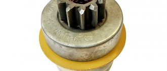
Synchronizer ZIL-130
The synchronizer for LAZ-695, LAZ-697 buses and the ZIL-130 car (Fig. 132) works as follows.
When clutch 11 is moved to the left using the shift fork, the conical bronze ring will move with it and press against the conical surface of gear 1. The conical rings 7 and the clutch ]] are not connected rigidly to each other, but through three locking pins 5 with balls and a spring. Gear 1 and rings 7 rotate at different peripheral speeds. Until these speeds become equal due to the friction force, coupling 11 will shift (Fig. 132, b).
Synchronizer ZIL-130
Both bronze rings 7 are rigidly connected to each other using pins 12. The coupling 11 will move until the conical surface 10 of the coupling rests against the conical surface 9 of the pin (Fig. 132, a and d). When the speeds of the synchronizer rings 7 and the gear cone 1 are equalized, the pin 12 will be located in the center of the hole of the coupling 11, the blocking conical surfaces will separate (Fig. 132, c and d), and the coupling will continue its displacement. Its outer teeth 13 will engage with the inner teeth of the gear shaft 1, which will thus be connected via a synchronizer to the driven shaft 14.
Checking the operation of the gearbox
Transmission
To check the operation of the gearbox, it is recommended to use a special stand (Fig. 7, a). The drive and the device for creating the load are mounted on a welded frame 13 together with a container 11 for oil. Using a hydraulic regulator 9 installed on the cover, the load value is measured. Using eccentric clamps 3, the gearbox that needs to be checked is fixed to bracket 4.
Rice. 7. Specialized stand with a hydraulic loading device for running in and testing gearboxes: a – general view; b – hydraulic load regulator
The drive shaft is connected to electric motor 1 through coupling 2. The gearbox shaft is connected to the pump using a cardan shaft 6, and the pump, in turn, is connected to the oil container by a tube. The hydraulic regulator (pressure gauge) is connected to the discharge pipeline 8. Based on the indicators of the hydraulic regulator 12, the load created by the hydraulic brake is monitored.
A steel sleeve 5 (through hole) is inserted into the technological hole in the regulator housing 1 (Fig. 7, b). The sleeve contains a plug 6 made of hardened steel, which has a channel inside. Oil is supplied from the pump through this channel, having previously passed through adapter 9 at the end of the housing. The tenon, which is located on the other end part, has a handle 3. In order to put the plug in a position that will correspond to a specific gear, a lock is used. The required position of the handle is determined when checking the operation of the gearbox using a graduated disk 2 located below the handle.
A safety valve is installed in one of the seven channels connecting the sleeve and the plug. The function of the valve is to protect the system in cases where the oil pressure exceeds the permissible value. In the remaining channels, which connect the plug space and run perpendicular to the axis, jets 7 and rings 8 are installed. The cross-sections of the jets are selected when setting up the stand.
The channels are closed with plugs 11 with holes through which the oil is drained into the container. In order to check the operation of the gearbox in a certain gear, handle 3 is turned. This creates a resistance equal to the load according to the specifications.
The functionality of each gearbox that has been assembled is checked at the stand without fail. The transmission oil is changed before each inspection.
table 2
Gearbox test mode
| Test conditions | Braking torque on the driven shaft, kGm | Duration, min |
| Tests without load at variable drive shaft speeds from 750 to 3000 rpm in all gears | — | In each gear at maximum speed no more than 2 - 3 minutes |
Load tests at variable drive shaft speeds from 750 to 3000 rpm at:
| 10,0 10,0 10,0 6,0 4,0 10,0 |
During the inspection, defects may be discovered, which then need to be corrected. These include:
- failures when shifting gears;
- spontaneous turning on/off of gears;
- a sound appears when the forks touch the surfaces of the grooves;
- the sounds of impacts that appear are a sign of improper installation of gears;
- small oil leaks where there are connections.
Shifting 2nd, 3rd, 4th and 5th gears is carried out without switching off the electric motor. This checks the operation of the synchronizers. Transitions from low to high gear and vice versa should not produce noise.
Possible gearbox breakdowns
Planetary gearbox working principle
It is possible to determine whether the gearbox is broken or not by the characteristic sounds. Signs of trouble:
- the occurrence of loud noise;
- spontaneous activation of gears;
- oil leak.
If there is strong noise from the transfer case, it is advisable to check the condition of the gears and bearings. These elements must be replaced. When the teeth wear out, the driver may encounter problems such as spontaneous gear shifting.
You need to pay attention to the condition of the sealing elements. With prolonged use of the vehicle, they quickly lose their working properties. This is the reason why fluid will leak
The membrane in the pneumatic chamber and fastenings must be checked
This is the reason why fluid will leak. The membrane in the pneumatic chamber and fastenings must be checked.
Information for legal entities
Design and principle of operation of an automatic transmission
The goods are paid for by bank transfer.
How to get an invoice?
You send us your company details by email, we issue an invoice and draw up an agreement. The contract is signed by both parties and after that the client pays the invoice.
How to pay the bill?
Payment by bank transfer to the company's bank account using the details specified in the invoice. All accounting documents are sent along with the goods. Deferred payment is possible (by agreement with management).
What it includes:
Guaranteed replacement of spare parts in case of defects within 6 months
If a manufacturing defect is detected, you can exchange the part under warranty within six months after purchase.
For this:
- You must send the part back to us.
- If the defect confirms a manufacturing defect, we will send you a new spare part. Our company will cover the shipping costs for sending the replacement part to you.
- If the defect shows that the spare part was damaged as a result of improper use, we can repair it with your consent at your expense. If we refuse to repair, we will send the part back to you. In this case, the transportation costs for sending the part are borne by you.
Repair parts
If a malfunction is detected, you can have the part repaired in our company.
For this:
- Send the part back to us.
- Immediately after receiving the auto parts, we carry out defect detection of the goods (3-10 days).
- After a defect, we can repair the spare part according to our price list with your consent. If we refuse to repair, we will send the part back to you. In this case, the transportation costs for sending the part are borne by you.
Transmission lever
This is the last component in the gearbox assembly (its characteristics from the ZIL-130 are discussed above). The procedure is as follows.
- The selector housing is installed on a special machine or in a vice.
- The locking part is placed in the slot on the crankcase of the unit, a cover is put on the selector, and it is placed in its place.
- The ball surface is treated with a layer of lubricant. A spring is inserted behind the crankcase studs, which is installed together with the ball element support.
- Assemble the intermediate lever of the first and second speeds.
- The handle is secured using a nut, and the gasket is secured to the gearbox cover using sealant.
- Finally, the intermediate part is installed in a special slot on the rod head. The second analogue is placed in the groove of the fork. The lever is secured to the body using special clamps with spring-type washers.
Box ZIL-130 diagram
Moving the driven shaft gear forward engages first gear. 2nd gear is engaged by moving the synchronizer clutch back. If you move the synchronizer clutch forward, 3rd gear will engage. By moving synchronizer clutch 2 back, 4th gear is engaged. If you move the same synchronous clutch forward, 5th gear will engage. The intermediate shaft does not participate in the transmission of torque. Reverse gear is engaged by moving the 1st gear gear until it engages with the reverse gear unit.
A gearbox in which a change in torque is produced by changing the gear ratio. The most widespread are the stepped ones:
Gear shift diagram
gearboxes, where the gear ratio is changed by increasing or decreasing the gear ratio. Mechanisms that change the gear ratio continuously within certain limits are called continuously variable transmissions.
» The following types of continuously variable transmissions are used in cars: hydraulic (hydrodynamic and hydrostatic, otherwise called hydrostatic), mechanical (friction and pulse) and electric.
The most widely used continuously variable transmissions are hydrodynamic torque converters, which are usually installed in combination with stepped or planetary gearboxes. Such transmissions are called hydromechanical.
Step boxes are relatively simple in design and cheaper than continuously variable transmissions, but they have a limited number of gear ratios from three to five.
On off-road and heavy-duty vehicles, the number of gears increases due to the use of an additional gearbox. The higher the gear ratio of the gears in mesh, the greater the torque.
ZIL-130 gearbox diagram
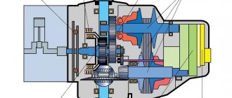
Step-by-step transmissions have forced manual control, while planetary and continuously variable transmissions are mostly semi-automatic and automatic. The five-speed gearbox is shown in Fig. 131. Primary (drive) shaft 1 is connected to the engine crankshaft through the clutch. The secondary (driven) shaft is, as it were, a continuation of the primary shaft and is located on the same axis with it.
Read also: Reinforced bumper on Chevrolet Niva
One end of the secondary shaft is mounted on a roller bearing 10 mounted at the end of the primary shaft, so the secondary shaft can rotate independently of the primary; the second end of the shaft is installed in a ball bearing 8.
Gears are mounted on the intermediate shaft 9. All of them, except for the first gear gear, are made separately and secured to it with keys. To reduce noise during operation and increase durability, the gears that are in constant mesh are helical.
A design feature of the ZIL-130 car gearbox is the presence of constant mesh gears on the secondary shaft. These gears, thanks to special treatment (phosphating) of the mating surfaces of the shaft and the gears of their lubrication grooves, are installed on the shaft without special bushings and bearings.
Checkpoint diagram
In a MAZ-500 type gearbox, the needle bearings of the secondary shaft gears, which are in constant mesh, are lubricated with oil ... under pressure. To do this, a gear oil pump is installed against the front end of the intermediate shaft on the outside of the gearbox housing, driven into rotation from the front end of the intermediate shaft.
shaft The gears are engaged by moving the gear along the splines of the shaft. But in this case, the impact of the teeth is inevitable, since the peripheral speeds of the gears are different. For easy and shock-free gear shifting, it is necessary that the peripheral speeds of the gears being engaged are the same.
The peripheral speed of a gear depends on the number of revolutions of the shaft on which it is mounted and on its diameter: the larger the diameter of the gear and the number of revolutions of the shaft, the greater its peripheral speed. To equalize the peripheral speeds of the gears before engaging them, a special synchronizer mechanism is used, which ensures their silent and shock-free engagement.
How does the gearbox of a car of this brand work?
When the first speed is activated on the gearbox of a car model 130 and 131, the gear wheel begins to move along the grooves and engages with the cardan of the first gearbox mode on the intermediate shaft. In this case, the torque begins to transfer from the primary pulley through gears and other auxiliary elements to the secondary disk. The gear ratio is 7.44.
When the driver engages second speed, the clutch mounted on the synchronizer begins to act on the gear teeth of this transmission. As a result of the fact that this component is already functioning from the components of the intermediate gear, the torque begins to transfer from the primary element to the secondary element. In this case, the moment passes through all the wheels with teeth, as well as the synchronizer cardan. In this case, the gear ratio will be 4.1.
When the driver activates third speed, the synchronizer disc stops affecting the parts and elements of the second gear. The clutch will move along the splines and engage with the third-mode component of the gearbox of models 130 or 131. And this element, in turn, is already engaged with the third-speed wheel of the intermediate cardan. Thus, the torque begins to transfer from the primary pulley through auxiliary elements and the clutch to the secondary pulley. The gear ratio is 2.29.
When the fourth mode is activated, the corresponding synchronizer begins to function. The clutch of this component will move and engage with the gears of the corresponding gearbox mode, which, in turn, is already engaged with the PV wheel. In principle, the process of moving torque is identical to that described above - the torque is supplied to the secondary pulley. Here the gear ratio will be 1.47.
Then, when the driver decides to engage the fifth mode, the synchronizer clutch will engage with the corresponding fourth-speed disc. Further, moving through the movement of the teeth on the PV, the coupling connects both disks into one and it begins to move. In this case, it is carried out on the cardan of model 130 or 131. The gear ratio will be equal to 1.
In general, the process of activating reverse gear is identical to those described above. Only in this case will torque be transmitted from the primary to the secondary through all six gears, and the gear ratio will be 7.09. As you can see, the operating principle of the unit as a whole is not particularly complicated and is quite similar to a traditional mechanical transmission, the difference lies only in certain points.
PTO power take-off.
Its name hints at the fact that it takes part of the engine torque and transfers it to special mechanisms. This could be a hydraulic pump or a utility equipment attachment. The PTO works in close conjunction with the gearbox, and is activated from the vehicle cabin. A huge amount of load and work falls on this small device.
Therefore, they always strive to make it strong and durable. There are 2 types of PTO, clutch dependent and clutch independent. The first one works when the engine is idling. Dependent PTO is lightweight, easy to install and requires almost no maintenance. They are mounted on a manual transmission and activated by the driver from the cab. An independent PTO can work with both manual and automatic transmissions.
It is installed on concrete mixers, road cleaning equipment, and agricultural machines. The place where the PTO is registered can be a gearbox, transfer case, engine, or the space between the engine and gearbox. KOM is a highly durable unit, but even it can break.
Often, breakdowns are immediately visible; the PTO either stops turning on normally or begins to make loud noise. Problems are solved in different ways, starting with simply tightening the nuts and ending with complete disassembly of the PTO. In any case, without the appropriate knowledge and skills, independent repair of the PTO is not recommended by the manufacturer.
WATCH THE VIDEO
Primary shaft
The input shaft is made of steel 25 KhGM, the depth of the nitrocarburized layer is 0.6...0.8 mm, the hardness of the surface layer is HRCe 61...66, the hardness of the core is HRCe 37...46.
Basic data on shaft seats, permissible wear of splines, journals and shaft seats for bearings, as well as data on gears.
Thickness of straight spline teeth - 5, 805…5, 855
The diameter of the roller bearing seat is 43.980…44.007
The diameter of the shaft journal for the ball bearing is 60.003…60.023
Shaft end journal diameter - 24.975...24.995
Secondary shaft
The secondary shaft is made of steel 25 KhGM, nitrocarburization depth 0.8...1.1 mm, surface layer hardness HRCe 61...66, core hardness HRCe 37...46.
The runout of the secondary shaft journals relative to the axis is allowed no more than 0.05 mm. The use of necks on crumbled cemented layers of a fatigue nature is not permitted.
Parameters of the secondary shaft journal splines
The diameter of the journal of the front end of the shaft for the roller bearing is 29.939..29.960
The diameter of the journal for the ball bearing is 50.003…50.020
The diameter of the journal for the bushing of the constant mesh gear of the fourth gear is 47.003...47.020
The diameter of the journal for the second gear constant mesh helical gear is 60.920…60.940
Thickness of the tooth of the splined part of the shaft for the synchronizer:
second and third gears - 8.88...8.94
fourth and fifth gears - 10.90...10.95
The tooth thickness of the splined part of the shaft for the first gear gear is 10.88…10.94
Tooth thickness of the splined part of the shaft for the flange - 5.99...5.94
Intermediate shaft
The intermediate shaft is made of steel 25KhGM, nitrocarburization depth is 0.8...1.1 mm, surface layer hardness HRCe 58...61, core hardness HRCe 35...45.
The runout of the intermediate shaft journals relative to the axis is allowed no more than 0.04 mm. Faulty shaft journals can be repaired by chrome plating and then machined to their nominal dimensions.
The weight of the ZIL-130 box is -98 kg
Dimensions of oil seals: 1 Primary shaft oil seal 42x62x10 2 Secondary shaft oil seal 58x8x16
Box oil ZIL-130 Tad-17 5.1 liters
WATCH THE VIDEO
https://youtube.com/watch?v=VWyLgqqriM4
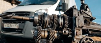
The Likhachev Automobile Plant produced many legendary trucks. These include the 130th model
Let's pay attention to one of the most important mechanisms in the design of a car. The ZIL-130 gearbox is a complex unit that is structurally and functionally different from most other analogues
To properly manage and extend the operating life of a unit, it is necessary to have an understanding of its design and functioning scheme. We will consider these nuances, as well as methods of repair and maintenance below.
ZIL-131 - technical characteristics, photos, modifications review
The legendary truck with a military spring - ZIL-131. The history of the car that brought to life the task of the heads of the USSR, which continues to serve in various fields to this day. The technical characteristics in the tables and the description of the operating qualities make it possible to understand why the machine has such a valuable reputation. The entire ZIL model range.
Car history
In 1959, workers at the Likhachev plant were given a goal to improve the production of the “130” models and the “131” modification. This call for productivity was determined by the twenty-first party congress, or more precisely, by the plan adopted at it for the development of the national economy.
To achieve the goal, decent trucks were needed. However, ZIL-131 was intended for a special purpose - for military purposes. Previously, the Soviet army had at its disposal the ZIL-157, which by the end of the 50s was beginning to become obsolete.
ZIL-157
Despite the fact that prototypes of the ZIS-130 began to be tested back in the mid-50s, the car was planned to be sent to the assembly line only in 1962. Such a long period was partly due to a number of unforeseen situations, which, although not immediately, were successfully dealt with.
Subsequently, on the basis of this model, they began to develop the ZIL-131. Prototypes of the military modification appeared in 1966 and almost immediately successfully passed all tests. And so, in 1967, the Likhachev plant finally began production of the 131st model.
Over a fairly long period of testing, the machine's performance and operational capabilities were significantly improved. This was also facilitated by the constant improvement of the ZIL-130 base chassis.
As a result, the basic characteristics of the car were improved in many ways, the cross-country ability and load-carrying capacity were increased due to the new frame structure and improved engine, the driver’s workplace, together with the cabin, acquired the first signs of ergonomics.
For the 1960s, such innovations for off-road trucks were enthusiastically received. Production did not stop there, and in 1986 the ZIL-131 received a new power unit, which made it possible to raise the bar of capabilities and reduce resource losses when operating the vehicle.
Exterior and cabin
Like most of their models, ZIL made the “131” model with a hooded body layout. The cabin was externally an exact copy of the 130, only mostly all samples were painted khaki.
The design also remains all-metal. Proving to be impractical, the front part was replaced, and again with a ready-made one, only now from the ZIL-165. The bent fenders and intricate grille shape were replaced with simpler but strict elements.
In the 60s of the last century, such a design was akin to revolutionary, not to mention comparing the new model with the “157” model. For almost forty years, the appearance of the military truck changed only in small details. What catches your eye most is the new windshield, which has been made panoramic.
It was not advisable to hide the engine under the cabin, since this negatively affected several factors at once: access to the engine compartment in the field worsened, and if the engine was damaged during combat operations, an increased danger was created.
Considering the focus on army needs, the appearance was similar to its other brother in the class - Ural-375. There was one country, and enterprises were completely subordinated to the state. The main differences were different solutions to technical issues and engineering structures.
The body had typical characteristics, having on board two folding benches and one removable one. The sides cannot be folded down, except for the rear one, but this does not interfere with convenient shipping and loading.
To stretch the awning, you can install special arcs. The structure of the vehicle made it possible to install other modules instead of a cargo body, such as a field kitchen, a first-aid post, a radio station, and Katyusha and S-125 missile launchers; as well as civilians - a boom with a cradle, a fire truck.
It was comfortable to be inside due to several innovations. The already mentioned windshield has significantly improved visibility compared to the previous version of the “157”. Improved thermal insulation allows you to drive the car warmly, even in winter frosts.
The driver's seat was separate from the double passenger seat and was adjustable in height, reach and backrest angle. The dashboard has a minimum number of sensors that provide the driver with all the necessary information:
- Gasoline level;
- Voltmeter/ammeter;
- Speedometer;
- Oil pressure;
- Temperature level;
- Tachometer.
Of the controls, only one is located on the steering column - the turn lever. Large mirrors provide a good view of the rear view, reducing the blind spot to a minimum, even with a trailer.
Specifications
Engine
Since, first of all, the car was created with the goal of conquering off-road conditions, the power unit had to be quite powerful. The carburetor ZIL-5081 was perfect for this, given that it was developed specifically for this machine.
*Higher octane numbers are also suitable.
#The numbers presented are statistical averages.
Subsequently, the unit received modifications in the form of a starting heater built into the cooling system.
The clutch disc was equipped with damper springs to soften the transition of gearbox stages. The main difference from the ZIL-157 was access to only two rear axles; the front axle was activated automatically by a special electro-pneumatic drive.
Electrical system
A significant feature was the development of sealing and insulation. In basic versions, the entire system is shielded and non-contact transistorized, which ensures good performance even in the most difficult climatic conditions.
Accordingly, the screens minimized the presence of interference during ignition, and the sealing ensured the resistance of the contacts from short circuits during fording. The devices were powered by a battery with a total power of 12V and a special generator.
Suspension
The front suspension is dependent, operating on two springs with sliding rear ends. Shock absorbers are also used. As for the rear suspension, it is balanced, on two springs with six bars. The brakes are represented by a system based on drum mechanisms and pneumatic as well as mechanical drive.
Advantages and disadvantages
The ZIL-131 car, like most Soviet vehicles from the 50s to the 70s, has a unique chassis that allows you to create the necessary modifications without unnecessary complications.
Technical characteristics allow all systems to operate in the most extreme conditions, demonstrating their reliability. The truck was and is still used not only for military purposes, but also for civilian needs.
The appearance of the car also contributes greatly to its current existence, since its simplicity and the presence of everything necessary were attractive both in the years of its creation and now.
Despite the clear advantage of the ZIL-131 over the ZIL-157, the second was produced for another 20 years from the moment the successor appeared.
A negative quality is the gradual aging of the model. Increasingly higher demands and more complex tasks are emerging. In this regard, in 2002 ZIL-131 was discontinued.
Also, running on gasoline makes this car extremely uneconomical, and diesel versions are almost impossible to find. The price issue will be a minus for some, and a plus for others.
A ZIL-131 with low mileage and in good condition can be bought within a radius of 160-270 thousand Russian rubles. Various modifications, taking into account the cost of the module, can reach a price of 600 thousand rubles.
Modifications
- ZIL-131 – basic modification;
- ZIL-131A is a version with unshielded electrical equipment, which it received from the ZIL-130. Its differences from the basic version were the absence of special military equipment, a middle bench in the body and a searchlight. Production of the car ended in 1971;
- ZIL-131V is a truck tractor built on the basis of the ZIL-131. The car had 2 spare wheels, a shortened frame and a fifth wheel coupling. The car was used to transport goods together with a semi-trailer weighing 12,000 kg (on dirt roads - 10,000 kg). Produced from 1968-1986;
- ZIL-131D – experimental chassis for dump trucks; did not go into mass production due to many shortcomings;
- ZIL-131D is a model with the same name and a Caterpillar engine, created in 1992. Its production lasted 2 years;
- ZIL-131N is a modernized version of the basic model. The main differences: a new ZIL-5081 engine, an increased service life (250 thousand km), an awning made of synthetic material and improved optics. Production of the ZIL-131N ended in 1987;
- ZIL-131NA – analogue of ZIL-131N with unshielded electrical equipment;
- ZIL-131NV - truck tractor with an improved platform;
- ZIL-131N1 – modification with a 105-horsepower diesel unit “D-245.20”;
- ZIL-131N2 – version with a 132-horsepower diesel unit “ZIL-0550”;
- ZIL-131S and ZIL-131AS are northern versions. These models were equipped with a cabin with an autonomous heater, frost-resistant rubber products, additional thermal insulation, fog lights, battery insulation and double glass. Cars were used in temperatures down to -60 degrees;
- ZIL-131NS, ZIL-131NAS and ZIL-131NVS - improved versions in the northern version;
- ZIL-131X - model for desert and hot areas;
- ZIL-131-137B – road train;
- ZIL-131 KUNG (unified body of zero dimensions) - an insulated building with a stove and an air purification station (FVUA-100N-12) can serve a wide range of military needs.
- ZIL-131-ATZ-3 – fuel tanker;
- ZIL-131-MZ-131 – oil dispenser;
- ZIL-131-ATs-40 – fire engine.
A special installation made it possible to maintain autonomous heating, which worked by burning working fuel.
Let's sum it up
35 years have passed from 1967 to 2002. During this time, the model in question was improved more than once, which had a positive effect on its performance. As a result, the “131” model, created at the Likhachev plant, received the highest award for the product - the USSR quality mark.
Despite the end of production and replacement with newer prototypes, the ZIL-131 is still found on the roads of the post-Soviet countries. Cars faithfully serve in various spheres of the national economy, realizing the plan set by the CPSU Congress back in 1959.
We advise you to read the article: ZIL - the history of the auto giant
ZIL-131 photo
On icy areas
Maximum caution must be exercised here
An important requirement is that you must always have a sufficient range, which will help you quickly get out of an emergency situation. It is recommended to use an additional braking system when braking on icy roads; the main one is used only in extreme cases, for example, when you need to make an emergency stop.
It allows you to significantly reduce the length of the braking distance, but other problems may arise:
- increased wear of parts and mechanisms of the power unit;
- wheel slipping (if this happens, you need to turn off the lower gear, which will help quickly reduce the crankshaft rotation speed);
- the risk of getting into a skid increases.
If you need to perform emergency braking on an icy area, you should always start from the trailer. If you brake with the wheels of the truck itself, the towed equipment will skid, dragging the vehicle along with it.
DIY repair
To repair this unit and adjust the ZIL-130 clutch, you will need a special stand.
The transmission units are assembled in the following order.
- The ball bearing mechanism is installed, for which the retaining ring is placed in the provided groove of the block.
- The bearing is mounted in a special socket on the drive shaft, with the groove of the element facing outward.
- After placing the main shaft on the bench table, the bearing device is pressed in using a special machine. In addition, you will need a mandrel, through which the element is driven into the shaft journal until it stops.
- Using a torque wrench, tighten the nuts with a force of 20 kgm. The bead must fit into the groove of the primary roller.
- The internal parts of the gears are treated with grease or its equivalent, then the roller bearings are installed. The last element should be mounted without interference. After the procedure, diagnostics are performed to ensure that the parts rotate freely without falling out of their sockets.
- The retaining ring is installed.
- Before assembling the second and third speed synchronizers of the ZIL-130 gearbox, three fixing supports are placed in the mechanism, with the milling part facing outward.
- Next, you will need to align the holes of the above parts. Then the rings are pressed in.
- Three fasteners are assembled using springs and balls, which are mounted in the provided slots of the carriage. Similar work is carried out with the second ring installed on the locking pins.
View gallery
Installation of synchronizing and other parts
Further assembly of the ZIL spare part (drive shaft) continues in the following order.
- The second and third speed synchronizers are placed on the shaft so that the side groove of the carriage faces towards gear No. 2.
- Lubricant is applied to the journal, after which the third speed gear is mounted on the input shaft. In this case, the spline hole is directed to the synchronizer.
- Treat the thrust washer with grease and install it on the shaft. It must be tightly clamped between the bushing and the side of the driven roller (press pressing is used).
- The journal is lubricated, the fourth gear gear is mounted, and the correct position is checked by rotating the part around its own axis.
- The gap between the flange sidewall and the washer is maintained no more than 0.1 mm.
- The installation is completed correctly if the carriage moves freely along the splines.
How to start a movement
You need to start driving this car at a reduced speed. Therefore, there is no need to touch the divider lever. A prerequisite is to depress the clutch pedal. The order of switching high and low gears on a KamAZ may vary, depending on environmental conditions and the weight of the truck itself.
The classic scheme looks like this:
- the clutch is depressed and first gear (1B) is engaged;
- then you need to switch to 2B gear;
- the next stage is turning on 3V gear. In this case, the crankshaft rotation speed should already be at least seven thousand revolutions per minute.
The car begins to move and gradually accelerates. Now you can move the divider lever to the upper position. When the tachometer needle shows 3000 rpm, fourth gear 4H is engaged. Next, we lower the speed again and turn on 4V. And at the final stage you need to switch to 5H. If everything was done correctly, KamAZ will already be moving confidently and quickly.
Getting off the road in a KamAZ truck, provided you follow the recommendations described above, is not so difficult. Constant practice will allow you to develop muscle memory, so that the necessary gears will be switched on quickly and without delay.
It is important to understand that fuel consumption also depends on the level of optimization of the crankshaft. Gear shifts on KamAZ quickly, without unnecessary delays and exactly at the time when it is required
Failure to comply with basic rules and recommendations leads not only to a significant increase in the amount of fuel used, but also to wear and tear of mechanical parts and transmission components.
Maximum Durability Speed
As the speed increases, the load on the tire increases and its wear increases. “The car first accelerates, which often leads to slight slipping on the asphalt, and then slows down just as intensely at high speed,” says Vyacheslav Subbotin, engineer and captain of the GAZ Raid Sport rally team. “Therefore, the durability of tires is affected not only by the maximum speed, but also by the intensity of acceleration and braking. Studded wheels are the most sensitive to them.”
During sudden acceleration and braking, metal spikes scratch on the asphalt, take on a huge part of the load and eventually fly out. This reduces wheel grip on ice.
Therefore, in order for the tire to last a long time, you need to follow a few simple rules:
- Accelerate without slipping, without spinning the engine above 2.5 thousand revolutions;
- Brake smoothly, without grinding or squealing;
- Do not exceed the maximum speed of 110 km/h on dry asphalt;
- Always inflate your tires to the manufacturer's recommended levels. Improperly inflated tires wear out much faster.
The first stage of disassembling the manual transmission
At the first stage, the ZIL-130 manual transmission is disassembled into components. This operation is performed on a rotary stand (Fig. 1). The design of the stand allows you to simultaneously fix five checkpoints. To fix the box 1, clamps 2 and 3 are used. Using a special handle 4, it is rotated to the optimal position for carrying out this technological operation.
Rice. 1. Rotary stand for disassembling the gearbox
- To dismantle the mechanism (Fig. 2) for shifting the manual transmission and remove gasket 23, you need to unscrew fasteners 15 and 2, as well as spring washers 6.
Rice. 2. Gearbox shift mechanism parts:
1 – gear shift lever handle; 2 – lever cover; 3 – lever stopper; 4 – gear shift lever; 5, 15 and 21 – bolts; 6 – spring washers; 7 – gear lever housing; 8 – axis of the intermediate lever; 9 and 23 – gaskets; 10 – axle nut; 11 – reverse gear fuse; 12 – fuse spring; 13 – fuse washer; 14 – cotter pin; 16 – breather; 17 — intermediate lever for shifting first gear and reverse; 18 – lever support; 19 – lever spring; 20 – mounting sleeve for lever housing; 22 – gearbox cover; 24 and 39 – plugs; 25 – fork for switching second and third gears; 26 – shift rod for second and third gears; 27 — fork for shifting fourth and fifth gears; 28 – shift rod for fourth and fifth gears; 29 and 33 – cotter pin wire; 30 – rod for shifting first gear and reverse gear; 31 – head of the first gear and reverse gear shift rod; 32 – lock bolt; 34 – fork for shifting first gear and reverse gear; 35 – rod lock balls; 36 – rod lock pin; 37 – locking ball; 38 – clamp spring
- Using an L-shaped key, unscrew bolts 5 (their location: six on each side) and spring washers 6.
- After this, the side covers 7 along with gaskets 3 are dismantled on both sides.
- The drive shaft 11 is dismantled after the cover 15 is removed along with the gasket 8. To remove it, the fastener that secures this part to the manual transmission is unscrewed. Using a hammer and a mandrel made of soft metal, the shaft is pushed forward. This is done in such a way that the drive shaft and bearing 12 are knocked out of the seat of the manual transmission housing.
- After this, pull out the locking ring 9.
- Roller bearings 10, which are located in the drive shaft gear, are removed.
- The driven shaft 54 and the bearing are moved back. In this case, the ball bearing must be knocked out of its seat in the manual transmission housing.
- Next, synchronizers 42 of the 4th and 5th gears are removed.
- Using a puller, remove the ball bearing 59 of the driven shaft.
- Dismantling gears 61 and 67 of the speedometer drive is done manually.
- It is necessary to remove the locking ring 60 using a puller, or use two screwdrivers instead of a puller.
- The driven shaft is dismantled along with the gears. At the same time, gear 53 of the 1st gear is removed.
- The reverse axle has a locking bolt 5 that needs to be unscrewed.
- After this, you can pull out the spring washer.
- Pull out the 22nd axle stopper. This allows you to remove the reverse gear assembly.
- Next, pull out the axis 21 of this block using a puller.
- From crankcase 1, a gear block 18 is removed along with roller bearings 19.
- The spacer sleeve 20, as well as the roller bearings, are removed from the gear block.
- 4 fasteners 17 and spring washers 6 are unscrewed in order to dismantle the cover 24 of the rear bearing of the intermediate shaft. At the same time, gasket 26 is removed.
- The rolled part is bent so that the fasteners of the rear bearing of the intermediate shaft can be unscrewed.
- Unscrew the fastening nut 25.
- The rear ball bearing 28 is knocked out of the seats, as well as the front journal of the shaft.
- The intermediate shaft 26 is pressed using a hammer and a mandrel, always made of soft metal.
- Using a puller, the rear bearing 28 is removed.
- To remove the locking ring 27, use a special device.
- Then, together with the gears, 1 intermediate shaft 29 is removed from the crankcase.
- After this, you need to use the prepared tool to knock out the plug 40 and the front roller bearing 38.
- Using the device, the retaining ring 37 is removed from the bearing seat.
ZIL-130; 133; 131; 4331; 4333 etc.
The ZIL 4331 car can reach speeds of up to 95 km/h. Fuel consumption for 18 km is 23 liters. 100 for the car itself, and for a trailer from the car - 26 - 31 liters.
Production of new 4331-ZIL trucks began in 1986. There was a version released of the car with a double cab. A special version of the car for circuit racing was released in 1989. True, it had nothing in common with ZiL, except the cabin.
The most famous version was released in 1992. This is a truck tractor with a sleeping module for two engines. The engine of this car was increased to 9.5 liters, with a power of 250 horsepower.
All subsequent modernizations consisted only of rearranging new and old ones onto the chassis cabs of the ZIL vehicle.
Modifications: 432930-ZIL - a car with a metal side body; 433110-ZIL – basic truck; ZIL-431610 and 431710-ZIL - gas-cylinder vehicles that can run on gasoline and natural gas; ZIL-431810 – gas-cylinder vehicle, runs on liquefied gas; ZIL-chassis – 433112 for installation of special equipment and ZIL; body-433360 – truck with a wooden body; 43305A-ZIL – truck tractor; ZIL-433180 – 4x2 flatbed vehicle; ZIL-433430 – flatbed 6x6 vehicle.
Main technical characteristics of the car 4331-ZIL:
Years of manufacture: 1986 – 2003 37x2, m 6, Dimensions, 42x2.81 Wheelbase, m 3.8 – 4.5 Quantity Type V8 engine cylinders diesel Engine capacity, l 8.7 engine Power, l. With. 185 Weight, kg 11145 Load capacity, kg Transmission 6000 gears 9-speed Drive type Brakes 4x2 front/rear — Speed, km/h 95 Fuel Consumption l/100 km 18-23
The ZIL car has a small carrying capacity, so it does not compete with imported Takie. For truck drivers, cars are more often used in cities and with short routes. The main advantage of 4331 ZIL is its low price.
Spare parts for this car are available for free sale and are not particularly expensive.
Among the advantages of the car, owners of the ZIL-4331 highlight the ability to store the car, the ability to fix problems outdoors under almost any conditions, and the rapid warming up of the engine even at very low air temperatures.
page This doesn't exist
5. New ZIL gearbox
— 4972 supplied directly from the manufacturer. We buy a large number of new boxes at once and keep the cost minimal for the end buyer.
boxes Cost (manual transmission):
| Transmission options (manual transmission) | Gearbox Price | Buy |
| Used manual transmission ZIL 30000 | from 4972 rub. | |
| Gearbox ZIL bulkhead with 4972 | from 42,000 rub. | |
| Gearbox 4972 ZIL from overhaul | from 45,000 rub. |
Find out the gearbox for the price of ZIL 4972:
Phone: 8 (812) multichannel-02-10
(701, 10.00-20.00)
Whatsapp (hours only! Chat from 10 to 20, closed on Sundays)
Viber: +7 (911) only-42-33 (766 chat! From 10 to 20 hours, Sunday - closed)
delivery Free in St. Petersburg Delivery to regions from 2 Cost.
days of the gearbox depends on whether it is new, used, refurbished or repaired, as well as on our availability in stock or delivery time to our store.
Gearbox warranty
— from 30 days, depending on the condition of the box.
When you need to buy a ZIL gearbox for gearbox 4972: - Difficulty shifting gears; — spontaneous and sudden gear shifting (knocks out a gear); — increased and extraneous noise in the operation of the gearbox — extraneous noise when a certain gear is engaged; — Extraneous gearbox noise when neutral gear is engaged; — smudges Visible gearbox oils.
In the 70s of the 20th century, the USSR needed to create 2 types of trucks that would have different carrying capacities.
A necessary condition was the presence of a diesel engine. The production of one type of car belonged to ZiL, and the second - to Initial. KAMAZ developed both types of vehicles within the walls of ZiL. Later, all the technical documentation for the KAMAZ vehicle was transferred to the Embankment Collective.
The designers were given the task of creating a truck with a diesel engine on the ZIL-Eta chassis. 130 work was completed in 1981. But only this prototype was released this year, because... During the period of the car, the finalization of the ZiL was completed, which, 169, was later indexed as 4331-ZiL. Work on the construction and design of this car was completed in 1985. In total, the development of the truck took 10 years.
The achievement of technology and science at that time was the V-shaped diesel engine, which had 8 cylinders. The power of this engine was 185 horsepower. locked Engine with nine-speed gearbox. The hood, radiator and fender trim are interconnected with the aim of being hinged forward.
This is made convenient for car maintenance. The comfortable cabin is equipped with a comfortable seat that can be adjusted in three directions. The car is equipped with an all-metal cargo carrying capacity. machine platform 6 tons.
Switching features in different models
On KamAZ vehicles of various models and configurations (tractor tractors - 44108 or 5490; dump trucks - 6520 or 55111; trucks - 5320, or military model 5350; road trains - 5410, 65206) the following gearboxes are installed:
- 141, 142 and 144 – mechanical gearboxes, 5-speed (used in light trucks, and are similar in design and operating principle to passenger car gearboxes);
- 152 and 154 – mechanical gearboxes with a multiplier, ten-speed;
- German-made ZF-6S1000 gearbox with mechanical shifting, 6-speed with a full set of synchronizers;
- ZF-9S109 and ZF-9S1310 – mechanical 9-speed gearboxes with a range shifter.
Models of gearboxes for trucks differ from each other in the number of stages, the complexity of the device, the design of the rocker and the order of gear shifting. We will give a more detailed description of various gearboxes using the example of several KamAZ models.
Operating manual in PDF »
Design and switching diagram of the KamAZ-5320 gearbox with a divider
The KamAZ-5320 is equipped with two models of gearboxes - a five-speed 142 or a ten-speed 152 with a divider. Switching gears on KAMAZ-152 occurs according to the following scheme:
Specifications:
- number of steps – 10;
- box control type – mechanical;
- divider control type – pneumomechanical preselector;
- bearings – roller bearings with and without a cage (gearbox gears), ball and spherical roller bearings (gearbox shafts);
- synchronizers – finger-type inertial;
- gearbox – front two-stage.
KamAZ-4310: switching diagram
Military trucks of the 4310 model have increased cross-country ability and are equipped with a five-speed three-way gearbox 14 (it differs from the 141 in that it has a direct fifth gear, while the 141 model has a direct fourth gear, the fifth gear here is an accelerating one). The gear shift mechanism is similar to that discussed above for the main gearbox of the KamAZ-5320 vehicle with a divider. The diagram is shown in the photo:
Gearbox KamAZ-43118
KamAZ-43118 is equipped with a KAMAZ-154 model gearbox with a divider, which has a gear shift circuit similar to the 152nd model.
Gearbox ratios: