Other methods of bleeding the fuel system of a diesel engine
So, above we looked at the main way to bleed a diesel fuel system.
At the same time, many specialists and experienced car enthusiasts separately point out that in some cases such attempts to bleed the pump can have serious consequences for the power system. Please note that the reason for this concern is that if there is mechanical damage, bleeding in this manner can cause irreparable damage. Let's look at other existing methods
First of all, the bolt on the fuel return line (the so-called “return”) is loosened. Next, you should carefully monitor how the fuel comes out. If air bubbles are visible, then this means that the system is airy.
If so, you can use a simple tire inflator or compressor. Next, the hose is removed from the fuel pump and the air pump hose is installed in its place. The basic idea is that pumping occurs, which allows the pressure in the system to increase. This pressure makes it possible to pump diesel fuel into the fuel pump.
So, first the fuel filter is removed and its housing is dried. Then the individual elements are wiped, then reassembled. Next you will need to locate two fittings on the filter housing. One of the fittings is needed for draining diesel fuel, and the other is suitable for pumping.
Having prepared the vacuum cleaner, you also need a regular medical syringe and a hose 30-40 cm long. For these purposes, it is recommended to use a transparent type of hose. The syringe is inserted into the hose, and the other end of the hose is put on the bleeder fitting.
Next, the piston is pulled out of the syringe, and the vacuum cleaner tube is inserted into the syringe. The main thing is to achieve reliable fixation and a tight fit. Also, the joints can be sealed by putting on pieces of hoses of different diameters, winding electrical tape, etc.
Now you can unscrew the fitting a little, after which the vacuum cleaner turns on. After a few seconds, yellowish foam can be seen in the syringe. This is a mixture of diesel fuel and air. Further pumping comes down to ensuring that the syringe is filled with clean diesel fuel instead of foam.
Let's consider another solution that allows, in some cases, to quickly pump the diesel fuel system. To do this, it is enough to completely fill the fuel filter housing with diesel fuel, after which the engine starts. Next, you need to let the engine run at high speeds, as a result of which the power system is pumped.
Preparatory work
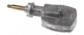
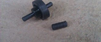
First you need to remove the old part. It is important to relieve pressure in the system by removing the fuse. If the fuse cannot be found, it is better to leave the car to stand with the engine turned off.
After removing the old injection pump, use a ruler to measure the length of the rod; on a worn part it is always less than normal. For example, for a Ford car the normal length will be about 22 mm. It is advisable to supply a new spare part, its installation is easier and it will last longer. When buying a used pump, you need to measure the rod; you should not buy it if the length is 5-7 mm less than the standard one. In this case, the pump will not work correctly.
Scratched stem
Adjusting the injection pump before installation
When the first plunger fires, you need to connect the plug to the connector with a positive charge. Next, you need to rotate the pump gear; it is adjusted according to the mark in the neutral position of the first plunger or displacer. When turned with a wrench, the position of the plunger changes. It can be moved to the right or left, then the key will rest. This means that the displacer is at its lowest point.
Plunger pair
The gear is turned so that the part without a tooth is located near the mark. The blind tooth should be on the left side of the flange. If you imagine that the gear represents a watch dial, then the mark without a tooth is at the 11 o'clock position.
General description of fuel injection pump assembly
Repair of Kamaz injection pump and diagnostics
Before assembling the injection pump, it is necessary to wash and troubleshoot. It is advisable to wash fuel pump parts and injector bodies in drum-type washers operating in a closed cycle. For the last 5 months, the author has been using a Geyser sink with a drum diameter of 700 mm.
When troubleshooting parts of the injection pump and regulator, the author recommends replacing the following spare parts when the plunger pairs are worn:
- 2 418 455 727 – Plunger pair – 8 pcs.;
- 2 418 459 037 – Discharge valve – 8 pcs.;
- 2 414 612 005 – Valve spring – 8 pcs.;
- 2 410 422 013 – Rotating sleeve of the plunger (if there is wear on the ball, look through an 8x magnifying glass);
- 2 417 010 022 – Complete fuel injection pump repair kit;
- 2 427 010 049 – Repair kit for fuel injection pump regulator;
- 2 421 015 057 – Regulator gasket;
- 2 447 010 043 – Repair kit for high pressure fuel pump valves.
When troubleshooting, pay attention to the working surfaces of the cam shaft, pushers, bearings and springs. The injection pump housing must be cleaned; before washing, all rings remaining after dismantling the plunger bushings must be removed
Figure 1.1 shows the tools for installing the plunger and pusher and fixing the pusher.
Figure 1.1 – Tool kit for installing and fixing the plunger
The position of the pusher lock is such that the catalog number indicated on the pusher body is located on top, and the 0 mark on the rotating part of the lock is on the bottom. Install and dismantle the pusher stoppers on fully depressed cams in order to prevent breakage of the stoppers.
The cam shaft should be installed as shown in Figure 1.2.
Figure 1.2 – Position of the camshaft cams when installing and removing the pusher stops
Install the cam shaft as shown in Figure 1.3.
Figure 1.3 – Installation of the injection pump cam shaft
It should be noted that on the fuel injection pump shown in the photo, it is more convenient to dismantle and install the cam shaft from the regulator side. Many models use tapered bearings, so dismantling the cam shaft should be done through the front part of the injection pump after removing the front HF bearing cover.
Dismantling and installation of the cam shaft into the fuel injection pump housing is carried out using a press or with light blows through a copper or aluminum adapter.
It is recommended to carry out all impact work with rubber hammers.
Use metal plugs only once.
Injection pump lubrication
It is best to connect the injection pump and regulator to the engine lubrication system, because With this form of lubrication, the injection pump remains maintenance-free. Filtered engine oil is supplied to the injection pump and regulator through the discharge line and the inlet channel through the roller tappet hole or using a special oil supply valve. In the case of a base or frame fuel injection pump, the lubricating oil is returned to the engine via the return line (b).
In the case of flange mounting, the return of lubricating oil can occur through the camshaft bearing(s) or through special channels. Before turning on the injection pump and regulator for the first time, they must be filled with the same oil as the engine. In the case of an injection pump without a direct connection to the engine oil system, oil is poured in through the cover after removing the air bleeder cap or filter. The oil level in the pump is checked by removing the oil level screw on the regulator at the intervals prescribed by the engine manufacturer for changing the engine oil. Excess oil (an increase in the amount due to oil leakage from the lubrication system) must be drained, and if there is not enough oil, then add fresh oil. When the injection pump is removed or when the engine undergoes major repairs, the lubricating oil must be replaced. To check the oil level, injection pumps and regulators with a separate oil supply are equipped with their own dipstick.
Controlling the moment when fuel supply starts
VAZ-2106, main brake cylinder operating principle, design, repair
The moment the fuel supply begins is regulated by a closed-loop electronic control system (feedback control system). An injector needle movement sensor installed in one of the injectors (usually in the first cylinder) sends a signal to the electronic control unit about the actual moment of fuel injection. This information is used to determine the actual injection start point in degrees of rotation of the engine crankshaft, which in turn can then be compared with the setting value of this value and subsequent adjustment is made according to the electrical signal sent to the fuel start actuator.
The actuator (drive) for starting fuel supply is “structurally rigid”. For this reason, you can dispense with a special feedback sensor. Structural rigidity means that the directions of action of the forces of the electromagnet and the spring always have a precisely defined point of intersection, that is, these forces are always in equilibrium. Thus, the linear movement of the electromagnet armature is proportional to the strength of the electric current, which is equivalent to the action of feedback in a closed-loop control system.
Disabling the injection pump for a long time
If the engine and, accordingly, the injection pump remain unmaintained for a long time, then no diesel fuel should remain in the injection pump, because Over time, it becomes thick and viscous, plungers and discharge valves can seize and even corrode. For this reason, before preservation, it is necessary to add approximately 10% of a suitable anti-rust agent to the fuel tank and in the same proportion to the oil in the injection pump camshaft chamber. The engine should then be started for approximately 15 minutes, during which all normal diesel fuel will be flushed out of the injection pump, which at the same time will be effectively protected from fuel thickening and corrosion. New injection pumps, which have already been effectively protected from corrosion at the factory, are marked with the letter “r”.
Source
Start of fuel supply
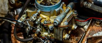
Device repair and adjustment of carburetor for 151C
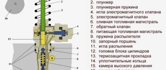
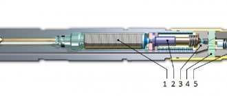
As soon as the plunger (position 7) completes the preliminary stroke h1, the control clutch 4 closes the control hole 6 in the plunger. From this moment, the pressure inside the high-pressure chamber 2 increases, and geometric fuel supply begins.
The moment at which the supply and, consequently, fuel injection begins, changes with the vertical movement of the control clutch relative to the plunger. When the control clutch is closer to the position of the plunger at TDC, the stroke of the plunger until the control hole 6 is blocked is greater, and the start of feed, therefore, occurs later, and when the control clutch is located closer to the BDC of the plunger, the stroke of the plunger until the hole is blocked is shorter, and the geometric the start of the feed occurs earlier.
The shape of the injection pump cam determines the stroke speed of the plunger and, accordingly, the nature of the fuel supply (theoretical amount of fuel supplied per degree of rotation of the injection pump camshaft), as well as the fuel injection pressure.
Adjusting the fuel injection pump on the engine
The fuel injection pump is synchronized with the engine using timing marks to start injection (closing the channel). These marks are located on the engine and on the fuel injection pump.
Typically, the engine's compression stroke is used as the basis (the reference point for injection timing adjustments, although other possibilities may be used for a particular engine model). In this regard, it is important that the manufacturer's instructions are taken into account. In most cases, the timing mark for closing the channel is located on the engine flywheel, on the V-belt pulley or on the vibration damper. There are several possibilities for adjusting the injection pump and setting the correct value for the start of injection (closing the channel).
- The fuel injection pump is delivered from the factory in a form where its cam shaft is locked in a predetermined position. After installing the injection pump on the engine and strengthening it with bolts, when the crankshaft is in the appropriate position, the cam shaft of the injection pump is released. This well-tested method is inexpensive and is becoming more and more popular.
- The injection pump is equipped with a channel closing indicator at the end of the regulator, which must be aligned with the installation marks when the injection pump is installed on the engine.
- The injection timing advance device (clutch) has a mark for closing the hole, which must be aligned with the mark on the injection pump body. This method is not as accurate as the two described earlier.
- After the fuel injection pump is installed on the engine, a high pressure flow method is used at one of the pump outlets to determine the point (moment) of channel closure (i.e., when the plunger closes the fuel outlet channel). This "wet" method is also being actively replaced by method 1 and 2 described earlier.
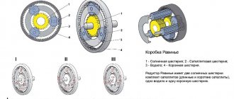
Operation of the injection pump plunger
When the plunger is positioned at bottom dead center (BDC) (1), the channels for fuel supply in the plunger sleeve are open. Through them, fuel under pressure created by the fuel priming pump from the fuel injection pump line enters the high-pressure chamber (section) (into the cavity of the liner above the plunger) (7). When the plunger moves upward, it rises to the fuel supply channel and blocks it with its upper end (8). This stroke of the plunger is called the preliminary stroke (2). As the plunger moves further, the fuel pressure increases and the discharge valve (9) opens. If a constant volume discharge valve is used, the plunger makes a further movement called the retraction stroke (3). During the effective (working) (4) stroke, fuel is supplied to the injectors through the high pressure fuel line. The power stroke ends as soon as the spiral groove of the plunger opens the drain channel (or fuel inlet channel) (10). From this moment, the fuel supply to the injectors stops, because with further movement of the plunger, the fuel passes through the vertical groove of the plunger back into the fuel line (idling) (5). As the plunger continues to move in the opposite direction (12) from top dead center (TDC) (6), fuel continues to flow through the vertical groove into the sleeve until the spiral groove of the plunger passes completely past the drain channel and it closes.
With further downward movement of the plunger, a vacuum appears in the sleeve above it, and as soon as the plunger opens the fuel inlet channel, fuel fills the sleeve above the plunger and the cycle can be repeated again. (A - general stroke).
One of the factors affecting diesel power is the amount of fuel injected. The task of the injection pump is to always accurately dose the appropriate amount of fuel depending on the load on the engine. The amount of fuel injected is changed by changing the stroke of the plunger. To do this, the control rack (5) rotates the pump plunger in the sleeve (1) so that the spiral groove (4), running diagonally around the circumference of the plunger, can open the fuel inlet channel (2) earlier or later and thus change the end of delivery and with it the amount of fuel injected. In the maximum flow position (c), the fuel channel does not open until the plunger has gone through its full stroke and has provided the maximum possible fuel flow. With medium flow (b), the fuel channel opens earlier depending on the exact position of the plunger. In the zero flow position (a), the vertical groove of the plunger is directly opposite the fuel inlet port. During this movement of the plunger, the high-pressure chamber is constantly connected to the fuel supply line through the vertical groove of the plunger. There is no fuel supply. The plunger rotates to this position when the engine is turned off.
In the in-line injection pump RE... .A, a gear rack is used to rotate the plunger and change the amount of fuel injected.
How to adjust the injection pump of a diesel engine with your own hands
There are two ways to adjust injection angles, which affect ignition quality, without a stand:
- according to previously set marks;
- selection
The first method of adjusting the injection pump with your own hands is faster and more convenient. However, if there are no other options, injection angles can be selected experimentally. Let's consider each option in more detail.
Adjusting injection angles according to marks
You can adjust the angles using the marks with your own hands for fuel injection pumps with a mechanical device. This method is not suitable for pumps with an electronic module. To adjust the injection advance, you need to rotate the injection pump around its axis. You can also rotate the camshaft pulley in relation to the hub.
To adjust the injection pump using this method, it is necessary that the pulley and the injection pump do not have a rigid connection.
To adjust, you will need to get to the rear of the diesel engine housing, where the casing and flywheel are located. To adjust the fuel injection pump yourself on some engines (KAMAZ 740, YaMZ 7511, Porter, Toyota, etc.), the casing will have to be dismantled first.
After this, you need to find the stopper on the flywheel, which is immersed in the slot. Next, you need to rotate the flywheel with your own hands (figuratively, of course, this will require a key or other tool convenient for you). The rotation of the flywheel causes the crankshaft of a diesel engine to rotate. You need to turn the flywheel clockwise until the stopper located on top engages.
After the stopper has been activated, you need to pay attention to the fuel pump drive shaft. If the scale on the coupling transmitting rotation is located in the upper position, then the mark on the fuel injection pump flange should be aligned with the zero mark of its drive.
Once you have aligned the marks, you can tighten the fasteners.
What should you do if, when adjusting the fuel injection pump yourself, the scale does not coincide with the drive marks? Then you need to lift the flywheel stopper and rotate it until the latch works again. Once the stopper has worked, you need to check the position of the scale again. It matches - you can fix the bolts. If not, another revolution of the flywheel is made.
The next step after tightening the drive clutch bolts is to turn the crankshaft 90 degrees after lifting the stopper. Once you have completed the turn, the stopper is placed back into the groove.
If you had to remove the casing to adjust the injection pump yourself, at this stage you can put it back in place.
To check the correct adjustment of the fuel injection pump of a diesel engine, perform the following steps:
- the engine starts;
- at idle there should be a soft and even sound without knocking or dips;
- if detonation beating is heard, the injection pump adjustment is performed again, repeating all the steps again.
If you are satisfied with the results of the idle test, proceed to the drive test. To do this you need:
- start the engine and warm it up to operating temperature;
- press the gas;
- look at the color of the exhaust.
If the exhaust is normal, then adjusting the fuel injection pump yourself can be considered completed. If the exhaust gases are bluish or black, then fuel injection is delayed and additional adjustment is needed.
How to adjust the fuel injection pump of a diesel engine using the selection method
To adjust the fuel pump yourself using the selection method, you must first install the pulley. After installing it, you need to start the engine. If it does not start, you need to turn the injection pump pulley 2-4 teeth in relation to the timing belt.
Once you have been able to start the engine, you need to listen to the sound it makes. If detonation beating is heard, you need to turn the injection pump pulley 1-2 teeth in the direction opposite to the direction of its rotation. If, after starting the engine, a bluish or black exhaust appears, the injection pump pulley must be turned 1 tooth in the direction of rotation.
If, after adjusting the injection pump yourself, you do not notice any improvements, you can try to change the situation by turning the pump around its axis. By rotating it, it is necessary to achieve high-quality exhaust and engine operation without knocking.
To adjust Bosch and others fuel injection pumps with your own hands, you can take a different route. To do this, perform the following manipulations:
- unscrew the tube connecting the pump to the injector of the 1st cylinder;
- a transparent hose of a similar cross-section is attached to the end of the tube and directed upwards;
- turn on the ignition and slightly turn the pump pulley;
- when the fuel in the transparent hose has risen to the top level, a mark is placed on the pulley;
- Then the shafts (camshaft and crankshaft) are set according to the marks.
At this stage, you need to check the fuel injection pump adjustment: if it was carried out correctly, the diesel engine will operate with a soft sound, stably and without jerking. If there are questions about the quality of engine operation and exhaust, the steps described above are repeated.
In simple cases, it is quite possible to adjust the injection pump of a diesel engine with your own hands. If this does not work, you should contact a service center to professionally adjust the pressure on the stand.
And in the event of a breakdown, it’s worth buying an injection pump for a JCB excavator or other special equipment.
Previously, we wrote about which KDM (combined road vehicles) are produced on the KamAZ chassis.
A new edition of the document on increasing recycling collection for special equipment is being prepared April 26, 2021
PJSC "AvtoKrAZ" increases production volumes August 16, 2013
France is ready to produce agricultural machinery in the Stavropol Territory May 19, 2014
New Cummins Zero Emission Diesel Engines Now in Series Production January 29, 2020
Crawler bulldozer: how to choose reliable equipment
What types of tractors are there: photos, classification and types
Adjusting high pressure fuel pumps
Regulation of the injection pump must be carried out on special stands by highly qualified specialists. When adjusting the pump, use the bench injectors or injectors with which the pump was installed on the engine, marking the number of each injector in accordance with the cylinder. Before checking and adjusting the high-pressure pump, all injectors (if engine injectors are used) must be carefully checked and adjusted on a special stand in accordance with the specifications for the given type and model of injectors. After adjusting the pump, each injector should be installed on a cylinder corresponding to the pump section that was adjusted together with that injector.
The overall performance of the pump plunger pairs can be assessed using bench injectors adjusted to an injection start pressure 1.8…2 times higher than the nominal one. If in this case the pump provides supply, then the plunger pairs are in normal condition.
***
Cycle feed adjustment
The main adjustment of the fuel pump is to adjust the quantity and uniformity of the cyclic supply at nominal mode. To do this, the injection pump rail (or the dispenser for a single-plunger pump) is installed with a special screw in the nominal flow position. At the nominal rotation speed, the cyclic flow of all sections is measured, monitoring the fuel level in the measuring tubes for each section of the pump.
To control the amount of cyclic flow across pump sections, glass graduated test tubes are used, mounted on a test bench and connected to the outlet fitting of the section, or (in modern stands) on a display that visually displays the cyclic flow across sections of the fuel injection pump being tested. The cyclic flow must comply with the specifications for the pump and be adjusted for the specific engine model.
Deviation by sections (unevenness of supply) is allowed no more than 3...5%. Otherwise, for pumps of the 33 (KAMAZ) and 60 (ZIL) series, loosen the fastening of the section housing and turn it, moving the housing lock washer by one or two teeth. Some pumps (4UTNM, YAZDA, ChTZ) have special clamps for fastening sections, which, if necessary, loosen and correct the cyclic flow by turning the section body.
Adjusting the feed start angle
This angle is checked and adjusted on a bench.
In in-line pumps, a momentoscope is installed on the first section, and in V-shaped pumps of the 33 series - on the eighth section - a glass tube connected through a rubber pipe to a high-pressure fuel line (see figure). The rack is set to the nominal feed position and by manually rotating the pump shaft (by the injection advance clutch), the momentoscope tube is filled with fuel. By turning the shaft back and then slowly rotating it forward, determine the moment when the fuel surface (meniscus) in the momentoscope tube shakes. The rotation is stopped. In this case, the dial of the stand will show the angle to the axis of symmetry of the plunger drive cam. This angle must be within the specifications for that particular pump. So, for the eighth section of a series 33 pump (KAMAZ), this angle should be 42...43˚, and for the first section of 4UTNM pumps - 56˚.
After checking the first (or eighth) section, the torque scope is installed on the remaining sections according to the order of operation of the engine cylinders. The deviation of the injection advance angles by sections should not exceed 20′.
In order to adjust the advance angle of the start of flow in series 33 pumps (KAMAZ), the pusher heel is replaced, which is produced in 18 repair sizes. In pumps such as UTNM, TN, YAZDA, the plunger pusher screw is moved for these purposes. After adjusting the section, this screw is locked with a lock nut.
***
Academic disciplines
- Engineering graphics
- MDK.01.01. "Car design"
- General structure of the car
- car engine
- Car transmission
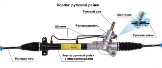
- Steering
- Brake system
- Suspension
- Wheels
- Body
- Car electrical equipment
- Basic car theory
- Basics of technical diagnostics
- Fundamentals of hydraulics and heat engineering
- Metrology and standardization
- Agreecultural machines. Agreecultural equipment
- Basics of agronomy
- Transportation of dangerous goods
- Materials Science
- Management
- Technical mechanics
- Tips for graduate student
Olympics and tests
- "Engineering graphics"
- "Technical Mechanics"
- "Engine and its systems"
- "Car chassis"
- "Car electrical equipment"
Types of injection pump
Injection pumps are separated by the method of fuel injection. It can be produced by a battery injection system or using a plunger. The main element of the pump is a part such as a plunger pair, which visually represents a piston with a cylinder. Fuel is supplied inside the cylinder. Then it is pushed out through the inlet valve by a plunger. Various technologies use several structurally different pumps:
- distribution The design of the unit has one or a pair of plungers that pump fuel through the cylinders;
- in-line. These pumps have only one plunger design;
- mainline This pump pumps fuel into the battery.
Any equipment, even imported and the most reliable, can fail. As a rule, the earlier a breakdown is detected, the more inexpensive means it can be solved. If the repair procedure is not carried out immediately, then a failed pump element can affect the working mechanisms of the entire power unit, and this breakdown will lead to a major overhaul. Each manufacturer sets a certain service life in the passport, and if the operating rules and technical inspection periods are observed, the need for major repairs may not arise. If you neglect the timing and the need for periodic inspection and operate the car even if a malfunction occurs, it will not last up to the period recommended by the manufacturer and will require expensive major repairs.
The main reasons for the increase in diesel fuel consumption
The main reasons for increased fuel consumption on diesel engines and the occurrence of smoky exhaust include:
- lack of tightness of the power supply system;
- air filter clogged;
- clogged fuel drain line;
- contamination or wear of injectors;
- violation of the fuel injection advance angle depending on the rotation speed;
- clearances in the valve mechanism;
- failure of the high pressure fuel pump.
Some of these reasons simultaneously lead to a decrease in power, deterioration in acceleration dynamics, unstable operation of the engine at idle, and problems with starting.
Preparatory and verification operations
Injection pump marking
The range of VE fuel pumps is determined by the type of diesel engines on which they are installed, and the basic data of the pump is reflected on the company plate shown for one pump as an example in the figure.
Rice. Nameplate designating the injection pump model VE
The brand of pump VE 4/9 F2250R12 is deciphered as follows:
- V—distribution type pump;
- E - denotes the fuel injection pump family;
- 4 - number of engine cylinders;
- 9 — diameter of the pump plunger, mm;
- F - indicates the type of regulator - centrifugal;
- 2250 — rated pump shaft rotation speed, min-1;
- L — left-hand rotation pump (R — right-hand rotation pump);
- 12 — performance index (for this diesel engine).
Additional digital designations on the plate are company indices, for example, 0 460 494 001 is deciphered as follows: 0 - production index, 460 - product class, 4 - indicates a VE type pump, 9 - plunger diameter index. 4 is the number of diesel cylinders, 001 is a serial number that may change during production.
In Japanese-made VE fuel pumps, the abbreviation “NP” is added to the designation, for example, VE 4/8 F 2500 LNP 347.
In addition, the nameplate may indicate the company (ZEXEL), and the same name is cast along with the pump housing.
The performer index in the pump designation can be specified depending on the configuration, so for the VW “AAZ” diesel we have:
- Bosch VE 4/9 F2300 R 432 - car without air conditioning;
- Bosch VE 4/9 F2300 R 432-4 - with air conditioning.
General verification methods
Despite the wide range of VE pumps and some design differences, there are general methods for checking and adjusting the injection pumps under consideration. Below are some techniques for simple checks of fuel equipment in the event of a diesel engine malfunction.
If there are missed flashes in individual diesel cylinders, uneven operation and loss of power associated with this malfunction, then to determine the cylinder operating intermittently, the method of sequentially turning them off at the minimum idle speed can be used. To do this, unscrew the nut securing the high-pressure pipe to the injector half a turn and determine by ear or using a tachometer the presence or absence of changes in engine operation. If there is no change in operation, this cylinder is the cause of uneven operation and, therefore, a more detailed check is required (injectors, compression, etc.).
Analysis of exhaust smoke is useful in determining the causes of diesel engine malfunctions.
Rough operation and loss of power may be due to clogged fuel suction lines with dirt or air leaks. The presence of bubbles in the inlet can be determined by installing a transparent tube on the suction line.
If the diesel engine does not develop maximum speed and there are signs of fuel supply problems, you should install a pressure gauge on the union of the fine fuel filter and check the low pressure value, which must correspond to the company specifications. You should also check the condition of the fuel filter and whether there is excess water in the filter separator.
It is necessary to check the injection pump drive. to ensure that the injection timing is set correctly, especially if the engine has been repaired.
One of the first checks should be to ensure the correct connections between the governor control lever and the accelerator pedal. To do this, there must be a correspondence between the maximum idle speed and the start of operation of the regulator with the drive disconnected from the pedal, i.e. when directly acting on the control lever, and with it connected. If there is any discrepancy, adjust the drive.
An important parameter for the operation of the fuel system is the temperature of the fuel in the internal cavity of the injection pump housing, the optimal value of which should be within 45 - 50 ° C. An increase in temperature above 50°C leads to a decrease in diesel power, to a greater extent for a turbocharged engine.
How to set injection timing on a diesel engine
Greetings to all readers of my blog. So I decided to share my experience in setting injection timing on AAZ and AEY (M-TDI) diesel engines. And so, let’s say that you have a diesel engine with a mechanical injection pump (VAG family), which is missing a timing belt and the timing marks are knocked off. Something like this :-).
Naturally, you begin to digest a bunch of information received from technical books and forums. And we learned that you will need special devices for this, namely: a bar for fixing the camshaft, a roller for fixing the injection pump pulley and a dial-type micrometric indicator for setting the injection moment. And these devices are really needed. But there is one “BUT”, we don’t have them at the moment, and the engine needs to be started. And so, how do we install the timing belt and injection timing if there are no tools? First, we need to set up the gas distribution mechanism. Let's start with the camshaft. We turn the camshaft so that the cams of the first cylinder look up, and the slot on the back side of the camshaft end should be parallel to the cylinder head housing.
Then we set the piston of the first cylinder to TDC; to do this, we align the mark (0) on the CV flywheel with the mark in the gearbox window. If there is no gearbox, then divide the distance between the bolt holes (on top) by floors, put a mark on the block, this will be TDC. Combine (0) with this label.
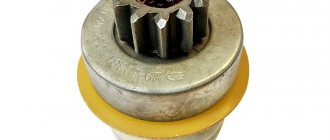
Next is the fuel pump. To install the injection pump at the moment of injection of the first injector, we need to align the smallest hole in the injection pump gear with the hole in the injection pump bracket.
It will not be possible to align them exactly because of the pair spring in the injection pump housing. So the pulley will move counterclockwise by one tooth. But it's not scary. Let's continue further. We install the timing belt on the HF gear, bring it to the injection pump gear, use a 19 key, carefully turn the injection pump gear clockwise by one tooth (make sure the holes match), put the belt on the injection pump gear. After which we carefully remove the key, the injection pump gear, under the action of the spring, moves one tooth counterclockwise, the mark (0) KV also moves one tooth. Next, we bring the timing belt to the camshaft gear, but before putting the belt on, we need to turn the camshaft gear one tooth counterclockwise, after which we tighten the belt and tighten it with a tension roller.
We return the mark (0) to its place and see that all the marks are in place as they should :-).
Next, we set the injection moment of the injection pump; to do this, you need to align the marks on the injection pump and its gears.
We align the marks in the following way; all timing marks must remain in their places. We align the marks by moving the injection pump housing, and the gear remains in place. After which the injection pump tightens. And everything is ready :-), you can start the engine :-). When checked repeatedly with a dial indicator, the injection moment is within 0.84-0.92.
That's basically it :-). Thank you for your attention :-). Good luck to all :-).
It happens that after replacing the timing belt (timing belt) or fuel pump (fuel pump) on a diesel engine, it is difficult to find the marks by which you need to align the fuel injection pump pulley to ensure timely fuel supply. What should I do?
You can, of course, try to “catch” the required position of the fuel pump pulley using the “scientific poke” method, i.e. put it in one position and try to start the engine.
If it doesn’t start, turn the injection pump pulley 3-5 teeth relative to the timing belt in any direction and try again.