Box modifications
The type of box installed depends on the loads the vehicle experiences and the conditions in which it is operated:
- KPP-14;
- KPP-15;
- KPP-16;
- KamAZ ZF gearbox.
The fourteenth transmission is a five-speed device, which includes a gearbox. The fifteenth modification of the product with ten stages, unlike KamAZ-14, is equipped with a divider with two stages, the device is located in the front part of the box.
Gearbox KamAZ-14:
Transmissions are controlled mechanically, remotely, using a swing lever located on the power plant. The mechanical gearbox is controlled by pneumatics and mechanics, through a selector. The driver directly acts on the rocker.
The sixteenth gearbox, with eight shift stages, is of mechanical type. The design includes a four-stage gearbox and a reduction box mounted behind the structure.
The base of the rod that switches the stages is installed on the gearbox plug; the lever itself is made in an original design solution. The product contains a rod that controls the gearbox, a lever, a safety net that prevents erroneous start of reverse, and valves controlled by pneumatics and switching a mechanism that increases torque.
Gearbox KamAZ - 15:
The ZF gearbox on KamAZ with nine stages is equipped with an auxiliary reduction gear, unlike the 16 model.
The KamAZ 5320 gearbox is equipped with five stages. Since the equipment is operated in harsh conditions, it is equipped with large gear ratios for operation at low speeds. Switching occurs in stages, the transmission easily adapts to road conditions.
KamAZ ZF gearbox:
Gear controls on modern cars are different. A mechanism with fewer gears is used on vehicles with a smaller load capacity and dimensions. Modifications of 10 stages are installed on road trains. KamAZ is in demand in 40 countries because the control mechanisms are reliable and durable.
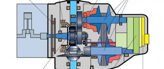
Design and principle of operation of the gearbox
The main components that make up the KamAZ transmission unit:
- Crankcase device. It uses three shafts - primary, secondary and intermediate. Purpose of the gear module: activation of reverse speed.
- Upper protective cover of the gearbox.
- The gear shift mechanism itself (a collapsible device).
- Engine located on the front of the crankcase.
On KamAZ dump trucks, when switching from high speed to low speed, the rocker is not used. This feature of trucks with European standards Euro 2, 3 and 4 implies the use of a special switch and clutch pedal. Switching is done automatically. In accordance with the official description in the technical manual for use and maintenance, the upper position of the selector is necessary for a loaded car, and the lower position for an empty car.
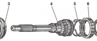
Drawing of the KamAZ 14 transmission design drawing
A more detailed diagram of the gearbox design of KamAZ trucks using the example of model 14:
- Drive shaft.
- Rear bearing element protective cover for drive shaft.
- Adjusting shim.
- Handle rod.
- Protective ring.
- Handle support cover.
- Handle support block.
- Sealing gasket.
- Rod support.
- Spring element.
- Gear shift knob support.
- Module axis with reverse gears.
- Thrust washer.
- Reverse gear module.
- Roller bearing.
- Screw with pin.
- Lock washer.
- Top cover.
- Sealing rubber.
- Rear bearing cover for driven shaft.
- Retaining ring.
- Rear ball bearing element for traction of the driven shaft.
- Adjusting shim.
- The so-called worm connected to the speedometer drive.
- Sealing collar.
- Flange fixing nut.
- Flange for fixing the cardan shaft.
- Cup of the rear bearing device of the intermediate shaft.
- Bearing device cover.
- Roller bearing.
- Thrust washer.
- Sealing rubber.
- Intermediate shaft.
- Crankcase device of the transmission unit.
- Driven shaft.
- Sealing rubber.
- Front bearing cover located on the intermediate shaft.
- Crankcase device of the clutch system.
- Sealing collar.
- Clutch release fork.
- Clutch release fork shaft.
- Clutch system coupling.
Five-speed gearboxes are installed on cars intended for individual use, while trucks belonging to the class of road trains are equipped with ten-speed units. By design, the 10-speed unit is a box with five steps, complemented by a gearbox with a divider. This system provides the ability to use 10 forward speeds and two reverse.
If a model 152 or 154 transmission is installed on a new or old KamAZ, then it has the following differences from older versions:
- the gearbox is equipped with a reinforced synchronizer for the dividing mechanism;
- in such units the splines are more reinforced, and the fastenings of these elements are removed from the gearbox device;
- in newer versions on models 43118, 5320 and others, a different method of attaching the gears of the unit is used;
- The height of the gearbox teeth has been increased.
In a more modernized version of the KamAZ gearbox, the correct procedure for controlling and activating the dividing mechanism is carried out using a pneumatic device.
With divider
By design, the divider consists of the following elements:
- Spool valve. This component is used to control the gearbox and is located on the gear shift lever support. The node can operate in direct or reduced transmission modes.
- Pressure reducing valve. This element is used to extract compressed air coming from the pneumatic mechanism. The valve bleeds the air flow when the pressure in the system is critically high. From the pressure reducing valve, air is supplied to the control valve and the divider activation valve. This scheme allows you to create two circuits simultaneously in the car’s engine control system.
- Dividing mechanism activation valve. This device is designed to supply compressed air to the unit if the driver disengages the clutch. This principle of operation allows you to turn on and off a lower gear in parallel with changing gears on the main transmission.
- Divider gear shift mechanism. The device consists of a piston located in a cylindrical element. The piston rod is connected to a handle located on the mechanism fork shaft. If a compressed air stream enters the gearbox, the piston moves in a certain direction. As a result of the displacement, the operating mode changes.
- Divider air distribution line. This element is used to supply air to the box cylinder.
- Bearing elements, synchronizers and a crankcase equipped with shafts with gears.
Transmission unit with dividing mechanism
The device of a gearbox with a divider includes the following elements:
- Nut M12x1.25-6N.
- Lock washer marking 12.3.
- Protective cover for the front bearing device located on the intermediate shaft.
- Lock washer for 10.
- Screw M10x1.25.
- Protective cover of the front bearing device located on the input shaft, assembled.
- Seal rubber for the input shaft cover.
- Adjusting shim.
- Adjusting shim.
- Primary shaft of the dividing device assembly.
- Special nut M52x2-L-6N.
- Oil injection ring located on the input shaft.
- Pin class 4x12.
- A radial-type roller bearing device with elongated double-row cylindrical rollers is not equipped with rings.
- Retaining ring.
- The roller bearing device is of radial type and belongs to the category of single-row devices.
- Primary shaft of the transmission dividing mechanism.
- Parallel key.
- Rear bearing element bushing located on the input shaft.
- Gear of the input shaft of the transmission dividing device assembly.
- Drain plug equipped with a magnet to attract wear debris.
- Divider crankcase assembly with bushings assembled.
- Oil can.
- Eye bolt.
- Stub.
- Sealing rubber.
- Screw M8-6gx16.
- Spring washer.
- Hatch cover of the crankcase divider device.
- Crankcase stud M16x1.
- Spring washer.
- Nut standard M16.
- Synchronizer unit for the gearbox dividing mechanism assembly.
- Gasket for crankcase divider device.
- Intermediate shaft.
- The socket of the rear bearing device located on the intermediate shaft.
- Bolt M6.
- Roller bearing element.
- Clutch housing cover located on top.
- Intermediate shaft of the dividing device.
- Intermediate shaft gear.
- Dividing unit of the box with control mechanism assembly.
- Pin 12x35.
- M16 hairpin.
- Radial-type ball bearing element belonging to the single-row class. The device is equipped with a groove and is located on the outer ring.
- Front bearing thrust ring.
- Thrust washer.
- Hairpin M12x1.
- Retaining bar.
- Screw M12x1.25.
- Gasket for the front bearing element cover located on the intermediate shaft.
- Bearing cap seal ring.
- Protective cover for the inspection hole located at the bottom.
- Clutch housing cover.
The main feature of transmissions on KamAZ Euro 2, 3 and 4 is the ability to operate in high or low mode. This feature was provided by the developers to minimize the load on the engine of the machine, which can move both unloaded and loaded. The dividing device is a mechanical gear unit designed to increase the gear ratio.
Transmission diagrams
The following gearboxes are used on KamAZ vehicles today:
- model 14;
- Model 15 transmissions;
- Checkpoint 161;
- ZF transmissions manufactured in Germany.
Model 14
Gearbox Features:
- cars operating “mechanically” of the new model 14 have modifications 141, 142 and 144;
- such systems belong to the category of five-speed units in which three-code switching mechanisms are located;
- gears are switched on remotely using a rocker lever;
- Such boxes can be used on dump trucks, as well as single vehicles without trailers.
These gearboxes can be used on the following models:
- 53215;
- 53212;
- 55111;
- 5311;
- 43114;
- 5410;
- 5320;
- 55102;
- 4308;
- 4310 etc.
Table: gear ratios of KamAZ 14 model gearboxes
| Model | 1 speed | 2 speed | 3 speed | 4 speed | 5 speed | R |
| Model 141 | 5,62 | 2,89 | 1,64 | 1,00 | 0,724 | 5,30 |
| Model 142 | 6,38 | 3,29 | 2,04 | 1,25 | 0,815 | 6,02 |
| Model 144 | 7,82 | 4,03 | 2,5 | 1,53 | 1,00 | 7,38 |
Model 15
Features of 15 models:
- such transmissions have modifications 152 and 154 and belong to the category of ten-speed units;
- the device includes a five-speed gearbox and a two-speed engine located at the front;
- the presence of a dividing mechanism increases the number of speeds to 12 (10 forward and 2 rear)4
- Gear shifting is done remotely using a rocker lever, and the divider is switched on pneumomechanically (using a switch on the handle);
- Basically, such a gearbox is found on tractors operating as part of road trains.
These transmissions can be used on models:
- 53215;
- 44108;
- 53212;
- 55111;
- 65115;
- 5311;
- 43114;
- 43118;
- 5350;
- 5410;
- 5320;
- 55102;
- 5511 etc.
Talitsa: gear ratios of KamAZ 15 model gearboxes
| Model | 1 speed | 2 speed | 3 speed | 4 speed | 5 speed | R | |
| Model 152 | Increased | 7,82 | 4,03 | 2,5 | 1,53 | 1,00 | 7,38 |
| Reduced | 6,38 | 3,29 | 2,04 | 1,25 | 0,815 | 6,38 | |
| Model 154 | Increased | 7,82 | 4,03 | 2,5 | 1,53 | 1,00 | 7,38 |
| Reduced | 6,38 | 3,29 | 2,04 | 1,25 | 0,815 | 6,38 | |
Model 161
Model 161 belongs to the class of eight-speed transmissions, which includes a 4-speed gearbox, as well as a rear-mounted planetary two-stage range. The latter is used to enable reduced and forward speeds.
These devices are mainly used on models:
- 6350;
- 6450.
However, installation is also possible on KamAZ trucks equipped with 740.50-360 or 740.51-320 engines.
Table: gear ratios of KamAZ 16 model gearboxes
| Model | 1 speed | 2 speed | 3 speed | 4 speed | 5 speed | 6 speed | 7 speed | 8 speed | R |
| Model 161 | 8,39 | 5,50 | 3,93 | 2,87 | 2,12 | 1,40 | 1,00 | 0,73 | 11,01 |
Model ZF
ZF transmissions include several types of gearboxes in their lineup:
- ZF-6S1000 (16-speed manual);
- ZF-9S109 (the nine-speed manual transmission looks like the 161 model, equipped with an additional reduced speed);
- ZF-9S1310 (mechanical “nine-speed”);
- ZF-16S151 (sixteen-speed gearbox, including an eight-speed unit and a two-stage range).
Checkpoint data can be used on:
- 44108;
- 65115;
- 43114;
- 43118;
- 6520;
- 6460;
- 6522;
- 65225;
- 65117;
- 5490 etc.
Table: gear ratios of KamAZ ZF model gearboxes
| Model | 1 speed | 2 speed | 3 speed | 4 speed | 5 speed | 6 speed | 7 speed | 8 speed | 9 speed | R | |
| ZF-6S1000 | 10,24 | 6,576 | 4,78 | 3,531 | 2,61 | 1,86 | 1,35 | 1,0 | 0,74 | 9,44 | |
| ZF-9S109 | 6,75 | 3,60 | 2,12 | 1,39 | 1,00 | 0,78 | 6,06 | ||||
| ZF-9S1310 | Increased | 13,80 | 9,59 | 6,81 | 4,58 | 3,021 | 2,09 | 1,49 | 1,00 | 13,17 | |
| Reduced | 11,55 | 8,02 | 5,70 | 3,84 | 2,52 | 1,75 | 1,24 | 0,84 | 11,03 | ||
| ZF-16S151 | 9,48 | 6,58 | 4,68 | 3,48 | 2,62 | 1,89 | 1,35 | 1,00 | 0,75 | 8,97 | |
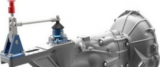
Photo of KamAZ checkpoint
Gearbox KamAZ 14
Model 15 transmission unit
Box 161 removed
Transmission unit KamAZ ZF
Description of gearboxes
Structurally, the ten-speed transmission is a box with five steps and a gearbox. This design uses 10 forward gears and 2 reverse gears. The transmission is popular and is used for installation on vehicles carrying heavy loads. The mechanism received index 15.
Distinctive features of the KamAZ-15 box:
- Used in conjunction with a reinforced divider synchronizer;
- The splines have been modernized and strengthened, the fastening parts have been removed from the box;
- The fixation of transmission gears has been modernized;
- The height of the teeth has been increased.
Downshift (divider) valve for KamAZ-15:
The pneumatic system activates and controls the KamAZ transmission dividing device. The performance and durability of the unit directly depends on the correct use of this unit. For the same reason, inspection of the KamAZ transmission is carried out at specialized stations.
KamAZ transmission elements:
- Box body with built-in shafts: driving, driven, intermediate;
- Gear mechanism for activating reverse;
- Upper casing;
- Collapsible mechanism that switches stages;
- The power unit is located in the front of the body.
Box divider
High and low operating modes, a feature of KamAZ gearboxes. This specificity is caused by the desire to reduce the load on the power plant. It is typical that it does not matter whether the machine is loaded or not. A divider is a gearbox based on the principle of mechanics and increases gear ratios. The mechanism is started using a switch on the rocker.
The design includes:
KamAZ-15 box divider input shaft:
- The valve that controls the device. The part is attached to the base of the switch, uses direct and reduced speed modes.
- A valve that maintains a constant outlet pressure. It takes compressed air and resets the pressure in the system when the established values are exceeded. Transfers air to the control valve and to the valve of the dividing device from the air unit. Thanks to manipulations, there are simultaneously two circuits in the engine control system.
- Divider activation valve. Supplies air pressure to the device when the clutch is disconnected. This engages and disengages low gear, paralleling the transmission's gear changes.
- Dividing mechanism. The composition includes a piston placed inside a cylinder. The piston lever is connected to a rod fixed to the fork shaft of the assembly. When air pressure hits, the piston moves, this changes the operating mode of the box.
- The air distribution pipe supplies air pressure to the cylinder of the unit.
Gearbox modifications
Summary data from the manufacturer's catalog on the applicability of each basic model:
Gearbox 14 KAMAZ
Discontinued from production, replaced by KP 142. Type - mechanical, without increased or decreased. Gear ratios: 7.62 – 1.0.
Weight, net, kg: 252
Applicability: 5320, 5410, 4310, 43101
Gearbox 141 KAMAZ
For cars with engines with torque up to 850 Nm. Installed on single and bus chassis. Type – mechanical, without increased or decreased. Gear ratios: 5.62 – 0.724. Weight, net, kg: 250
Applicability: Ural 4320, KAMAZ 43253, 43505, 4308
Gearbox 142 KAMAZ
It is produced to replace the KP 14, has many modifications for a conventional clutch and a single-disc clutch (MFZ 430). For cars with engines with torque up to 850 Nm. Type – mechanical, without increased or decreased. Gear ratios: 6.38 – 0.815. Weight, net, kg: 254
Applicability: 43114, 43118, 43253
Gearbox 15 KAMAZ
Out of production, replaced by KP 152. Torque up to 667 Nm. Type – mechanical, with divider. Gear ratios: 7.82 – 0.815. Weight, net, kg: 268
Applicability: 5410, 5511, 5320, 53212, 55102
Gearbox 152 KAMAZ
Produced to replace the 15th, the manufacturer strengthened the splines of the input shaft of the divider, the clutch of the input shaft gear and the divider synchronizer, and used a keyless connection between the gear and the intermediate shaft. Despite the usual design, it is found with a single-plate clutch. There is a modification for docking with the YaMZ engine (on MAZ). Torque up to 850 Nm. Type – mechanical, with divider. Gear ratios: 7.82 – 0.815. Weight, net, kg: 272
Applicability: 55111, 53212, 53215, 54105, 4326, 43114, 43118, 43253
Gearbox 154 KAMAZ
Focused on traction parameters, withstands torque up to 1100 Nm, and is widely used on all-wheel drive 6x6 all-terrain trucks. 10-speed, with a single-plate clutch; if desired, you can install it instead of the ZF 9S gearbox by replacing the cardan shaft and one driven disk. Type – mechanical, with divider. Gear ratios: 7.82 – 0.815. Weight, net, kg: 330
Applicability: 43118, 4350, 43505, 5350, 65115, 53605, 43114
Gearbox ZF 16S151 / 16S1820 TO
Designed for heavy-duty KAMAZ chassis, dump trucks and long-haul vehicles, withstands torque up to 1850 Nm. Initially produced as model 16S 151, it is currently produced under the designation 16S 1820. Type - mechanical, with a planetary range and a mechanical divider. , collected in Naberezhnye Chelny. Weight, net, kg: 290
Applicability: 6350, 6450, 6520, 65221, 65225, 5460.
Modifications:
- 1341.002.073 and 1341.002.074 – standard version
- 1341.002.075 and 1341.002.075 – sealed
Gear ratios
| Transfer number | Gear |
| 1 | 13,74 |
| 2 | 11,54 |
| 3 | 9,44 |
| 4 | 7,93 |
| 5 | 6,5 |
| 6 | 5,46 |
| 7 | 4,57 |
| 8 | 3,84 |
| 9 | 3,01 |
| 10 | 2,53 |
| 11 | 2,07 |
| 12 | 1,74 |
| 13 | 1,42 |
| 14 | 1,2 |
| 15 | 1,0 |
| 16 | 0,84 |
| 3X1 | 12,86 |
| 3X2 | 10,8 |
Gearbox ZF 9S1310 TO
An economical transmission from the Ecomid series, withstanding a torque of up to 1300 Nm, is installed on chassis, dump trucks, and KamAZ medium-duty transport vehicles. 9-speed, with a single-plate clutch; if desired, you can install it instead of the 154 gearbox by replacing the cardan shaft and one driven disk. Type – mechanical, with a range multiplier. , collected in Naberezhnye Chelny. Weight, net, kg: 190
Applicability: 65115, 65116, 65117, 53605, 5308.
Standard modification – 1324.001.098
Gear ratios
| Transfer number | Gear |
| Crawler | 9.48 |
| 1 | 6.58 |
| 2 | 4.68 |
| 3 | 3.48 |
| 4 | 2.62 |
| 5 | 1.89 |
| 6 | 1.35 |
| 7 | 1.00 |
| 8 | 0.75 |
| R | 8.97 |
Technical parameters of KamAZ gearboxes
The transmission of KamAZ vehicles is equipped with gearboxes that differ in gear ratios. For this reason, cars are used in many areas. The gear ratios are shown in the table below.
| Box modification | Gear/gear ratios | ||||||||||
| 1 | 2 | 3 | 4 | 5 | 6 | 7 | 8 | 9 | Reverse | ||
| 141 | 5,62 | 2,89 | 1,64 | 1,00 | 0,724 | – | – | – | – | 5,30 | |
| 142 | 6,38 | 3,29 | 2,04 | 1,25 | 0,815 | – | – | – | – | 6,02 | |
| 144 | 7,82 | 4,03 | 2,5 | 1,53 | 1,00 | – | – | – | – | 7,38 | |
| 152 | Increased | 7,82 | 4,03 | 2,5 | 1,53 | 1,00 | – | – | – | – | 7,38 |
| Reduced | 6,38 | 3,29 | 2,04 | 1,25 | 0,815 | – | – | – | – | 6,02 | |
| 154 | Increased | 7,82 | 4,03 | 2,5 | 1,53 | 1,00 | – | – | – | – | 7,38 |
| Reduced | 6,38 | 3,29 | 2,04 | 1,25 | 0,815 | – | – | – | – | 6,02 | |
| 161 | 8,39 | 5,50 | 3,93 | 2,87 | 2,12 | 1,40 | 1,00 | 0,73 | – | 11,01 | |
| ZF-9S109 | 10.24 | 6.576 | 4.78 | 3.531 | 2.61 | 1.86 | 1.35 | 1.0 | 0.74 | 9.44 | |
| ZF-6S1000 | 6.75 | 3.60 | 2.12 | 1.39 | 1.00 | 0.78 | – | – | – | 6.06 | |
| ZF-16S151 | Increased | 13.80 | 9.59 | 6.81 | 4.58 | 3.021 | 2.09 | 1.49 | 1.00 | – | 13.17 |
| Reduced | 11.55 | 8.02 | 5.70 | 3.84 | 2.52 | 1.75 | 1.24 | 0.84 | – | 11.03 | |
| ZF-9S1310 | 9.48 | 6.58 | 4.68 | 3.48 | 2.62 | 1.89 | 1.35 | 1.00 | 0.75 | 8.97 | |
In addition to gear ratios, the characteristics of the box modifications differ structurally. Thus, some models are equipped with parts and components that are not available in other modifications. ZF transmissions are assembled at the Russian plant, together with German partners, at the ZF-KAMA plant in Naberezhnye Chelny.
Gearbox control
Shift gears in the gearbox using the gear lever located to the right of the driver's seat. Change gears with the clutch disengaged. Press the clutch pedal all the way. Engage and shift gears at minimum idle speed. Start driving only from first gear (to avoid premature clutch failure). To quickly accelerate the vehicle on good roads and in difficult conditions, it is recommended to use all gears sequentially according to gear shift patterns. In cars with a cable drive to control the gear shift mechanism, a gearbox with a servo shift is used. The servoshift serves to facilitate gear shifting; air is supplied to it from the car's pneumatic system.
Attention! Do not change gears until the operating pressure in the pneumatic drive is reached (from 6.5 to 8.0 kgf/cm2) to avoid cable breakage due to the servoshift not developing the required force.
If there is a divider in the gearbox, a gear divider control switch is mounted in the gear shift lever handle (see Fig. Gear shift lever). The switch can be used to select the highest “B” or lowest “H” gear in the divider. It is recommended to use the entire range of low and high gears. To switch from a higher gear to a lower one, and vice versa (without shifting the lever), you need to move the gear divider control switch to the desired position, and then press and release the clutch pedal after a short (1 second) delay - the gear will engage automatically. To simultaneously shift the lever and engage a higher or lower gear, set the divider control switch to the “B” or “H” position, press the clutch pedal and shift the lever.
Gear shift lever
For gearboxes of models 144, 154, shift gears according to the diagrams (see Fig. Gear shift diagram in a model 144 gearbox and Gear shift diagram in a model 154 gearbox).
Shift diagram for a 144 transmission
Shift diagram for a 154 transmission
For the ZF 9S1310 model gearbox, shift gears according to the diagram (see Fig. Gear shift diagram in the ZF 9S1310 model gearbox):
- 1-2-3-4-lower gears (lowest range of multiplier);
- 5-6-7-8-high gears (highest range of range).
When slowing down, change gears only sequentially: 8-7-6-5-4-3-2-1. Always keep the gear engaged when driving.
Gear shift diagram in the gearbox model ZF 9S1310
Low gear “C” is intended for starting in difficult road conditions and for maneuvering.
Attention! For gearboxes it is strictly prohibited:
- switch from the highest range of the multiplier to the lower range of the multiplier at a speed of more than 30 km/h (for ZF gearboxes);
- move with the gear shift lever in neutral position;
- engage reverse gear (R) when the vehicle is not completely stopped and when the clutch plate is rotating.
Gear shifting in the multiplier occurs automatically: the highest gear is engaged when the gearbox control lever moves from the fourth to the fifth position, the lowest gear is engaged when switching from fifth to fourth. When the lever is moved through the “◊” position, the valve is activated, providing automatic switching of the range multiplier. When the low range is turned on in the range multiplier, a warning lamp lights up on the instrument panel. When the range shifter is switched, the gear shift lever rod of the main box is blocked, and a force is felt on the lever, after which it is recommended to wait 1-1.5 seconds to ensure the gear shift in the range shifter.
Start
The movement starts from the lowest level. The speed change is performed only with the clutch depressed, in several stages. The pattern is associated with upshifts and downshifts, which makes it possible to use the car on different surfaces and terrain.
A successful scheme is considered to be switching 1B-2B-3B when picking up speed, 4H-4B-5H when driving further. When starting, the shaft speed is increased to 7000 min-1, second gear is used after 3000 min-1. The correct operation of the gearbox and its durability depend on strict adherence to the regime on KamAZ 65115 and others. The correct modes reduce fuel consumption, make driving more economical, and extend the life of the power plant.
Gearbox KamAZ 4310 shift diagram:
Dismantling KamAZ gearbox
Disassembling the Kama Z gearbox :
- disconnect divider 4 (see Fig. 136) or clutch housing 38 (see Fig. 128) from the gearbox;
- disassemble the main gearbox in the following order: unscrew the bolts securing the upper cover 18 of the gearbox and, screwing two bolts into the special threaded holes in the cover (after having unscrewed the plugs from them), remove it; unscrew the nut 26 securing the propeller shaft flange and remove the flange 27, remove the front and rear bearing covers of the drive 1, driven 35 and intermediate 33 shafts, screwing the fastening bolts into the special holes in the covers (when removing the covers, pay attention to the safety of the gaskets); remove the retaining ring 21 of the bearing: unfasten and unscrew the two bolts securing the thrust washer 31 of the rear bearing of the intermediate shaft; Using I801.30.000 pullers, remove the rear bearing 22 of the driven shaft; to do this, use the I801.30.100 gripper (Fig. 148). Place the grip 8 on the groove of the bearing and tighten it with nuts 1. Screwing the screw 4 into the traverse 6 and resting the tip 3 against the end of the shaft, remove the bearing.
Rice. 148. Removing the rear bearing of the driven shaft: 1 - nut; 2 - traction; 3 - tip; 4 - screw; 5 - axis; 6 — traverse; 7 - bearing; 8 - capture
Remove the cup 28 (see Fig. 128) of the rear bearing together with the bearing 30 of the intermediate shaft. To remove the intermediate shaft bearing, resting stop 3 (Fig. 149) against the wall of the gearbox housing, screw two bolts 7 into the threaded hole of the bearing cup until it stops. Resting tip 4 against the end of the shaft, screw screw 6 into plate 5 until the bearing is completely removed from glass.
Rice. 149. Device for removing the rear bearing of the intermediate shaft: 1 - glass; 2 - bearing; 3 - emphasis; 4 - tip; 5 - plate; 6 - screw; 7.8 - bolts
When removing the rear bearing cup of the intermediate shaft from the gearbox housing, install a technological thrust washer between the rim of the 2nd gear gear of the intermediate shaft and the rim of the reverse gear block (to avoid breaking the teeth of the 2nd gear ring). Remove the drive 1 (see Fig. 128), driven 35 and intermediate 33 shafts of the gearbox. Use puller I801.32.000 to compress axle 12 of the reverse gear block. To do this, set handle 2 (Fig. 150) to the extreme right position, use a wrench to screw screw 1 into the axis of the gear block; then screw handle 2 onto screw 1 until the gear block axle is completely removed.
Rice. 150. Reverse gear block axle puller I801.32.000: 1 - screw; 2 - handle
Remove the gear block 14 (see Fig. 128), bearings 15 with spacer ring and thrust washers 13.
To disassemble the gear divider: remove cover 6 of the inspection hatch (see Fig. 137), the bearing covers of the drive and intermediate shafts of the divider; remove the drive shaft 2 of the divider, having previously turned it flat on the synchronizer cone ring down to the intermediate shaft drive gear, remove the synchronizer, unfasten and unscrew the bolts securing the bearing 12 with a thrust washer; press the intermediate shaft 11 of the divider out of the bearing, remove bearing 12 from the housing; unscrew the supplied bolts securing the rear bearing cup 10 of the intermediate shaft and remove it together with the bearing; remove the intermediate shaft 11 of the divider; Unfasten and unscrew the two bolts securing the gear shift fork; remove roller 13 with lever 16 and remove fork 14 from the divider housing.
To disassemble the driven shaft of the gearbox, remove the retaining ring 1 (see Fig. 132) and the front bearing 2 of the driven shaft, to do this, use the I801.30.200 gripper, install it on the bearing and tighten it with nuts 2 (Fig. 151). Screwing screw 3 into yoke 4 and resting tip 5 against the end of the shaft, remove the bearing, then the fourth and fifth gear synchronizer, thrust ring 4 (see Fig. 132) of the fourth gear gear. To do this, it is necessary to remove the lock key 21 from the groove of the washer and turn it until the splines of the washer and the shaft coincide; remove gear 18 of fourth gear with rollers 5 of bulk bearings; compress the fourth gear bushing 6, remove the locking key 21 with spring 19; remove gear 7 and bearing 8 of the third gear, synchronizer 9 of the second and third gears; remove the thrust washer 15, gear 14 and the first gear bearing, clutch 12 for engaging the first gear and reverse gear, compress the splined bushing 13 of the first gear, remove gear 11 and the reverse gear bearing, compress the reverse gear bushing 17; Remove the gear and second gear bearing.
Rice. 151. Removing the front bearing of the driven shaft: 1 — grip I801.30.200; 2 - nut; 3 - screw; 4 - traverse; 5 - tip; 6 - bearing
To disassemble the upper cover of the gearbox: unscrew the nuts and remove the gearshift lever supports, remove the cups 2 (see Fig. 134), springs 3 and balls 5 of the retainers; Unpin and turn out the installation screws 4 (see Fig. 133) securing the forks and rod heads, knock out three plugs 1, remove the gear shift rods, knock out the plugs of the rod lock, remove the balls 1 (see Fig. 134) from the cover and the pin 4 locking devices from the middle rod; Unscrew the spring cup and remove spring 1 (see Fig. 135), fuse 2 and fuse sleeve.
Switching Features
If a KamAZ vehicle is driving down a mountain, use high gear. The transition from 1st to 2nd speed occurs by pressing the clutch foot lever twice. The maneuver is accompanied by the addition of gas in order to smooth out the crankshaft speed. If the car goes up, the shaft speed should be 2000 min-1 or higher. Failure to follow this advice will lead to overheating, as well as to stopping and failure of the motor.
The KamAZ transmission is distinguished by its quality, reliability and directional stability during operation. Dividing the box into two modes is used to make the engine easier to move under different vehicle loads. When starting on a loaded vehicle, an increased speed is used, bringing the shaft rotation to 2600 min-1.
Shifting gears on KamAZ (ZF):
Caring for the KamAZ gearbox
The device needs to be adjusted and configured, otherwise failures such as difficult shifting and knocking out gears cannot be avoided. Important manipulations include: adjusting the switching mechanism, adjusting the backlash of the rod, adjusting the gap in the divider activation valve, etc.
Checking the oil level in the KamAZ gearbox crankcase:
Changing the lubricant is considered part of the maintenance. The procedure is carried out once a year, mileage does not exceed 90,000 km. When operating the machine in difficult conditions, the lubricant is drained every 45,000 km. or 1000 hours of operation (depending on the established regulations and modification of the box).
Checking the fluid in the 14th and 15th series transmissions is carried out using marks on the neck cover. In the 16th series and ZF, a test hole is used for checking.
Frequent breakdowns include: difficult activation, wear of parts, malfunction of the reverse gear, spontaneous shutdown, etc. Problems are solved by adjusting the mechanism; in case of serious issues, contact a specialist.
Truck gearbox
A gearbox on a truck is necessary to select the range of power that is supplied to the wheels , in other words, torque. In addition, it helps switch to reverse. Thanks to this feature, driving a car becomes easier.
You can find out how to work with a truck gearbox here:
The more speeds a truck’s gearboxes have, the more comfortable it is to drive them in different road conditions.
Varieties and classification
There are a large number of gearboxes for various trucks. For example, Mercedes, Scania, MAN, MAZ, KamAZ, Gazelle, Volvo fn 12 truck tractor and other manufacturers often develop their own boxes, which may differ in how many speeds the truck has, type controls and other characteristics.
First of all, transmissions differ in the type of transmission of torque. Depending on this, they are mechanical, electrical, hydraulic, hydromechanical and electromechanical.
Mechanical type of gearbox
As a rule, gearboxes with a manual transmission are produced in Russia . But over time, more and more automatic transmissions are appearing, which have long been equipped with Western-made trucks.
The Tesla truck, which the creators announced, does not have a gearbox. The machine is controlled using a special program. The Volvo truck is equipped with a tribrid gearbox.
Number of gear stages
Depending on the manufacturer and type of gearbox, they can have 6, 8, 9, 12, 14 and 16 speeds . Such a considerable number of variations is due to the presence of a demultiplier and a divider, which double each gear.
The more transmission stages a truck uses, the more maneuverable it can be in difficult conditions, such as at high altitudes.
Demultiplier and divider
The demultiplier and the divider are different from each other. The multiplier is a mechanism that increases torque. That is, the car has more revolutions, but it drives slower.
The use of a range multiplier implies the presence of a transfer case with low gears, which are needed for situations where the usual number of gears is not enough (that is, when driving at a higher speed there are not enough revolutions, and at a low speed they are too significant).
Thanks to the presence of multipliers, the gearbox lasts longer, the traction force of the truck increases, and fuel is saved.
Truck multiplier
The divider allows the use of higher gears. Thus, the torque, on the contrary, is reduced. This is necessary to save fuel when driving on the highway, to reduce the rate of engine wear and reduce engine noise.
Please note that the same machine can be equipped with both a divider and a multiplier. For example, a 12-speed gearbox has standard 4 gears + 4 low and 4 high.