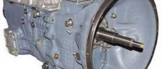
In any car, the gearbox is one of the main units. And if we are talking about KamAZ, then it is also a complex device. This material will help you understand the design features, as well as how to change gears on a KamAZ and what not to do.
Gallery "Transmission Diagrams"
Rules for shifting gearboxes in different conditions
What operating errors can lead to gearbox failure?
Video “Consequences of improper use of the KAMAZ gearbox”
Comments and Reviews
KAMAZ gearbox device
The gearboxes that KAMAZ vehicles are equipped with are fundamentally no different from similar units of other tractors. However, they are not interchangeable and have certain design features.
The most common two variants of the KAMAZ gearbox are the 14th (141, 142, 144) and 15th (152, 154) models.
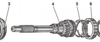
Three shafts are installed in the crankcase of both boxes:
Like any modern manual transmission, they are equipped with synchronizers and have a gear transmission. Reverse gears are installed in a separate block. The speed change mechanism is located in a separate block, which is located in the upper part of the box.
KAMAZ gearbox divider device
A divider is a mechanism that reduces the gear ratio of a gearbox.
Its design includes the following components:
- synchronizer blocking rings installed on both sides;
- a clutch with teeth that synchronizes the rotation of elements;
- two gears;
- two shafts;
- frame;
- gear shift fork;
- lever arm;
- fork roller.
To reduce wear and increase service life, parts operate in an oil environment.
If you are planning to independently repair a KAMAZ gearbox with a divider, the device diagram should be well studied and be at hand.
Kamaz gearbox: device, divider, switching diagram
For a car, the gear shift mechanism is a device, without which operation is unthinkable. If in passenger vehicles the transmission is not considered a simple unit, then in heavy equipment due to its size and weight, things are much worse. Therefore, the KamAZ gearbox is a structurally complex device that requires skills and abilities when handling and maintaining.
Most foreign manufacturers install automatic transmissions on heavy equipment. The creators of KamAZ, in order to simplify the design and increase the reliability of the product, followed the path of a mechanical device. The KamAZ gearbox diagram increases the effect of using the vehicle. Simplicity and convenience make the unit cost-effective.
KAMAZ gearbox diagram with divider
| 1 | Nut M12x1.25-6N | 28 | Spring washer 8 |
| 2 | Lock washer 12.3 | 29 | Gear divider housing hatch cover |
| 3 | Front intermediate shaft bearing cover | 30 | Crankcase stud M16x1.5x22x45 |
| 4 | Lock washer 10 | 31 | Spring washer 16 |
| 5 | Bolt M10x1.25-6gx30 | 32 | Nut M16x1.5-6N |
| 6 | Input shaft bearing cover assembly | 33 | Gear divider synchronizer assembly |
| 7 | Input shaft cover gasket | 34 | Gear divider housing gasket |
| 8 | Adjusting gasket | 35 | Gear divider intermediate shaft assembly |
| 9 | Adjusting gasket | 36 | Intermediate shaft rear bearing seat |
| 10 | Gear divider primary shaft assembly | 37 | Screw M6-6gx16 |
| 11 | Special nut M52x2-L-6N | 38 | Roller bearing |
| 12 | Primary shaft oil injection ring | 39 | Upper clutch housing cover |
| 13 | Pin 4x12 | 40 | Gear divider intermediate shaft |
| 14 | Radial roller bearing with long cylindrical rollers, double row, without rings | 41 | Intermediate shaft gear |
| 15 | Retaining ring | 42 | Gear divider with control assembly |
| 16 | Single row radial ball bearing GOST 520-89 | 43 | Pin 12x35 |
| 17 | Gear divider primary shaft | 44 | Hairpin M16x1.5x22x35 |
| 18 | Prismatic key 6x8x13 | 45 | Single row radial ball bearing with a groove on the outer ring |
| 19 | Primary shaft rear bearing bushing | 46 | Front bearing thrust ring |
| 20 | Gear divider input shaft gear assembly | 47 | Thrust washer |
| 21 | Drain plug with magnet assembly | 48 | Hairpin M12x1.25x18x30 |
| 22 | Gear divider housing with bushings assembly | 49 | Locking bar |
| 23 | Oiler KG/8″ 45 (45916751064) | 50 | Bolt M12x1.25-6gx30 |
| 24 | Eye bolt | 51 | Front intermediate shaft bearing cover gasket |
| 25 | Plug 28 | 52 | Bearing cap sealing ring |
| 26 | Pad | 53 | Lower clutch inspection hatch cover |
| 27 | Bolt M8-6gх16 | 54 | Clutch housing cover |
Purpose, design and operation of the gear divider. Gearbox control with divider
The gear divider ensures smooth alignment of peripheral speeds and shock-free engagement of high and low gears (Fig. 16).
The gear divider is mechanical, accelerating with a pneumatic drive for engaging low and high gears.
Rice. 16. Gear divider (SLIDE No. 31)
The divider consists of a housing cast integrally with the clutch housing, a primary shaft with a gear, synchronizer and bearings, an intermediate shaft with a gear and bearing and a gear shift mechanism (Fig. 17).
| Rice. 17. Gear divider device: (SLIDE No. 32) 1 - adjusting shims; 2 — primary shaft; 3 — oil injection ring; 4 - ball bearing; 5 — rear cover of the input shaft bearing; 6 — hatch cover; 7 — divider synchronizer assembly; 8 — input shaft gear; 9 — bearings of the input shaft gear; 10 — intermediate shaft gear; 11 — intermediate shaft; 12 — bearing; 13 — fork roller; 14 - fork; 15 - fork cracker; 16 — fork lever. |
The primary shaft is mounted on two ball bearings.
The front bearing of the input shaft with a stuffing box is installed in the bore of the engine flywheel, the rear bearing is installed in the socket of the divider crankcase partition.
The axial forces generated during operation of the divider are absorbed by the rear bearing of the divider input shaft.
When the force is directed towards the clutch, the force from the front end of the gear is transmitted to the washer and then to the inner ring of the bearing, through the balls, the outer ring of the bearing - to the cover and through the bolts of its fastening - to the gear divider housing. When the force is directed towards the input shaft of the gearbox, the force is transmitted by the rear end of the gear to the end of the gear coupling of the shaft and then through the shaft, fastening nut, oil injection ring - to the inner ring of the bearing and through the balls, outer ring of the bearing, retaining ring of the bearing - to the gear divider housing .
For forced lubrication of the front bearing of the input shaft of the gearbox and the gear bearings of the secondary shaft of the gearbox, a special oil injection device , which is an oil injection ring.
The required oil level in the divider housing is maintained by communicating with each other through two holes in the walls of the divider housings and the main gearbox.
To ensure smooth alignment of peripheral speeds and shock-free engagement of the high and low gears of the divider, an inertial-type synchronizer with conical friction rings is installed on the input shaft. The divider synchronizer does not differ in operating principle from the main gearbox synchronizers, but is structurally designed differently; the friction rings, springs and retainer balls are unified with the fourth and fifth gear synchronizer.
The divider synchronizer (Fig. 18) consists of a carriage, two identical friction rings, six locking pins and six locking pins.
Rice. 18. Gear divider synchronizer: (SLIDE No. 33)
1 — friction ring; 2 — locking pin; 3 — blocking finger;
4 — synchronizer carriage; 5 — clamp spring; 6 - ball
The synchronizer carriage has a groove on the outer diameter into which the gear shift fork nuts fit. The internal hole of the carriage is slotted, consisting of three toothed rims. The extreme gear rims have a smaller tooth thickness than the middle one, which, when changing gears in conjunction with the gear rims of the primary shaft of the divider, protects the divider from self-switching off while the car is moving, forming a so-called “lock”.
The operation of the divider synchronizer is as follows. (SLIDE No. 34)
When, for example, third gear is engaged, the synchronizer carriage tends to move to the left under the action of the gear shift fork. When the cone of the friction ring comes into contact with the cone of the third gear gear, under the influence of friction forces, the gear drags along the friction ring with the locking pins, turning them relative to the carriage. The chamfers of the carriage holes rest against the chamfers of the locking pins and further movement of the carriage until the peripheral speeds are completely equalized.
When the force of inertia and the moment of friction disappear, the locking fingers will take an indifferent position relative to the holes in the carriage and the carriage will be able to move in the axial direction under the action of the gear shift fork. In this case, the clamp balls are recessed and the carriage moves along the large diameters of the locking pins towards third gear. The carriage ring gear silently meshes with the third gear ring gear.
The intermediate shaft of the divider 11 (see Fig. 17) is mounted on a spherical roller bearing 12, placed in the socket of the divider crankcase partition. The rear support of shaft 11 is the smooth surface of the intermediate shaft of the main gearbox.
The intermediate shafts of the divider and the main gearbox are coaxial and connected to each other using splines.
Gear 10 of the drive of the intermediate shaft of the divider is helical, pressed all the way into the end of shaft 11.
A spherical roller bearing 12 is pressed onto the front journal of shaft 11 until it stops against the shaft collar. From axial movements on the shaft, bearing 12 is secured with a thrust washer screwed to shaft 11 with two bolts.
The outer ring of the bearing, placed in the bearing shell, is held against axial movements by the collar of the shell. An O-ring is installed in the groove of the glass, and a sealing gasket is installed between the end of the glass and the partition. The bearing is covered with a cover.
Axial forces are perceived by the spherical roller bearing 12. When the force is directed towards the clutch, the force from the end of the gear 10 is transmitted to the inner ring of the bearing 12 and then through the rollers, the outer ring of the bearing to the end of the cover and through its fastening bolts to the crankcase.
When the force is directed towards the intermediate shaft of the gearbox, the force from the end of the gear 10 is transmitted to the divider shaft 11 and then through the shaft 11, the thrust washer to the inner ring of the bearing 12 and through the rollers, the outer ring of the bearing, and the bearing cup to the crankcase.
The gear shift mechanism of the divider is designed to ensure that the required gear is engaged while the vehicle is moving and consists of a fork 14 (see Fig. 17) with nuts 15, a roller 13 of the fork 14, at the end of which a lever 16 is installed, and a pneumatic cylinder with a gear shift mechanism housing.
The roller 13 of the fork 14 is installed in the holes of the crankcase. In the middle part, a fork 14 with crackers 15 is installed on the roller 13 on a segment key. The fork 14 is secured with two coupling bolts. To ensure installation and access to the switching mechanism, there is a hatch on the divider housing, closed with a lid. At the outer end of the roller 13, a lever 16 is installed on a segment key, connected to the piston of the power cylinder. Lever 16 is secured with a coupling bolt.
Lever 16 is installed in the upper part of the housing 1 of the gear shift mechanism (Fig. 19). Housing 1 is cast from aluminum alloy, installed on the left side of the divider housing and attached to it with five studs. In the lower part of the body, on one axis, there is a large hole bored for a pneumatic cylinder, in which a piston 7 with a rod is installed, and a small one for installing a piston rod 7.
The piston rod 7 has grooves into which the lever of the gear shift shaft of the divider, located in the upper part of the housing 1, fits. The bore of the housing for the pneumatic cylinder is closed by a cover 8. In the lower part of the housing there are channels for supplying air into the cavity of the pneumatic cylinder from the air distributor 1. At the ends The upper part of the gear shift mechanism housing has installation bolts 6 screwed in on both sides.
Rice. 19. Divider gear shift mechanism with air distributor: (SLIDE No. 35)
1 — air distributor housing; 2 — air distributor spool; 3 - cylinder; 4 - piston; 5 — housing of the divider gear shift mechanism; 6 — installation bolt; 7 — piston with rod; 8 - cover; 9 — breather; 10 - sealing gasket
The divider control valve is designed to supply air to one of the cavities of the air distributor, depending on the gear being engaged. It is installed at the end of the engine cylinder block and consists of a housing 5 (Fig. 21) with a cover 3 and a spool 1 with sockets. The spool seats are pressed into housing 5, and then spool 1 is installed. Spool 1 has two bands with sealing rings and an internal axial hole. There are three holes in the side part of the housing 5 and the spool seats: a central (inlet) for supplying air from the pneumatic system and two for supplying air to the cavities of the air distributor.
Rice. 20. Pneumatic divider control drive: (SLIDE No. 36)
1 - pressure reducing valve; 2 — valve for switching on the divider; 3 — tap switch; 4 — divider control valve; 5 - pneumatic cylinder; 6 – air distributor
In the lower part of the housing 5 there is a hole closed by a filter to release air into the atmosphere. Spool 1 in the housing can occupy two positions. When spool 1 is in the upper position (low gear in the divider), air flows from the inlet through the underwater hole into the rear cavity of the air distributor 6 (see Fig. 20). The front cavity of the air distributor 6 is connected to the atmosphere through the outlet hole in the valve body 4.
When the spool is located at the bottom (highest gear), air enters the front cavity of the air distributor 6, and the rear cavity of the air distributor 6 is connected through a radial hole and an axial channel in the spool and an outlet hole in the valve body 4 with the atmosphere.
Rice. 21. Gear divider control valve: (SLIDE No. 37)
1 - valve cable with spool; 2 - bolt; 3 — valve body cover; 4 — sealing gasket; 5 — valve body; 6 — connecting nut
The divider activation valve 2 (see Fig. 20) is designed to supply air through the pressure reducing valve 1 and the air distributor 6 to the pneumatic cylinder 5 when the driver presses the clutch pedal. The valve is installed on the front panel in the vehicle cabin. The force from the clutch pedal is transmitted to valve 10 through pusher 11. The design of the activation valve is similar to the control valve for the auxiliary brake system, and its design is described below.
Pressure reducing valve 9 is designed to prevent overloading of synchronizer parts when changing gears by limiting the pressure in the pneumatic cylinder to 3.95-4.45 kgf/cm2. It is installed on the left side of the splitter housing.
The pressure reducing valve (Fig. 22) consists of a body 6 with a cover 10, an inlet valve 4 with a spring 2, an inlet valve rod 5 and a membrane 8 with a spring 11.
Rice. 22. Reducing valve: (SLIDE No. 38)
1 - spring housing; 2 — intake valve spring; 3 - gasket; 4 — inlet valve; 5 — intake valve stem; 6 — body; 7 — union nut; 8 - membrane; 9 — washer; 10 — housing cover; 11 — balancing spring; 12 – plug
When the air pressure is less than 4.45 kgf/cm2, the membrane 8, sandwiched between the body 6 and the cover 10, under the action of the spring 11, acts through the rod 5 on the inlet valve 4, moves it to the left and, compressing the spring 2 of the valve 4, lifts it from the seat, made in housing 6. Air freely passes from switching valve 2 (see Fig. 20-3.29) through the open inlet valve to air distributor 6. At the same time, air through the channel in housing 6 (see Fig. 22-3.31) enters the cavity under the membrane 8.
When the pressure at the inlet to the pressure reducing valve increases above 4.45 kgf/cm2, the air, overcoming the force of the spring 11 of the membrane 8, moves it to the right. As a result, the impact from the membrane 8 on the rod 5 of the intake valve 4 is reduced, which, under the influence of the spring 2, also moves to the right and sits on the seat, thereby blocking the air supply to the air distributor.
From the pressure reducing valve, compressed air is supplied to the spool cavity of the air distributor.
The air distributor is designed to supply cavity air into one of the cavities of the pneumatic cylinder, depending on the gear being engaged.
Rice. 23. Air distributor: (SLIDE No. 39)
1 - body; 2 - spool; 3 - piston; 4 - cylinder; 5 - spool seat
The air distributor consists (Fig. 23) of a housing 1 with a spool 2 and two 4 cylinders with pistons 3. The spool housings 5 are pressed into the housing, and then the spool 2 is installed. The spool has two belts with sealing rings. In the lower part of the housing 1 and the spool seats 5 there is an inlet hole for supplying air from the pressure reducing valve, and in the upper part there are two channels for supplying air to the cavities of the pneumatic cylinder. Spool 2 in housing 1 can occupy two positions.
When spool 2 is in the left position, air flows from the inlet through the left channel into the front cavity of the pneumatic cylinder. When the spool is positioned to the right, air enters the rear cavity of the pneumatic cylinder. To control the position of spool 2, it has elongated ends on both sides, which rest against pneumatic pistons 3. Pistons 3 are installed in cylinders 4, fixed to the ends of the housing. The above-piston cavities of the cylinders are connected by pipelines to the divider control valve.
Shifting the gears in the splitter doubles the number of gears, produces ratios that are close to the average of two adjacent gears in the main five-speed transmission, and changes the speed and thrust of the vehicle by a factor of approximately 1.22. (SLIDE No. 40)
Each position of the gear shift lever of the main box corresponds to gears depending on the position of the divider control valve switch. So, with the same position of the gear shift lever of the main box, the upper position of the divider control valve switch corresponds to a gearbox gear that is fast in speed but has lower traction; lower position of the tap switch - lower speed, but higher traction gearbox.
Correct and skillful use of the divider gears by the driver allows you to increase the average speed of the vehicle, reduce the frequency of using the shift lever of the main gearbox, reduce fuel consumption and ensure optimal engine operation.
Gear shifting in gearboxes is carried out: (SLIDE No. 41)
— in the main box — by moving the gear shift lever;
— in the divider — by moving the control valve switch mounted on the gear shift lever. The upper position of the switch corresponds to the highest gear in the divider. The lower position of the switch corresponds to the lowest (direct) gear in the divider.
Gearbox control with divider. (SLIDE No. 42, 43)
Gear shifting in the divider is carried out as follows:
1. Move the divider control valve switch to the extreme position corresponding to the highest or lowest gear.
2. Press the clutch pedal all the way and hold it until the gear in the divider is fully engaged (approximately 1.0 s).
3. Smoothly release the clutch pedal.
Moving the control valve switch to the selected gear position can be done in advance. After this, at the right moment, it is enough to press the clutch pedal all the way to switch to the selected gear (Fig. 24).
Rice. 24. Diagrams of gear shift lever positions for Kamaz and Ural vehicles (SLIDE No. 44)
When starting from a stop, the gear in the divider is selected depending on the road conditions and vehicle load.
It is enough to accelerate a car to a speed of 30-40 km/h only by changing gears in the main gearbox, without changing gears in the divider.
Acceleration at speeds greater than 40 km/h is advisable to carry out using both gears of the divider.
Gear shifting during acceleration , which requires simultaneous gear shifting in the main box and in the divider, in the case of driving in “high gear” in the divider, is carried out in the following sequence:
— move the divider control valve switch to the lower position (“low gear”);
— depress the clutch pedal and engage the next, higher gear in the main gearbox;
— Smoothly release the clutch pedal.
Gear shifting with increasing road resistance , which requires simultaneous gear shifting in the main box and in the divider, in the case of driving in a “low gear” in the divider, is carried out in the following sequence:
— move the divider control valve switch to the upper position (“high gear”);
— depress the clutch pedal and engage the next, lower gear in the main gearbox;
— Smoothly release the clutch pedal.
Repair of KAMAZ gearbox divider
Repair work includes four stages:
- disassembling the unit;
- defective parts;
- replacement of worn elements;
- gearbox assembly.
To repair a gearbox with a divider, you need to perform the following operations:
- remove the air switch;
- unfasten and unscrew the fastening bolts;
- remove the roller;
- remove the gear shift fork;
- remove the synchronizer;
- dismantle the shaft and fork of the release mechanism;
- unscrew the fasteners holding the rear bearing cover on the input shaft;
- remove the cover;
- dismantle the rear bearing and shaft (to do this you will have to align the teeth on the drive gear and shaft);
- remove the bearing cover using the threaded holes made in the intermediate shaft;
- unscrew and unlock the fastening elements;
- remove the support roller washer;
- unscrew the bolts of the cup covering the roller bearing;
- remove the roller bearing and cup from the driven shaft;
- Using a wooden block, knock out the shaft and remove the bearing from the divider housing.
Important: Do not knock out the shaft with a hammer. This will damage the part and will have to be replaced.
- clamp the splined part of the input shaft in a vice;
- unscrew the coupling nut;
- remove the oil injection nut from the shaft;
- Remove the roller bearing, bushing and drive gear.
Next, you need to check and replace worn parts, and then assemble the divider. To assemble, you need to do the operations in reverse order.
Before installing the divider on the machine, you need to make sure that it is assembled correctly and the shafts rotate freely.
The last stage of repair is a test drive. It allows you to check the performance of the divider in real operation. This helps to identify faults that could not be eliminated during repairs.
Source
Gearbox with divider. Device and repair
A gearbox with a divider on a Kamaz vehicle is used to increase gears. Due to the fact that the divider and gearbox have a common lubrication system, when repairing the gearbox it is necessary to ensure that the mechanisms and parts of the divider are in good working order, in addition to the fact that it itself fails,
Divider faults
The main malfunctions of the divider include the following: very often the ball bearings of the driven and drive shafts fall apart. Overdrive gear roller bearings. Rollers break the surfaces of the shaft and gear, leaving characteristic dents on them. The gear teeth break off and the fastening bolts of the driven shaft support washer loosen.
When repairing a gearbox, it is imperative to disassemble the divider. Because there will definitely be hidden defects in the divider.
Disassembling the divider
Let's disassemble the gearbox divider. First of all, remove the gear shift fork. To do this, remove the air switch, unscrew the two fork mounting bolts, having previously unfastened them, and remove the shaft. We remove the synchronizer. Then the fork presses the release bearing together with the shaft. Unscrew the rear input shaft bearing cover. Then the input shaft assembly with the bearing, the cutout of the drive gear must be aligned with the teeth of the intermediate shaft. So that when removing the gears they do not cling to each other. Remove the intermediate shaft ball bearing cover.
Using the threaded holes provided in the cover for removal. We unfasten the two bolts and unscrew them, removing the support washer of the driven shaft bearing, then we proceed to remove the roller bearing of the driven shaft, to do this we dismantle the cup in which the bearing is located, unscrew the fastening bolts, and use the threaded holes provided for dismantling the cup. The bearing comes out along with the glass. After this, using a wooden block, we knock the shaft out of the ball bearing and knock the bearing out of the divider housing.
Differences between multipliers and dividers
Many drivers call both devices a divider, which is not entirely correct from a technical point of view. Both additions to the gearbox exactly double the total number of gears, but this is achieved in different ways. The divider is a two-stage gearbox installed in front of the gearbox, with the first stage allowing the force generated by the engine to be transmitted directly, and the second with an increase in the gear ratio. That is, by activating the divider and engaging fourth gear, you will move at a higher speed than usual, but less than in fifth.
With a range multiplier, the opposite is true: it is installed at the rear of the gearbox and its lower stage allows you to lower the gear ratio of each gear. That is, by turning on the same fourth speed, you will move at an intermediate speed between the third and fourth speeds. Of course, in this case your car will become a little more torquey than in pure fourth gear.
There are vehicles for which speed gradation is extremely important, and in such cases they can be equipped with a range multiplier and a divider at the same time. The total number of gears is obtained not by sequential doubling (4x2x2), but separately with subsequent summation (4x2 + 4x2), that is, not 16, but 12. In other words, using both a divider and a demultiplier at the same time will not work: either one or the other . If the design of the transmission provides for simultaneous operation, then the total number of gears will actually become 16.
Design and principle of operation
Let's consider the location and design of the KamAZ vehicle gearbox. KamAZ trucks are equipped with manual transmissions. They have 5 speeds. The gearbox is switched by pressing the clutch pedals and moving the gearshift lever to the desired position. Since the car is heavy, it is necessary to transfer the gearbox from one gear to another in several stages.
The principle of operation of the KamAZ gearbox is as follows: with a diesel engine it works either in high mode B or in low mode H. They were created to reduce the load on the engine of a heavy vehicle when it is full, and at the same time not force it to work too actively without load.
The design of a KamAZ gearbox with a divider is simple, but it differs depending on the model of the gearbox. Let's look at the KamAZ gearbox diagram, which is found on diesel vehicles. When driving on a flat road, you need to change gears without a clutch. The design of the KamAZ transfer case can be represented by the following formula: 1B - 2B - 3B - 4H - 4B - 5H - 5B.
Switching speeds is carried out as follows:
- First, switch the gearbox operating mode from high to low using a lever.
- Then release the clutch.
- The lever is set to the desired gear, without jumping over them, but turning everything on in order.
There are gearboxes with automatic mode switching.
How does the divider work on KamAZ?
The gearbox divider or multiplier is an additionally installed overdrive, which converts a 5-speed gearbox into a 10-speed gearbox.
The principle of its operation is as follows. The multiplier reduces the ranges between the main gears, tightening the number of gear ratios of the box and expanding them by 20-25 percent.
This modification allows you to improve such vehicle characteristics as:
- fuel efficiency;
- acceleration speed;
- traction force;
- controllability.
The mechanism is located in front of the gearbox, or slightly to the right of it, since the main unit does not experience heavy loads and does not require structural modifications. This allows you to repair and adjust the divider yourself if a malfunction occurs.
Location and order of gear shifting on KamAZ
Most cars from the Kama plant are equipped with manual gearboxes with 5 steps (with or without a divider). Gear shifting is carried out by moving the gearbox rocker with the clutch pedal pressed. But gears on trucks should not be engaged directly, but in stages. Theoretically, this reduces the load on the engine when driving with a full load, and when working with an empty body, it saves fuel.
The usual operating modes of the KamAZ gearbox are increased “B” or decreased “H”. In cars equipped with a gearbox with a multiplier, switching from mode “B” to mode “H” is carried out by lowering a special single divider lever.
What is a demultiplier, its location
First, let's try to figure out what a gearbox range control is, in what cases it is needed and where it is installed.
The multiplier, which is sometimes called a reduction gearbox, is an additional box unit that allows you to get double the number of gears. Its task is to create intermediate driving modes with half the intermediate increase in power, which, if used correctly and in a timely manner, allows you to extend the service life of the entire transmission. Timely use should be understood as driving under load, when none of the available gears provides the optimal driving mode.
Simply put, the multiplier reduces the load on the gearbox gears, doubling the total number of gears.
This additional transmission unit is located behind the gearbox, occupying, in principle, little space and at the same time allowing for increased traction of the vehicle when engaging any direct transmission.
Let's explain this with a specific example. Let's say your car is heavily loaded and you are driving on a section with a very gentle and long incline. The fourth speed is unacceptable for you, since the car simply does not pull, and this mode of operation for the power unit is fraught with many troubles. At third speed, everything seems to be fine, there is enough traction, but you are forced to move at a lower speed than you could, since an increase in speed would lead to a sharp increase in fuel consumption. But if there was one more gear between third and fourth, this would allow the vehicle to move in an optimal mode for the power unit and transmission. That's what a range multiplier is for: it offers such an opportunity. The device is usually turned on using a button located on the gearshift lever. Note that the possibility of doubling speeds can be realized either by increasing or decreasing the gear ratio. Devices of the first type are called demultipliers, the second - dividers. In principle, their tasks are similar, but the implementation mechanism is different.
Specifications
The KamAZ gearbox with a divider includes the following elements:
- a crankcase in which the drive, driven and intermediate shafts assembled with gears are mounted;
- bearings;
- synchronizers,
- reverse gear block,
- top cover of the box,
- gear shift mechanism.
The gearbox of KamAZ vehicles can be five- or ten-speed. The gearbox divider has high and low gears and, in combination with the main gearbox, allows for 10 forward gears and 2 reverse gears. The divider system improves the traction qualities of the machine, makes it easier to control, and reduces the frequency of shifting gears with a lever. Transmission ratios are available in the operating instructions for the device.
The 141 KamAZ gearbox has a reversing light switch. To prevent the simultaneous activation of 2 gears, there is a ball-type lock in the cover, and a spring-finger fuse is used to prevent accidental engagement of reverse gear. The gearbox with divider weighs 320 kg. The cuffs are located in the shaft covers. They protect the gearbox from clogging and prevent oil leakage. Insufficient oil volume in the gearbox leads to its damage. When you first fill the gearbox there should be 9 liters of oil, when changing the fluid - 8 liters.
Technical characteristics of the KamAZ-141 gearbox: Carter:
- The diameter of the bearing bore is 150 mm.
- The diameter of the hole in the gear block axis is 32 mm.
- The diameter of the front bearing journal is 24 mm.
- Rear bearing - 59 mm.
The secondary shaft has the following diameters for the parts:
- Fourth gear gear bushings - 63 mm.
- Roller bearings - 80 mm.
- Reverse gear bushings - 70 mm.
- The outer diameter of the sleeve is 72 mm.
- The diameter of the front bearing journal is 65 mm, the rear one is 49 mm.
- The diameter of the rear bearing cup is 119 mm.
- The diameter of the intermediate shaft is 65 mm.
- The inner diameter of the gear is 65 mm.
The weight of the gearbox with divider is 320 kg.
Gearbox control
Shift gears in the gearbox using the gear lever located to the right of the driver's seat. Change gears with the clutch disengaged. Press the clutch pedal all the way. Engage and shift gears at minimum idle speed. Start driving only from first gear (to avoid premature clutch failure). To quickly accelerate the vehicle on good roads and in difficult conditions, it is recommended to use all gears sequentially according to gear shift patterns. In cars with a cable drive to control the gear shift mechanism, a gearbox with a servo shift is used. The servoshift serves to facilitate gear shifting; air is supplied to it from the car's pneumatic system.
Attention! Do not change gears until the operating pressure in the pneumatic drive is reached (from 6.5 to 8.0 kgf/cm 2 ) to avoid cable breakage due to the servo shift not developing the required force.
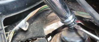
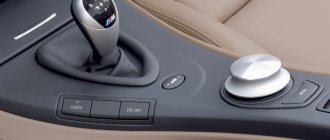
If there is a divider in the gearbox, a gear divider control switch is mounted in the gear shift lever handle (see Fig. Gear shift lever). The switch can be used to select the highest “B” or lowest “H” gear in the divider. It is recommended to use the entire range of low and high gears. To switch from a higher gear to a lower one, and vice versa (without shifting the lever), you need to move the gear divider control switch to the desired position, and then press and release the clutch pedal after a short (1 second) delay - the gear will engage automatically. To simultaneously shift the lever and engage a higher or lower gear, set the divider control switch to the “B” or “H” position, press the clutch pedal and shift the lever.
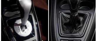
Gear shift lever
For gearboxes of models 144, 154, shift gears according to the diagrams (see Fig. Gear shift diagram in a model 144 gearbox and Gear shift diagram in a model 154 gearbox).
Shift diagram for a 144 transmission
Shift diagram for a 154 transmission
For the ZF 9S1310 model gearbox, shift gears according to the diagram (see Fig. Gear shift diagram in the ZF 9S1310 model gearbox):
- 1-2-3-4-lower gears (lowest range of multiplier);
- 5-6-7-8-high gears (highest range of range).
When slowing down, change gears only sequentially: 8-7-6-5-4-3-2-1. Always keep the gear engaged when driving.
Gear shift diagram in the gearbox model ZF 9S1310
Low gear “C” is intended for starting in difficult road conditions and for maneuvering.
Attention! For gearboxes it is strictly prohibited:
- switch from the highest range of the multiplier to the lower range of the multiplier at a speed of more than 30 km/h (for ZF gearboxes);
- move with the gear shift lever in neutral position;
- engage reverse gear (R) when the vehicle is not completely stopped and when the clutch plate is rotating.
Gear shifting in the multiplier occurs automatically: the highest gear is engaged when the gearbox control lever moves from the fourth to the fifth position, the lowest gear is engaged when switching from fifth to fourth. When the lever is moved through the “◊” position, the valve is activated, providing automatic switching of the range multiplier. When the low range is turned on in the range multiplier, the warning lamp lights up on the instrument panel
. When the range shifter is switched, the gear shift lever rod of the main box is blocked, and a force is felt on the lever, after which it is recommended to wait 1-1.5 seconds to ensure the gear shift in the range shifter.
How to change gears on KamAZ
To change gears correctly, you need to know how the transmission works. The gearbox is designed in such a way that movement is often carried out at a reduced speed, so the machine can transport heavy loads. KamAZ has a 5-speed gearbox. You need to change gears using the clutch pedal and lever.
Start of movement
Before you start moving, you must press the reduced speed. Shift gears only with the clutch pedal depressed. The gear shift pattern is based on staged gear shifting. To start driving a truck, you need to spin the crankshaft of the internal combustion engine.
The second gear must be engaged when the needle on the tachometer reaches mark 3, which means 3000 rpm. This method of gear shifting will make it possible to extend the life of the gearbox and reduce gasoline consumption.
Switching speeds
Let's consider the procedure for switching gears after the car has already started moving. When KamAZ accelerates, the gear shift order is: 4H - 4B - 5H. To engage speed 2, the crankshaft speed must increase to 3000 rpm according to the tachometer readings. The functions of the crankshaft are basic.
Reverse
To engage reverse on a truck, you need to place the switch in the lower left position. Reverse gear cannot be engaged while the vehicle is moving. To engage reverse, you must first completely stop the unit, then perform a maneuver.
How much does a box cost for KamAZ?
You can buy a gearbox for KamAZ in a specialized store, where they will show you a price list with the available models. The purchase price of a gearbox depends on the model of truck on which it will be installed. So the cost of a KamAZ gearbox ranges from 55,000 to 153,000 rubles. The price of the gearbox for KamAZ 141 is 62,000 rubles. The highest prices for KamAZ gearboxes of Euro-3 environmental class.
The transfer case is controlled by a pneumatic valve, the handle of which is located on an additional panel under the instrument panel (see Fig. Transfer case gear shift valve handle).
Transfer case shift valve handle
The gear shift valve handle has three fixed positions, each of which corresponds to a transfer case gear: N – neutral. Bridges are disabled. I - the handle is turned to the right, the first (low) gear is engaged. At the same time, the downshift indicator light on the instrument panel lights up. Engage the first (lowest) gear before driving along difficult sections of the road, as well as when parking the car for long periods. II – the handle is turned to the left – the second (highest) gear is engaged. Engage the second (highest) gear before driving on paved roads.
Attention! You can change gears only after the car has come to a complete stop and with the gear shift lever in the neutral position in the gearbox. Engaging neutral in the transfer case while the engine is running and the gear in the gearbox is engaged is prohibited.
If the pneumatic system fails, it is possible to force a gear shift in the transfer case (see section 7 “Possible malfunctions of vehicle units and systems. Self-help”).
The transfer case center differential lock is controlled pneumatically by a handle located on an additional panel under the instrument panel. The lock should be turned on immediately before overcoming difficult sections of the route (sticky soil, obstacles, slippery muddy roads).
Attention! Activation of the transfer case center differential is allowed only after the vehicle has come to a complete stop and with the gear shift lever in the gearbox in neutral position. The transfer case center differential lock must be disabled immediately when driving onto a hard, dry road, since driving with the lock engaged on a hard road can lead to damage to the transfer case parts.
Handle for controlling the locking of the center differential of the transfer case
The tap handle has two fixed positions:
- locking enabled - right position 1;
- locking is off - left position 2.
When the lock is turned on, the indicator lamp for turning on the center differential lock of the transfer case lights up on the instrument panel and lights up while the differential is locked. If the control lamp does not light up, you must:
- turn off the lock by setting the center differential lock control valve handle to position 2;
- carefully move the car forward 0.5-1 meter. If there is no traction, turn the drive wheels;
- turn on the locking by setting the tap handle to position 1. Then move away smoothly, without jerking, to reduce wear on the teeth of the locking clutch.
Attention! Driving a vehicle with the transfer case center differential lock engaged is only allowed when the warning light is on.
Switching rules under different conditions
Gear changes depend on the various conditions in which the vehicle is moving. These rules should be followed so that during the use of the gearbox it does not fail.
Climb
During an ascent, you must switch the gearbox to mode H, as a result of which the transmission will begin to operate at increased voltage.
The following rules must be followed:
- When switching from 1st to 2nd gear when ascending a KamAZ truck, you must use the method of depressing the clutch pedal twice.
- In order for the crankshaft to work correctly when changing gears, you need to use the fuel pedal; it also needs to be pressed periodically. At the same time, you can overcome any steepest climb.
- The shaft speed when lifting must be more than 2000 rpm. Otherwise, the engine may shut down, which may cause an accident while driving on the road.
- During the climb, switch to the desired mode, this will facilitate the operation of the engine and all components of the machine.
Descent
Some drivers turn off the engine when descending a mountain to save gas. This should not be allowed at KamAZ.
If you turn off the internal combustion engine during a trip, the electric booster will not perform its functions, which will lead to the steering wheel locking.
KamAZ braking occurs not only as a result of stopping the engine, but also by activating the auxiliary braking system. When a heavy vehicle is going downhill and the driver applies the auxiliary brakes, the clutch should not be depressed and the driver should not shift from one gear to another.
Icy areas
You need to drive a truck on icy areas with maximum speed and range. When braking, you must use the engine stop assist system. If emergency braking is required, the operator must stop the trailer wheels. If you do not take this rule into account, you may end up in a skid.
It is possible to slow down the internal combustion engine only as an exception, as this can lead to its wear. When braking, the wheels should not slip. To avoid this, you need to turn off the reduced speed, which will help reduce the rotation of the crankshaft.
Skid
When skidding, do not disengage the clutch. When the truck skids, you need to turn the steering wheel in the direction of the skid. If the KamAZ skids, you need to take your foot off the gas pedal and press the differential. This must be done using the regulator located on the panel. As a result, the indicator on the panel will turn on. You need to start the move from the second high gear. After overcoming the skid, the differential should be unlocked.
Overdrive device
The overdrive gear used in divider-type gearboxes allows you to select gentle driving modes and is used mainly for long trips at high speeds (in relation to trucks, of course). In addition to saving fuel, which in such cases can be significant, the use of a divider makes it possible to reduce the noise level during operation of the engine-transmission combination, reducing the load and wear of the power unit.
When the divider is turned on, the propeller shaft begins to rotate at a higher speed than the engine crankshaft. The divider doubles the number of gears on the vehicle, both forward and reverse. But if the machine has other gearboxes (for example, reduction gearboxes), their simultaneous use will be impossible.
Switching features in different models
On KamAZ vehicles of various models and configurations (tractor tractors - 44108 or 5490; dump trucks - 6520 or 55111; trucks - 5320, or military model 5350; road trains - 5410, 65206) the following gearboxes are installed:
- 141, 142 and 144 – mechanical gearboxes, 5-speed (used in light trucks, and are similar in design and operating principle to passenger car gearboxes);
- 152 and 154 – mechanical gearboxes with a multiplier, ten-speed;
- German-made ZF-6S1000 gearbox with mechanical shifting, 6-speed with a full set of synchronizers;
- ZF-9S109 and ZF-9S1310 – mechanical 9-speed gearboxes with a range shifter.
Malfunctions and repairs
Transmission repair consists of disassembling the unit, diagnosing, repairing or replacing worn elements. After the mechanism is restored, the unit is reassembled and the system is tested in operation. You can contact a service center, but it is better to repair the transfer case yourself.
How to check the oil level
The oil level in the box is checked as follows. Unscrew the crankcase plug. When checking, you must install the crankcase indicator into the hole until it stops. The oil from the crankcase of a ten-speed manual transmission is drained through 3 holes. Of these, 2 holes are located in the lower part of the gearbox housing, and the third is located in the divider. The five-speed gearbox housing is drained through 2 holes.
Change of oil
To change the oil, you need to wash the gearbox housing with engine oil. Clean the magnetic plugs from metal particles and fill in oil to the top line of the indicator. The oil level is measured after 5 minutes. When the car is moving, the gearbox should operate without hesitation, speeds should be switched freely and locked firmly. Loud noise may indicate worn shaft bearings, insufficient oil level, or poor quality lubricant in the crankcase.
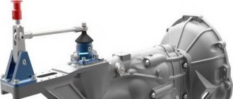
How to remove the box
Removing the gearbox is carried out as follows:
- You need to remove the driveshaft. To do this, unscrew the 4 fastening nuts.
- The PSU is being removed.
- Dismantle the starter mountings.
- Disconnect the tube that goes to the reduction gear.
- Remove the gear shift lever.
- Place a jack between the flywheel and the engine pan, and dismantle the engine through a wooden stand.
- Unscrew the rear yoke nuts and remove it.
- Dismantle the spacer rod.
- Unscrew the exhaust system bracket fastening bolts.
- Connect the hoist to the bolts and tighten it.
- Unscrew the fastening nuts to the side engine mounts.
- Unscrew the bolts that secure the gearbox to the internal combustion engine.
- Raise the hoist and move the gearbox away from the engine to the output of the transmission input shaft.
- Pull out the gearbox.
How to adjust
Now you need to adjust the gearbox and troubleshoot components and parts. If they fail, replace them with new ones. Spline connections must not have defects or chips. Gear bearings should be replaced after first inspecting the place where they are installed to see if there is any wear or areas pressed through by the rollers.
The shaft bearings are replaced because, as a result of breakage and metal shavings getting into the oil, the rolling areas of the bearings were damaged, which could cause gearbox failure. Inspect the gears, detect damage and wear of gear teeth. The conical synchronizer races must not be deformed or worn. The guide shafts should not be loose. There should be no damage to the splines.
How to assemble correctly
The gearbox is assembled in the reverse order. The intermediate shaft is installed in the gearbox housing. Mount the bearings - front roller and rear spherical. Tighten the support washer. Fix it with a nut and close the rear cover of the spherical bearing mount. Install gaskets. The shaft should rotate easily, there should be no jamming of the part when moving.
Repair diagram for KamAZ-5320 gearbox with divider
To repair the KAMAZ-152 gearbox with a divider, it must be disassembled. Analysis includes the following steps:
- To disassemble the box, you will first need to dismantle the air switch and unscrew the fasteners;
- remove the gearbox shift shaft and fork;
- the next step will be to dismantle the fork and release shaft, as well as the synchronizer;
- Next, you need to open the rear bearing cover by unscrewing the screws that first fix it;
- dismantle the bearing and shaft;
- also, to open access to the gearbox multiplier, you will need to remove the support roller washer, metal cup and driven shaft bearing;
- using a rubber (not metal) hammer or a wooden block, you must carefully remove the bearing from the multiplier housing, being careful not to crush the part;
- next you need to remove the coupling and oil injection nuts using the appropriate wrenches;
- The last stage of disassembling the unit is to dismantle the roller bearing, bushing, and gearbox drive gear.
Next, you should inspect all the parts and replace worn ones, and then assemble the device, following the above instructions in reverse order.