The Oka car (modifications 1111, 11113) is a small car of the first group of the especially small class. Almost all components and mechanisms of the car were borrowed from other proven VAZ models.
The transmission is no exception, since the Oka gearbox essentially resembles the VAZ-2108 transmission, adapted to the engine of this car (size, certain design features, operating parameters).
Oka gearbox: main parameters
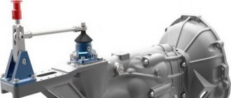
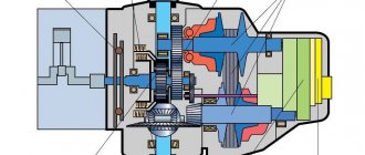
The basic transmission on the Oka is a two-shaft, four-speed manual transmission with a final drive and differential. The transmission of torque from the internal combustion engine to the drive wheels is carried out through two drive shafts with hinges.
The Oka gearbox and the device diagram using the example of the VAZ-1111 Oka involves a number of components. The Oka checkpoint housing consists of the following elements:
- clutch housing;
- gearbox housing;
- lid.
This box consists of more than 20 parts, the main ones include:
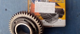
- gears;
- bearings;
- synchronizers;
- oil seals;
- seals;
- sump;
- clamps, etc.;
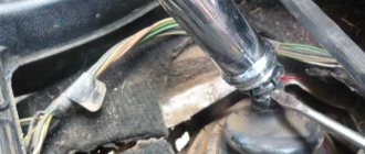
As mentioned above, the Oka gearbox has a remote control; the design includes a gear shift drive, consisting of the following parts:
- floor shift lever;
- ball joint and rod;
- backstage;
- hinges;
- gear selection rod and gear selection mechanisms.
The main causes of Oka gearbox malfunctions and frequent breakdowns
The mechanical box of the Eye has a large number of parts, each of which can break. Like any mechanical device, the transmission is not immune to breakdowns. The main causes of Oka gearbox malfunctions include:
- Extraneous noise when shifting the gear shift lever to the neutral position (poor quality lubricant or lack thereof, wear of the input shaft bearings, shaft displacement, etc.). The problem is solved by replacing damaged/worn elements;
- Difficult gear shifting (defect of the cardan joint, damage to the rod lever, etc.). The problem is resolved by replacing damaged parts or adjusting them;
- Spontaneous gear disengagement (wear or damage to gears, deformation of control forks, etc.). The malfunction is eliminated by changing the faulty elements of the box, and the mechanism drive is also adjusted.
You can also separately highlight the causes of malfunctions in the drive mechanism of the Oka gearbox. For example, a malfunction in the operation of the gear shift mechanism occurs for the following reasons:
- Shifting gears is difficult or completely absent (deformation or damage to the hinge of the control mechanism mounted on the rod, loosening of the tension clamp). It is necessary to check the condition of the hinge and tighten the fasteners on it, which usually allows you to restore the functionality of the control mechanism.
- The Oka gear shift lever is not secured well enough (wear of the rocker elements, formation of backlashes in it). The problem is eliminated by troubleshooting or replacing worn elements;
How to remove a gearbox on Oka
On the one hand, there are problems that do not require dismantling the box to eliminate. In this case, there is also a group of malfunctions when the box is removed. The box can be dismantled either independently or at a service station by qualified specialists. There are two types of dismantling:
- removing a gearbox without a vehicle's internal combustion engine (without affecting the vehicle's power plant itself, many elements and assemblies are unscrewed and disconnected);
- removing the gearbox along with the vehicle's internal combustion engine (there is a need to drain the technical fluid and disconnect almost all attachments).
The sequence for dismantling the box without removing the internal combustion engine is as follows:
- install the car on an overpass or inspection hole;
- unscrew the nuts securing the drive shafts in the hub and remove the front wheels;
- disconnect the battery terminal and all wires, as well as cables from the box;
- remove the starter and unscrew the fastenings of the lower shield of the mounting housing and then dismantle it;
- unscrew the drive rods and disconnect the steering mechanism supports from the longitudinal beam;
- remove the cross member and pull the drive limit switches out of the hub;
- Unscrew the fastening of the strut and bracket of the left side of the anti-roll bar;
- disconnect the fasteners of the engine support bracket from the box;
- place a stop under the box and remove the left longitudinal beam of the subframe;
- remove the drive shaft end switches from the box and remove the motor support bracket from it;
- Unscrew all fasteners of the gearbox to the internal combustion engine, then move it towards the left wheel and remove the box.
The sequence of dismantling the box together with the internal combustion engine of the car by lowering the components down:
- drain the working fluid (oil) from the gearbox;
- disconnect all elements from the box and the internal combustion engine (cooling system pipes, wiring, etc.);
- disconnect the column from the steering mechanism and tighten the fasteners of the shock-absorbing strut supports;
- Place a wooden pallet underneath the engine;
- to lower the engine, gearbox, steering gear, front suspension and subframe onto a wooden pallet, unscrew all fasteners of the subframe to the car body;
- dismantle the gearbox by lifting the front of the car and pushing it back;
Let us also add that with the help of a lift, dismantling the box together with the car engine can be done by lifting the components up.
Replacing oil seals
Most often, the drive shaft oil seals located at the installation site of the internal hinge limit switches in the gearbox must be replaced. A sign of wear is indicated by the presence of transmission oil leaks on the inner CV joint and adjacent surfaces of the housing.
Replacing gearbox seals is a relatively simple operation, but requires complete dismantling of the drive shafts.
The work algorithm is as follows:
- We install the car on the pit;
- We tear off and twist the nuts holding the drive in the hub;
- We hang up the front of the car and remove the wheels;
- We disconnect the steering tip and the ball joint from the hub;
- By pulling the hub to the side, we remove the end switch of the outer CV joint from it;
- We climb under the car;
- Using a hammer and a socket, we strike the end of the inner CV joint until the retaining ring installed on the end comes out of the groove;
- Remove the drive shaft assembly;
- Use a screwdriver to pry off the “old oil seal;
- We install a new seal using a mandrel;
- We install the drive in place;
- We assemble the car;
The technology for replacing the seal installed in the gearbox control mechanism is even simpler - disconnect the drive rods, dismantle the hinge and remove the leaking oil seal.
Carter
Carter 1 is cast from aluminum alloy. It contains sockets for bearings 22, 15 and 2 of the primary and secondary shafts and differential, three sockets for gear shift rods 16, 17, 19, perpendicular to which the sockets of the rod clamps are located. Balls 11 (see Chapter 20) with springs 13 are installed in these sockets, which are closed with screw plugs.
There is a drain hole at the bottom of the gearbox housing to release used oil. The drain hole is closed with screw plug 4 (see Chapter 19).
To prevent pressure from being created in the crankcase when the gears rotate and oil splashes, the cavity of the gearbox housing communicates with the atmosphere through breather 37. The breather tube is pressed into the hole in the clutch housing. A rubber cap 36 is placed on top of the tube. To prevent oil from escaping through the breather, the breather cavity is isolated from the gearbox cavity by a plate 31, which is screwed to the clutch housing.
Power plant and transmission on Oka
The VAZ 1111/1113 car can be equipped with a two-cylinder engine. The automotive system has a reaction rod, which is located in the gearbox control drive.
The crankcase of the power plant contains shafts driven by a gear mounted on the crankshaft. The rear crankcase cover is secured with 6 bolts. The crankcase has a magnet, which is necessary to catch metal wear debris.
Depending on the modification, the Oka can be equipped with a mechanical transmission type, which can be designed for 4 or 5 speeds. The VAZ 1113 transmission includes a single-plate dry clutch. This car has a bevel differential. The gearbox is 4-speed, including synchronizers in all forward gears.
The operation of the transmission system affects the quality of acceleration and fuel efficiency. The maximum speed on this version of the domestic car can reach 140 km/h. At the same time, the acceleration of the car to hundreds, depending on the engine size available, varies within 25-30 seconds. Oka can be refilled with AI-92. At the same time, fuel is consumed almost equally in all cycles.
The VAZ 1111/1113 car can be equipped with a two-cylinder engine. The automotive system has a reaction rod, which is located in the gearbox control drive.
Disassembled gearbox
Depending on the modification, the Oka can be equipped with a mechanical transmission type, which can be designed for 4 or 5 speeds. The VAZ 1113 transmission includes a single-plate dry clutch. This car has a bevel differential. The gearbox is 4-speed, including synchronizers in all forward gears.
Back cover
The ball bearings of the primary and secondary shafts are closed by a rear cover 21, in which there is a channel for the oil meter ruler 23. The ruler has marks indicating the maximum and minimum oil levels in the gearbox. The ruler is sealed in the hole of the lid with a rubber stopper.
Outside, in the upper part of the cover, there is a boss in which there is a socket for the rubber bushings of the clutch cable damper.
The reverse intermediate gear 8 (see Chapter 20) is located on a tubular axis 4, the ends of which rest in the holes of the clutch housing and gearbox. The gear wheel rotates on an axis on a bronze bushing. The gear ring of the wheel is spur-cut, with the end beveled at a slight angle for better engagement of the gears when engaging reverse.
The gear wheel has an annular groove for the reverse fork 7. To prevent the reverse gear from switching off automatically under load, the teeth on all reverse gears are made with reverse taper in the direction of the tooth. When reverse gear is engaged, the intermediate gear 8 connects the gear 54 of the input shaft with the ring gear of the clutch 53 for the synchronizer of 1st and 2nd gears. At the same time, the reverse fork presses on the control lamp switch rod, and the lamp circuit is closed.
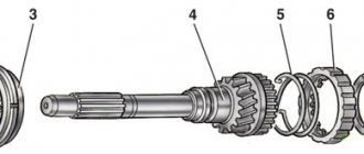
The main gear consists of a pair of helical spur gears. The drive gear is made together with the secondary shaft, the driven gear 42 (see figure) is made in the form of a crown, which is bolted to the flange of the differential box 43.
The differential is conical with two satellites 51 installed on an axle 53, which is held in the differential box by retaining rings 52. Grooves are cut on the landing belts of the axle to improve the lubrication conditions for the contacting surfaces of the satellites and the axle.
The gear wheels of the axle shafts 46 rest with their ends on bronze washers 44, the selection of the thickness of which regulates the axial movement of each gear; it should be no more than 0.1 mm. Each gear wheel of the axle shaft is mounted on the spokes of the wheel drive joint housing 49 and is held on it by a retaining ring 45. At the exit from the clutch and gearbox housings, the housings of the internal joints (half shafts) are sealed with seals 5.
The differential box rotates in two tapered roller bearings 2, the preload in which is adjusted by selecting the thickness of the adjusting ring 3. A plastic drive gear 47 of the speedometer drive is pressed onto the differential box.
The driven gear wheel of the speedometer drive with its shaft rests on two metal-ceramic bushings: one is pressed into the clutch housing, the second into the speedometer drive housing.
At the exit from the housing, the gear shaft is sealed with a cuff. The speedometer drive assembly 50 is attached to the clutch housing using a nut and a pin, sealed with a rubber ring and sealed. The cable fastening nut 48 is screwed onto the speedometer drive housing.
To catch wear particles, a permanent magnet is installed at the bottom of the gearbox housing.
When designing the VAZ Oka modifications 1111 and 11113, the designers used many solutions tested on other VAZ models. This applies to almost all components and mechanisms of the car, including the transmission.
The designers “ripped off” the Oka checkpoint from the VAZ-2108, one of the main “donors” for the small car. The designers, in fact, took the box from the Eight and adapted it to the Oka engine. Therefore, the VAZ-2108 and Oka gearboxes are almost identical in general design; the main difference comes down to dimensions, certain design features and operating parameters.
Disassembly, troubleshooting and assembly of the VAZ “OKA” 1111 1988-2008 gearbox
- Repair manuals
- VAZ "OKA" 1111 1988-2008
- Disassembly, troubleshooting and assembly of the gearbox
You will need: keys “10”, “13” and “22”, a screwdriver, a hammer, pliers for removing the retaining rings.
| 1. Remove the gearbox from the vehicle (see “Removing and installing the gearbox”) and drain the oil from it, if this has not been done in advance. |
| NOTE If you are replacing the clutch housing, remove the bearing and clutch release fork (see “Replacing the clutch release bearing” and “Replacing the clutch release fork”), and also press out the oil seals of the input shaft and axle shafts. |
| WARNING If at least one of the following parts is replaced during transmission repair: clutch housing or gearbox housing, differential housing or differential bearings, then it is necessary to select a differential bearing adjusting ring (see “Selecting a differential bearing adjusting ring”). |
| 2. Insert a screwdriver between the reflector and the hinge body and, hitting it with a hammer, knock out the shank of the internal wheel drive joint from the gearbox. | 3. Remove the oil slinger. In the same way, disconnect the second drive from the gearbox. |
| 4. Remove the oil level indicator from the gearbox housing. | 5. Remove the reverse light switch from the housing. |
| NOTE Please note: There is an aluminum O-ring underneath the switch. |
| 6. Remove the six bolts securing the rear transmission cover. |
| NOTE Please note that there is a spring washer installed under the head of each bolt. |
| 7. Using a screwdriver, separate the rear cover from the gearbox housing. |
| 8. Carefully remove the rear cover gasket. |
| 9. Remove the snap ring from the output shaft rear bearing. | 10. In the same way, remove the retaining ring from the rear bearing of the input shaft. |
| 11. Unscrew the three plugs of the clamps. | 12. Carefully, so as not to lose the retainer springs, remove the plugs. |
| 13. Remove the retainer springs. |
| 14. Carefully tilt the gearbox and remove the retainer balls. | 15. Remove eleven bolts and unscrew the nut securing the gearbox and clutch housings. |
| NOTE Please note that there is a spring washer under each bolt head and nut. |
| 16. Remove the ring located under one of the bolts. | 17. To separate the gearbox and clutch housings, insert a screwdriver into three slots in turn (the third slot is on the other side of the gearbox) and separate the gearbox housing from the clutch housing. |
| 18. Remove the transmission housing from the clutch housing. |
| 19. Carefully remove the sealing gasket. |
| 20. Remove the bolt securing the 1st and 2nd gear shift fork. |
| NOTE Please note that the forks are attached with special bolts. |
| 21. Remove the 1st and 2nd gear shift rod. | 22. Remove the 1st and 2nd gear shift fork. |
| 23. Remove the bolt securing the 3rd and 4th gear shift fork. | 24. Rotate the 3rd and 4th gear shift rod to disengage the rod guide from the gear selector lever. |
| 25. Remove the rod and fork. | 26. Remove the locking block from the rod hole. |
| 27. Remove the reverse idler gear shaft. | 28. Remove the reverse intermediate gear. |
| 29. Using a slight rocking motion, remove the input and output shafts at the same time. | 30. Remove the differential from the clutch housing. |
| 31. Remove the reverse gear shift rod and... | 32. ...move its lead out of the hole in the reverse gear fork. |
| 33. Remove the four bolts securing the gear selection mechanism (spring washers are installed under the bolts). | 34. Remove the gear selection mechanism. |
| 35. Remove two plungers from the holes of the mechanism. | 36. Remove the two screws securing the protective plate and remove the protective plate |
| NOTE Please note that there is a spring washer installed under the head of each screw. |
| 37. Remove the bolt securing the speedometer drive housing and remove the speedometer drive assembly with the driven gear. |
| NOTE Please note that there is a spring washer installed under the bolt head. |
| 38. Remove the magnet from the clutch housing. | 39. If it is necessary to remove the gear selector rod, use a screwdriver to pry the edge of the rod protective cover and slide it off the rod support sleeve... |
| 40. ...unscrew lever 1 from the gear selector rod (it is fixed with special TB1324 glue) and remove rod 2 from the clutch housing. | 41. If it is necessary to replace the rod hinge, slide the protective cover off it and unscrew the hinge mounting bolt (it is fixed with special TB1324 glue). |
| 42. If necessary, press out the front bearing of the secondary shaft. To do this, place metal plates of suitable size and... | 43. ... using a wrench, press the bearing out of the crankcase, being careful not to damage the oil sump. |
| 44. Remove the oil sump; if damaged, replace it. | 45. Press in the bearing using a suitable mandrel, applying force only to the outer ring of the bearing (remember to install the oil pan first). |
| 46. To press out the input shaft bearing, make a hook from stiff wire. Insert the hook into one of the two grooves in the crankcase and slide it under the bearing. Then… | 47. ...using a screwdriver (placing a wooden block) press the bearing out of the crankcase, applying force to the opposite end of the screwdriver with hammer blows and alternately moving the hook in the grooves. |
| 48. Inspect the clutch housings and gearboxes. There should be no cracks or chips on them. There should be no nicks, scratches, dents, etc. on the mating surfaces. Remove minor damage with sandpaper. If the defect cannot be eliminated, replace the part. |
| 49. Check the bearing seats in the clutch housing and gearbox housing. These surfaces must show no signs of wear or damage. Otherwise, replace the crankcases. |
| 50. Wash and blow out the breather hole with compressed air. |
| 51. Inspect the back cover. There should be no cracks or chips on it. There should be no nicks, scratches, dents, etc. on the mating surface. |
| 52. Check the condition of the ball bearings. If the raceways, cage or balls are damaged, or if play is detected in the bearing (the radial play in it should not exceed 0.05 mm), replace the bearing. |
| 53. Check the condition of the gear shift rods. Replace bent rods, or rods with burrs, burrs, or worn out retainer holes. Replace the forks if they are bent or their tabs are worn. |
| 54. Check: the rods should slide freely in the holes of the crankcase and gear selection mechanism. |
| 55. Check the condition of the axle shaft seals. They must be without warping or tears. Working edge 1 should be smooth, without tears, dents or rubber sagging, and spring 2 should be intact and unstretched. Replace defective seals (see “Replacing gearbox seals”). |
| 56. Check (replace if necessary) the input shaft oil seal and... | 57. ...gear selector rod oil seal (see “Replacing gearbox oil seals”). |
| 58. Check the reliability of gear engagement and ease of movement of the synchronizer clutches. Otherwise, repair or replace the synchronizers. | 59. Clean the magnet from particles of wear parts. Replace the magnet if it is cracked or if its magnetic properties are weakened. |
| 60. Replace torn or badly compressed crankcase and rear cover gaskets. |
| USEFUL TIPS It is recommended to replace the gaskets regardless of their condition. |
| 61. Assemble the gearbox in the reverse order of disassembly, having first cleaned the mating surfaces of the crankcases from the remnants of the old gasket. Please take into account the following features of the assembly process. |
| 62. When installing the locking device plungers, generously lubricate the process hole with grease. | 63. Insert the plunger into the hole and... |
| 64. ...push it into place between the far and middle holes for the rods (hold the plunger from below with your finger as it passes through the holes in the rods). | 65. Also install the second plunger between the middle and near holes for the rods. |
| 66. When installing the gear selector, make sure that the head of the gear selector lever fits into the socket of the gear selector rod lever. Pre-lubricate the lever head with grease. | 67. When installing the reverse gear intermediate gear, install it with a groove on the reverse gear fork and... |
| 68. ...turn 90°, making sure that the fork remains in the gear groove. |
| NOTE Pay attention to how the forks should be installed on the gear shift rods: 1 – rod with the 3rd and 4th gear shift fork, 2 – rod with the 1st and 2nd gear shift fork, 3 – reverse gear shift rod progress. |
| 69. When installing the 3rd and 4th gear shift rod, do not forget to insert a blocking block into its hole. | 70. Before installing the shafts, engage the teeth of their gears and install them in the clutch housing in this position. |
| 71. Don't forget to reinstall the magnet. | 72. For ease of installation, “glue” the gasket to the clutch housing with grease. |
| 73. Liberally lubricate all rubbing parts with transmission oil. |
| 74. When connecting the clutch housings and gearbox, install long bolts in through holes. Install an eye under the bolt indicated by the arrow. |
| 75. Tighten and lock the shaft bearing nuts if the shafts have been disassembled. After final assembly of the gearbox, check the gear engagement by moving the gear selector rod. |
↓ Comments ↓
VAZ-1111-11113 OKA
Section 1. VEHICLE STRUCTURE
General information about cars Vehicle registration data
Section 2. ENGINE
Possible engine malfunctions, their causes and solutions Useful tips Replacing the coolant Replacing the engine oil and oil filter Cleaning the crankcase ventilation system Setting the piston of the first cylinder to the TDC position of the compression stroke Adjusting the tension of the camshaft drive belt Replacing the tension roller Replacing the camshaft drive belt Removing, installation and troubleshooting of the flywheel Replacement of engine seal parts Cylinder head Adjustment of clearances in the valve drive Removal and installation of the engine Engine repair Lubrication system Cooling system Exhaust system Power supply system
Section 3. TRANSMISSION
Clutch Gearbox Front wheel drives
Section 4. CHASSIS
Front suspension Rear suspension
Section 5. STEERING
Inspection and check of the steering system on the vehicle Steering column Steering mechanism Steering linkage
Section 6.BRAKE SYSTEM
Checking and adjusting the brake system Replacing the brake fluid Bleeding the brake system hydraulic drive Master cylinder Brake vacuum booster Pressure regulator Replacing brake hydraulic hoses and pipelines Front wheel brakes Rear wheel brakes Parking brake
Section 7. ELECTRICAL EQUIPMENT
Fuses and relays Generator Starter Ignition system Lighting, light and sound alarms Windshield wipers and washers Engine cooling fan Instrument cluster Switches and switches
Section 8.BODY
Possible body malfunctions, their causes and solutions Replacement of buffers Hood Side door Rear door Rear view mirrors Seats Heater Body care
Applications
Appendix 1. Tightening torques for threaded connections Appendix 2. Fuels and lubricants and operating fluids Appendix 3. Basic data for adjustments and control Appendix 4. Filling volumes, l Appendix 5. Oil seals Appendix 6. Layout of rolling bearings Appendix 7. Car electrical diagram : 1 — side turn signal repeater; 2 — front direction indicator; 3 - headlight; 4 — electric motor of the cooling system fan; 5 — sound signal; 6 - sensor for turning on the electric motor
Gearbox failures
When is gearbox repair required? The owner of the vehicle must check the box if the following signs appear:
- difficult gear shifting;
- spontaneous activation of gears;
- noises from the box;
- There is an oil leak.
In some cases, transmission breakdowns on a car can be caused mechanically. In particular, the clutch housing can break if, during a trip, the car collides with an external obstacle, for example, a curb. Also, a problem with the clutch housing may be a result of wear on the secondary shaft. Movement will be complicated if the crankcase has cracks.
It is necessary to repair the gear shift lever if it begins to move with difficulty. In this case, installing a new ball joint or spring, as well as a spherical washer, can help. If the lever is worn, it is worth replacing it.
Carrying out repairs yourself is a real task.
In some cases, transmission breakdowns on a car can be caused mechanically. In particular, the clutch housing can break if, during a trip, the car collides with an external obstacle, for example, a curb. Also, a problem with the clutch housing may be a result of wear on the secondary shaft. Movement will be complicated if the crankcase has cracks.
Primary shaft
The input shaft 39 of the gearbox is made in the form of a block of drive gears, rotating in two bearings. Roller bearing 32 is pressed into the clutch housing 35, ball bearing 22 is pressed into the gearbox housing. It secures the input shaft from axial displacement and is secured to the shaft with a nut, and in the crankcase socket with an adjusting ring 20. The nut is caulked after tightening. The bearing mounting ring is pressed against the crankcase wall by the rear cover.
At the exit from the clutch housing, the input shaft is sealed with seal 33, the working edge of which is pressed against the polished belt of the shaft. The shaft passes through the guide sleeve of the clutch 38, which is attached with its flange to the clutch housing with three bolts. The gear block includes drive gears of 1st, 2nd, 3rd, 4th gears and reverse gears. The reverse gear, unlike other gears, is spur-cut.
Transmission repair needed
What tools are required when surveying a checkpoint on the Oka?
To begin repair and restoration work, you need to remove the speed box. However, it is recommended to drain the oil before doing this. When disassembling the gearbox, you need to unscrew the rear crankcase cover, retaining rings, and retainer plugs. The next step is to disconnect the gearbox housing from the clutch housing.
You can use a screwdriver specifically for this. The gear shift fork mounting bolt must be unscrewed. The rod is removed along with the plug. Next, you need to remove the locking pin, then dismantle the shafts, remove the plungers, and the differential. The subject to be photographed is the magnet that is present in the clutch housing. Finally, the gear selection mechanism is removed.
The Oka has a special gear selection mechanism, which includes:
- frame;
- reverse gear fork;
- springs;
- lever arm.
In order to repair this mechanism, it is necessary to dismantle the speed box. Next, during disassembly of the gearbox, the device itself is removed. When reassembling the gear selection mechanism, you should pay attention to the springs; there are two of them (upper and lower). One of them is galvanized, the other is not. The non-galvanized spring is the top one. In addition, they differ in elasticity.
The occurrence of grinding noise can be eliminated by adjusting the clutch. There are several reasons why noise occurs. One of them is that the gear oil has lost its working properties. Also, a low fuel level may cause extraneous noise.
If spontaneous gear disengagement occurs, the driver of the car must check the condition of the clutch housing. However, there are many reasons why gears suddenly switch off, ranging from the presence of worn bushings to deformation of the lever fork.
To begin repair and restoration work, you need to remove the speed box. However, it is recommended to drain the oil before doing this. When disassembling the gearbox, you need to unscrew the rear crankcase cover, retaining rings, and retainer plugs. The next step is to disconnect the gearbox housing from the clutch housing.
You can use a screwdriver specifically for this. The gear shift fork mounting bolt must be unscrewed. The rod is removed along with the plug. Next, you need to remove the locking pin, then dismantle the shafts, remove the plungers, and the differential. The subject to be photographed is the magnet that is present in the clutch housing. Finally, the gear selection mechanism is removed.
Transmission repair (Video)
VAZ cars (KAMAZ, SeAZ)-1111, 11113.
This operation is performed when the clutch does not fully engage or disengage (slips or drives) and the defect cannot be eliminated by adjustments. We have written in detail about signs of wear or clutch malfunction more than once, for example, in magazine No. 9 for 1995 and in No. 12 for 1996.
To dismantle the clutch on the Oka, no special tool is required. A set of wrenches, sockets with extensions and universal joint are required, as well as a mandrel to center the clutch disc on the flywheel during assembly. Attention! The repair manual says that you can use a “Zhiguli” mandrel, but this is not true. “Oka” needs its own, special one. We selected a tall head from the tool kit for this purpose. In general, you can even plan a mandrel from a piece of wood.
It is better to carry out work on a ditch or a lift together with an assistant. We start with operations under the hood of the car.
Disconnect the negative wire from the battery and the connector with wires from the spark torque sensor.
Secondary shaft
The secondary shaft 18 is manufactured together with the eye drive gear. Four belts are machined on the surface of the shaft to accommodate gears, and slots are cut in two places for attaching synchronizer hubs. To reduce friction losses and increase the efficiency of the gearbox, the gears on the secondary shaft are mounted on needle bearings 25 of the same size with a solid plastic cage.
The secondary shaft is stepped, which made it possible to maintain optimal gaps between the teeth of the gear wheels. In order to ensure the assembly of synchronizers and gears on the shaft with this shaft shape, the size of the needle bearings is selected according to the shaft flange of the largest diameter. Therefore, the remaining bearings are located on bushings of the same size as the shaft collar for gear 7 of the first gear.
A thrust ring 10 is installed between the needle bearings and the gears of the 2nd and 3rd gears, and a thrust washer is installed between the drive gear of the main gear and the 1st gear gear.
To improve lubrication of needle bearings, an axial channel and radial holes are drilled in the secondary shaft, and internal annular grooves are machined in the bearing bushings, coinciding with the radial holes of the shaft, as well as radial holes in the bearing area. The oil sump shank 41 is installed from the end of the secondary shaft into the axial channel.
When the shaft rotates, oil is sprayed by the gears and, through the guide channel in the clutch housing, enters the oil chamber behind the front bearing 40 of the secondary shaft and then through the oil sump 41 into the axial channel of the shaft and, due to centrifugal forces, is thrown out through the radial holes to the gear bearings.
The secondary shaft rotates in roller bearing 40 and ball bearing 15. The latter is pressed into the gearbox housing, and a thrust washer 14 is installed between it and the bushing of the fourth gear gear bearing. Ball bearing 15 is fixed in the housing housing and on the shaft in the same way as ball bearing 22 of the primary shaft , installation ring 20. Roller bearing 40 is pressed into the clutch housing along with the oil sump.
The gear wheels of the secondary shaft are designed in the same way and differ from each other in size. Each wheel has two rims: a helical one for engagement with the drive gear of the input shaft and a spur gear for the synchronizer. In front of the synchronizer rim, a conical belt is made on the gear wheel, on which the synchronizer locking ring 26 is located.
What does the Oka clutch consist of?
Let's start from the pedal and go to the very end. Firstly, a cable drive is installed on the Oka. It has several advantages. For example, low cost, ease of maintenance, ease of replacement, durability. Secondly, the clutch unit itself is double-disc, as on most modern cars. Multi-disc types are usually installed on motorcycles.
The master and slave disks are the basis of the block. The drive (basket) is screwed onto a flywheel mounted on the engine crankshaft. But the driven one is installed on the input shaft of the gearbox using only a splined connection. Another part of the assembly is the release bearing, which is necessary to press the driven disk away from the drive disk. The bearing moves along the input shaft and rotates freely.
Synchronizer
The synchronizer ensures shockless gear engagement. It consists of a hub 12, a coupling 28, crackers 29, springs and two blocking rings 26. The synchronizer hub is seated on the spokes of the secondary shaft and is clamped: for the synchronizer of the 3rd and 4th gears between the needle bearing bushings, for the synchronizer of the 1st and 2nd gears - between the needle bearing bushing bearing and the shoulder of the secondary shaft.
The hub has six grooves, three of which have holes drilled for the retainer springs. In these grooves there are crackers 29 with retaining balls. Splines are cut along the outer diameter of the hub 12, along which the sliding clutch 28 of the synchronizer can move. It has sockets inside for the balls of the clamps, and outside there is an annular groove for the gear shift fork 27.
On both sides of the coupling there are bronze blocking rings 26, each having six projections that fit into the grooves of the hub. In this case, three short protrusions go into the grooves in which the clamps are located, and longer and wider ones go into other grooves. These projections are installed in grooves with a side clearance equal to half the thickness of the coupling (hub) tooth.
When choosing this gap, the angle of rotation of the blocking ring relative to the hub is limited. With this connection, the hub rotates together with the locking rings. The conical part of the blocking rings is located on the conical belts of the secondary shaft gears. When the gear is engaged, these conical surfaces come into contact.
To increase friction forces, threads are cut on the contact surfaces of the rings and longitudinal grooves are made. As a result, the oil film breaks at the point of contact and increases the friction properties of the conical surfaces. The locking ring has a toothed ring, the teeth of which are beveled at a certain angle. A sliding clutch is connected to the gear ring of the blocking ring when the gear is engaged.
The sliding clutch 28 has an internal crown with which it is located on the teeth of the hub. The ends of the coupling teeth are beveled at the same angle as the teeth of the blocking rings and synchronizer rims. To prevent gears from switching off automatically under load, the teeth of the gear synchronizer ring are made conical, and the teeth of the sliding clutch have undercuts.
Main settings
The VAZ “Oka” 1111 and 11113 gearbox is a two-shaft, 4-speed gearbox, combined with a main gear and a differential. All forward gears are synchronized. The transmission of rotation to the front drive wheels from the gearbox is carried out by means of two drive shafts with joints of equal angular velocities. The weight of the unit is only 24.5 kg.
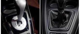
Due to the transverse location of the power plant, the gearbox is controlled remotely.
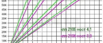
| Gear ratios "Oka" 1111 and 11113 | ||
| broadcast | 1111 | 11113 |
| 1st | 3,7 | |
| 2nd | 2,06 | |
| 3rd | 1,27 | |
| 4th | 0,9 | |
| back | 3,67 | |
| home | 4,54 | 4,1 |
The design of the gearbox is quite well developed, which ensures quite acceptable driving performance of the Oka.
The dismantling of the box from the car is carried out in case of certain breakdowns and the need for repairs.
The main types of breakdowns include:
- Breakdown or damage to the housing;
- Damage or wear of gears, synchronizers;
- Bearing wear;
- Bending of the forks of the control mechanism;
The gearbox will also have to be removed if the clutch components are replaced - discs (driver, driven), release bearing or its fork.
Transmission malfunctions appear quite clearly in the form of:
- Increased noise level;
- The appearance of grinding, crunching and other third-party sounds;
- Inability to engage any gear;
- Spontaneous transmission shutdown;
Other malfunctions of the unit include wear of the seals and malfunction of the drive. But these problems do not require removing the gearbox from the car, with the exception of wear on the input shaft seal (it can only be reached from the clutch housing and for this the box must be removed from the car).
Major breakdowns
The simple design of the clutch on the Oka and a small number of components ensures reliability of the unit, but its service life depends on the operating conditions of the vehicle. If you work carefully with the clutch, the unit can last a long time.
There are not so many malfunctions that can occur with the clutch on the Oka:
- Wear or destruction of friction linings;
- Damage to dampers, driven disk hub;
- Destruction of the release spring;
- Release bearing wear;
- Gust, “fluffing” of the cable;
There are other types of faults, but they are very rare.
Driven disk
The most common reason for the need for clutch repair is critical wear of the friction linings of the driven disc. Such a breakdown is accompanied by the appearance of third-party sounds when using the clutch (especially when starting to move), jerking, and “slipping.” Theoretically, to restore the functionality of the clutch, it is enough to replace the clutches on the disk, but this operation is now impractical, so the worn part is simply replaced with a new one.
At the first signs of critical wear on the driven disk, it is better to immediately replace it, since further use of the car can lead to damage to the working surface of the drive disk, and then it will have to be replaced as well.
Other failures of the driven disk include damage to the dampers (needed to smooth out jerks during the start of rotation transmission), which leads to twitching of the car when starting from a standstill. Also, over time, the splines on the disk hub, with the help of which it “sits” on the shaft, can wear out. These malfunctions are relatively rare, and they can be eliminated by replacing the driven disk.
Spring, bearing
The diaphragm release spring is an element included in the design of the basket. It is made of spring steel and rarely breaks. But if its “petals” burst, the operation of the clutch is disrupted - when the spring is pressed, the drive disk is retracted with a skew, which is accompanied by uneven wear of the clutches and “driving” of the clutch. It is impossible to replace a damaged spring, and clutch repair in this case consists of replacing the basket.
The release bearing is not a highly loaded unit, so it can last quite a long time. But over time, it also wears out, which is accompanied by the appearance of a characteristic “rustle” when the clutch pedal is depressed. This part is not repairable and if it fails, it is simply replaced.
Drive unit
Malfunctions of the cable drive include its tearing and “fluffing” (only a few of its threads break). At the first malfunction, the driver completely loses control of the clutch - the clutch pedal has failed and it will not be possible to disconnect the engine from the gearbox.
Sometimes a situation arises when only a few strands of the cable break. This problem is accompanied by difficult movement of the clutch pedal, its wedging, since the ends of the broken threads cling to the cable braid. All drive malfunctions are resolved by replacing the cable.
Drive failures, backstage repairs
The box includes many components. The full list of parts is as follows:
- Frame;
- Differential bearing;
- Installation spacer;
- Grease drain plug;
- Semi-axial seal;
- Drive shaft (left);
- Gear 1st speed 2nd. shaft;
- Synchronizer clutch for 1st, 2nd speeds, as well as reverse;
- 2nd speed gear sec. shaft;
- Thrust ring;
- 3rd speed gear sec. shaft;
- Synchronizer clutch for 3rd, 4th speeds, as well as reverse;
- 4th speed gear sec. shaft;
- 4th speed gear thrust ring;
- Bearing;
- 1st and 2nd speed fork axle;
- 3rd and 4th speed fork axle;
- Deut. shaft;
- Reverse fork axle;
- Installation ring;
- Lid;
- Bearing;
- Dipstick;
- Gear 4th speed primary. shaft;
- Gear bearing;
- synchronizer ring for 3rd and 4th speeds;
- Fork;
- coupling;
- Rusk;
- Retainer;
- Plate;
- Bearing;
- Stuffing box;
- Release bearing fork;
- Clutch housing;
- Cap;
- Breather;
- Release bearing;
- Perv. shaft;
- Bearing;
- Sump;
- Main drive driven gear;
- Differential housing;
- Washer;
- Retaining ring;
- Axle gear;
- Speedometer drive gear;
- Speedometer cable;
- Drive shaft (right wheel);
- Speedometer drive housing;
- Satellite;
- Retaining ring;
- Axle of satellites;
- Anther;
- Stock;
Since the Oka gearbox has a remote control, its design additionally includes a drive for the gear selection mechanism.
The drive consists of:
- Gearbox lever (installed in the passenger compartment on the central tunnel);
- Backstage;
- 2 rods (reactive and drive lever);
- Hinge;
- A rod connected to the speed selection mechanism;
The multi-component design of the gearbox drive is not very reliable - over time, adjustment of the connections and repair of the rocker is required.
The Oka has problems not only with the gearbox, but also with its drive. The main problems with the drive are the gearshift lever dangling, and it is impossible to turn on any speed.
In the first case, the malfunction lies in the wear of the elements of the link (ball joint). Disassembly, troubleshooting and replacement of worn components allows you to fully restore the functionality of the rocker and eliminate the backlash in it, which is the reason that the lever dangles a lot.
If checking the rocker showed that it is in good condition, you should look and check the hinge mounted on the rod of the control mechanism. The same element can also cause the inability to engage gears. If its tightening clamp is loosened, then the drive rod will rotate in it, but no impact will be transmitted to the control mechanism. Checking the condition of the hinge and tightening the fasteners on it allows you to eliminate problems with the operation of the drive.
General design of the gearbox and its drive
The box includes many components. The full list of parts is as follows:
The components of the unit are lubricated by splashing. Transmission oil is used as a lubricant; the filling volume is 1.8 liters. The amount of oil in the gearbox is checked using a dipstick.
Since the Oka gearbox has a remote control, its design additionally includes a drive for the gear selection mechanism.
The drive consists of:
The multi-component design of the gearbox drive is not very reliable - over time, adjustment of the connections and repair of the rocker is required.
Removing the unit from the car
Thanks to its simple design, repairing the Oka gearbox yourself is quite possible. Most often, problems are caused by removing the transmission from a car, rather than repairing it.
Removing the gearbox from the Oka is possible in two ways - only the gearbox itself is removed, or it is removed together with the power plant, and only then the gearbox is disconnected from the engine and undergoes repair.
Each method has its own specific difficulties. In the first case, you have to disconnect the assembly in quite cramped conditions and require unscrewing and disconnecting many components, but the engine is not affected. If removal is carried out together with the power unit, then technical fluids need to be drained and almost all attachments must be disconnected, but removing the motor and gearbox itself is easier.
Removing the gearbox only
Let's look at the algorithm for removing the gearbox using an example when the engine is not affected:
- We place the car on a viewing hole, overpass, or use a lift;
- We tear off and twist the nuts securing the drive shafts in the hub;
- We hang up the front of the car, remove the front wheels;
- Disconnect the battery terminal;
- We disconnect all wires and cables from the box (“mass” wire, plug of the sensor for turning on the reverse signal light, cables);
- Remove the starter;
- Unscrew the fastening of the lower shield of the clutch housing and remove it;
- Unscrew the drive rods (reaction rod, drive lever);
- We disconnect the steering mechanism supports from the longitudinal beam (after unscrewing the fasteners);
- We dismantle the cross member;
- We pull out the end switches of the drive shafts from the hub;
- We release the left side of the anti-roll bar (to do this, unscrew the fastening of its strut and bracket);
- We disconnect the fasteners of the support bracket of the power unit located on the box;
- We place a support under the gearbox (transmission rack, a massive wooden beam of suitable length);
- Unscrew the fasteners of the left longitudinal beam of the subframe and remove it;
- We remove the end switches of the drive shafts from the gearbox (knock them out using the adapter);
- Remove the motor support bracket from the gearbox;
- We unscrew all the fasteners of the box to the engine;
- We move the box towards the left wheel to remove the limit switch of the input shaft and remove it;
You should remove the box with an assistant, since the fairly massive assembly will have to be held above your head when removing it.
One of the rather interesting methods of dismantling the gearbox along with the engine is the method of lowering the components down. Moreover, this technology allows you to do without even an inspection hole.
The general algorithm of actions is as follows:
- We merge those. liquids;
- We disconnect from the engine and gearbox all the elements that go outside the engine compartment (cooling system pipes, fuel pipes, wiring, cables, drive rods. We also dismantle the cooling system radiator, disconnect the muffler from the exhaust pipe of the exhaust system and unscrew the brake system pipes from front brake mechanisms);
- Disconnect the column from the steering mechanism;
- We twist the fasteners of the shock-absorbing strut supports;
- We place a “pillow” (wooden pallet) under the engine from below;
- We unscrew all the fasteners of the subframe to the body (after which the engine, along with the gearbox, front suspension, steering gear, and subframe will lower onto the “cushion”);
- We lift the front of the car and push it back;
After this, the box is dismantled, disassembled, component troubleshooting, repair and replacement of faulty parts is carried out.
The disadvantage of this method can be considered a certain complexity of reassembly, since it is not possible to correctly “bring” and put the body on the subframe the first time.
VAZ 11113
We remove the gearbox using an inspection pit or a lift.
- Disconnect the negative cable from the battery.
- Drain the oil from the gearbox (see “Changing the oil in the gearbox”).
- Disconnect the clutch cable from the gearbox.
- Disconnect the reverse light switch connector.
- Disconnect the speedometer cable from the drive.
- We knock out the inner hinge of the right drive without disconnecting the drive from the wheel.
- We remove the left drive completely (see “Removing the front wheel drives”).
- We disconnect the gear shift drive rod from the rod joint and the reaction rod from the gearbox, remove the starter and the left support of the power unit.
- Using a 13mm socket, unscrew the left and loosen the right nuts securing the rear cross member of the subframe.
- We move the crossbar back.
- Using a socket and a 13mm wrench, unscrew the nuts of the two bolts securing the removable (left) subframe pipe to the front cross member.
- We take out the bolts
- Using a 13mm socket, unscrew the two nuts securing the left stabilizer bar bracket to the subframe pipe.
- Remove the bracket.
- Using two 17mm spanners, unscrew the nut of the bolt securing the left stabilizer bar strut to the suspension arm.
- We take out the bolt.
- Using two 13mm spanners, unscrew the two nuts of the bolts on the left securing the steering gear bracket to the subframe pipe.
- Using a 19mm socket, unscrew the bolt on the left securing the subframe pipe to the body.
- Remove the subframe pipe assembly with the lever extension and the lever with the ball joint.
- Using a 10mm socket, unscrew the two bolts securing the clutch housing cover to the rear oil seal holder.
- Using a 10mm wrench, unscrew the bolt securing the cover to the clutch housing.
- Remove the cover.
- Using a 13mm wrench, unscrew the nut securing the earth wire to the gearbox.
- We remove the wire.
- Using a 17mm spanner, unscrew the lower bolt of the front fastening of the gearbox to the engine and the lower bolt of the rear fastening, located above the inner hinge of the right-hand drive (the bolt can be finally removed after dismantling the rear support of the power unit).
- Having unscrewed the upper bolt securing the gearbox to the engine with a “17” head, we move it away from the engine, disconnecting the input shaft of the box from the driven clutch disc, and remove the box.
I remove the box on the oka, change the leaking oil seal
in the video I tell you how to remove the box on the oka and replace the input shaft oil seal.
Replacing the gearbox on an OKA car
How to remove the box with minimal effort.
ATTENTION! When removing or installing the gearbox, do not rest the input shaft on the clutch pressure spring leaves to avoid damaging them.
We install the gearbox in the reverse order.
Before installing the box, apply a thin layer of CV joint-4 grease to the splined end of the input shaft and the outer surface of the clutch release (release) bearing guide sleeve.
>Removing the eye box