07/18/2021 9,496 VAZ 2107
Author: Ivan Baranov
A clean windshield is very important for the safety of the driver and passengers. Therefore, if the wipers on a VAZ 2107 do not work, this can lead to an unpleasant situation on the road. The article provides an electrical diagram of the windshield wiper, discusses malfunctions and solutions.
[Hide]
Contacts of steering column switches for VAZ 2105, 2107 cars
On VAZ 2105, 2107 cars there are three steering column switches. Diagram: contacts (pinout) of steering column switches for VAZ 2105, 2107 cars
1.To the right side direction indicators (block X2/5 of the mounting block).
2.To the hazard warning switch.
3.To the relay-breaker for direction indicators and hazard warning lights.
4.To the hazard warning switch.
5. To the left side direction indicators (block X3/5 of the mounting block).
6.To the hazard warning switch.
7. High beam headlights.
8.Low beam headlights.
9. To the exterior lighting switch (+).
10.To the ignition switch (short-term inclusion of high beam headlights).
20.On the washer motor.
Notes and additions
— The contact diagram of the steering column switches for VAZ 2105, 2107 cars of different years of production may differ in the color of the wires.
More articles on electrical equipment of VAZ 2105, 2107 cars
Car diagram - VAZ 2105
Some useful electrical diagrams for the VAZ 2105 1980-1992. VAZ-2105 model in its design almost corresponded to the European fashion of the early 1980s. This allowed the model to be sold in a number of European countries for many years to come. Although in Europe such rear-wheel drive four-door five-seater sedans began to lose ground to front-wheel drive models already in the 70s. Since its appearance (and even more so now), this classic sedan has not become prestigious for many car owners and, accordingly, has not become AvtoVAZ’s most popular product. This did not prevent it from being considered the most progressive design before the advent of front-wheel drive VAZs. Externally, the car received straight lines of body design, large rectangular block headlights at the front and rear, aluminum bumpers, fenders with then fashionable cut contours, and the camshaft was driven by a belt rather than the usual chain. The ventilation system differs from the previous ones by the presence of rectangular deflectors. Heated rear window is standard! The fuse and relay box is located in the engine compartment.
Basic electrical circuit of VAZ-2105
1 – block headlights, 2 – side direction indicators, 3 – battery, 4 – starter activation relay, 5 – electro-pneumatic valve for the carburetor forced idle economizer, 6 – starter, 7 – carburetor microswitch, 8 – generator 37.3701, 9 – headlight cleaners , 10 – sound signals, 11 – spark plugs, 12 – engine compartment lamp, 13 – oil pressure warning lamp sensor, 14 – coolant temperature indicator sensor, 15 – ignition distributor, 16 – brake fluid level sensor, 17 – ignition coil, 18 – windshield wiper, 19 – electric headlight washer motor, 20 – electric windshield washer motor, 21 – control unit for the electro-pneumatic valve of the carburetor forced idle economizer, 22 – ignition switch, 23 – ignition relay, 24 – relay-interrupter for direction indicators and hazard warning lights, 25 – reverse light switch, 26 – brake light switch, 27 – windshield wiper relay, 28 – mounting block, 29 – socket for portable lamp, 30 – glove compartment lighting lamp, 31 – cigarette lighter, 32 – heater fan motor , 33 – parking brake warning lamp switch, 34 – carburetor air damper warning lamp switch, 35 – three-lever switch, 36 – hazard warning switch, 37 – instrument lighting switch, 38 – exterior lighting switch, 39 – lamp switches located in the door pillars , 40 – fog light circuit fuse, 41 – oil pressure warning lamp, 42 – rear fog light switch, 43 – fuel reserve warning lamp, 44 – instrument cluster, 45 – battery charging warning lamp, 46 – parking lamp warning lamp breaker relay brakes, 47 – interior lamps, 48 – parking brake indicator lamp, 49 – carburetor air damper indicator lamp, 50 – indicator lamp unit, 51 – rear fog light indicator lamp, 52 – rear window heating indicator lamp, 53 – level indicator lamp brake fluid, 54 – voltmeter, 55 – side light indicator lamp, 56 – turn signal indicator lamp, 57 – speedometer, 58 – headlight high beam indicator lamp, 59 – heater fan switch, 60 – rear window heating switch, 61 – additional resistor heater electric motor, 62 – plug connector for connecting the bar, 63 – rear lights, 64 – license plate lights, 65 – fuel gauge sensor, 66 – rear window heating element, A – order of conditional numbering of plugs in the wiper pads 9 headlights, relay 27 and windshield wiper 18, carburetor solenoid valve control unit 21, B - the order of conventional numbering of plugs in the blocks of the mounting block and three-lever switch.
Basic electrical diagram of the VAZ-2104
1 – headlights; 2 – side direction indicators; 3 – battery; 4 – starter switch relay; 5 – electro-pneumatic valve of the carburetor forced idle economizer; 6 – starter; 7 – carburetor microswitch; 8 – generator 37.3701; 9 – headlight cleaners; 10 – sound signals; 11 – spark plugs; 12 – engine compartment lamp; 13 – oil pressure warning lamp sensor; 14 – coolant temperature indicator sensor; 15 – ignition distributor; 16 – brake fluid level sensor; 17 – ignition coil; 18 – windshield wiper; 19 – headlight washer motor; 20 – windshield washer electric motor; 21 – control unit for the electro-pneumatic valve of the carburetor forced idle economizer; 22 – ignition switch; 23 – ignition relay; 24 – relay-interrupter for direction indicators and hazard warning lights; 25 – mounting block; 26 – reverse light switch; 27 – brake light switch; 28 – windshield wiper relay; 29 – switch for the carburetor air damper warning lamp; 30 – plug socket for a portable lamp; 31 – glove box lighting lamp; 32 – cigarette lighter; 33 – heater fan electric motor; 34 – additional resistor of the heater electric motor; 35 – rear window heating switch; 36 – parking brake warning lamp switch; 37 – rear window wiper and washer switch; 38 – three-lever switch; 39 – alarm switch; 40 – instrument lighting switch; 41 – external lighting switch; 42 – lamp switches located in the door pillars; 43 – fog light circuit fuse; 44 – oil pressure warning lamp; 45 – rear fog light switch; 46 – fuel reserve warning lamp; 47 – instrument cluster; 48 – battery charging indicator lamp; 49 – interior lamps; 50 – relay-interrupter for the parking brake warning lamp; 51 – parking brake warning lamp; 52 – control lamp for the carburetor air damper; 53 – control lamp block; 54 – rear fog light indicator lamp; 55 – control lamp for heated rear window; 56 – brake fluid level warning lamp; 57 – voltmeter; 58 – side light indicator lamp; 59 – turn signal indicator lamp; 60 – speedometer; 61 – control lamp for high beam headlights; 62 – heater fan switch; 63 – rear lights; 64 – rear window washer electric motor; 65 – rear window wiper; 66 – license plate lights; 67 – courtesy light for the rear part of the cabin; 68 – rear window heating element; 69 – fuel level indicator sensor; A – the order of conventional numbering of plugs in the headlight wiper blocks 9, relay 28 and windshield wiper 18, rear window wiper 65 and carburetor solenoid valve control unit 21; B – the order of conditional numbering of plugs in blocks
Electrical diagram of injection system connections
1 – electric motor of the engine cooling system fan: 2 – mounting block; 3 – idle speed regulator; 4 – electronic control unit; 5 – octane potentiometer; 6 – spark plugs; 7 – ignition module; 8 – crankshaft position sensor; 9 – electric fuel pump with fuel level sensor; 10 – tachometer; 11 – control lamp “CHECK ENGINE”; 12 – car ignition relay; 13 – speed sensor; 14 – diagnostic block; 15 – nozzle; 16 – adsorber purge valve; 17, 18, 19 – injection system fuses; 20 – ignition relay for the injection system; 21 – relay for turning on the electric fuel pump; 22 – intake pipe electric heater relay; 23 – electric heater of the intake pipe; 24 – intake pipe heater fuse; 25 – oxygen concentration sensor; 26 – coolant temperature sensor; 27 – throttle position sensor; 28 – air temperature sensor; 29 – absolute pressure sensor; A – to the “plus” terminal of the battery; B – to terminal “15” of the ignition switch; P4 – fan motor activation relay
Electrical diagram for connecting the instrument cluster
1 – oil pressure warning lamp sensor; 2 – coolant temperature indicator sensor; 3 – mounting block; 4 – ignition relay; 5 – ignition switch; 6 – fuel level indicator sensor; 7 – instrument cluster; A – to terminal “30” of the generator; B – to the instrument lighting switch
Connection of brake system warning lamps - diagram
1 – brake fluid level sensor; 2 – mounting block; 3 – ignition relay; 4 – ignition switch; 5 – brake fluid level warning lamp; 6 – parking brake warning lamp; 7 – relay-interrupter for the parking brake warning lamp; 8 – parking brake warning lamp switch; A – to terminal “30” of the generator
Turning on the headlight cleaners and washers - electrical diagram
1 – gearmotors for headlight cleaners; 2 – electric motor for headlight washer; 3 – mounting block; 4 – ignition switch; 5 – windshield washer switch in the three-lever switch (at the same time it is a headlight washer switch); P2 – relay for turning on the headlight cleaners and washer; A – the order of conditional numbering of plugs in the headlight cleaner blocks; B - to terminal “30” of the generator
Electrical circuit for switching on the heater fan motor
1 – mounting block; 2 – heater motor switch; 3 – additional resistor; 4 – heater electric motor; 5 – ignition switch; A – to terminal “30” of the generator
Circuit diagram for switching on the windshield wiper and washer
1 – thermobimetallic fuse; 2 – windshield wiper gear motor; 3 – windshield washer electric motor; 4 – mounting block; 5 – washer switch in the three-lever switch; 6 – wiper switch in a three-lever switch; 7 – windshield wiper relay; 8 – ignition switch; A – to terminal “30” of the generator; B – the order of conditional numbering of plugs in the blocks of the gearmotor and the wiper relay
Wiring diagram for turning on direction indicators and hazard warning lights on a VAZ 2105
1 – block headlights with front direction indicators; 2 – side direction indicators; 3 – mounting block; 4 – ignition relay; 5 – ignition switch; 6 – relay-interrupter for direction indicators and hazard warning lights; 7 – turn signal indicator lamp located in the speedometer; 8 – rear lights with direction indicator lamps; 9 – alarm switch; 10 – direction indicator switch in a three-lever switch; A – to terminal “30” of the generator; B – numbering of plugs in the hazard warning switch; B – the order of conditional numbering of plugs in the relay-interrupter of direction indicators and hazard warning lights
Schematic diagram of a glass cleaner on a VAZ 2107
- fuse;
- wiper motor;
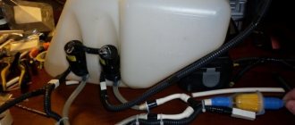
- windshield washer motor;
- relay and fuse box;
- washer switch (water supply to glass);
- three-lever cleaning speed switch;
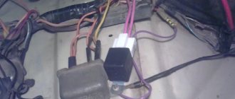
- VAZ 2107 cleaner relay. Type RS-514. Its mounting location is under the dashboard on the left, attached directly to the body;
- egnition lock;
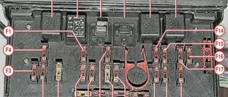
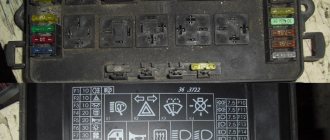
The standard wipers on the VAZ 2107 operate in intermittent and continuous modes. If they do not work at all, then first we do the simplest thing: before starting repairs, we check the fuse and the degree of oxidation of its contacts in the mounting block (location F2 for 10 A). The fuse is shared with the washer pump motor. So if the fuse is at fault, then water will not splash on the glass. When changing a fuse, pay attention to the size and color.
If the wipers do not work in rare rain mode, then most likely the relay in the mounting block or the steering column switch itself is to blame. The diagram shows that if there is power on the wire suitable for the relay and the control light is on, or the ammeter deflects the arrow, then the relay is at fault, adjustment will not help, replacement is needed. If there is no current, then there is an open circuit in the steering wheel, and the switch is to blame.
Why did the wipers stop not at the base of the windshield, but “just anywhere”? The gearbox is to blame for this. What should we do with it?
Replacing the gearbox is an alternative, since due to its design, adjustment and repair are difficult, and spare parts are not sold; repair and replacement of its parts (although the size allows) is not carried out, with the exception of the gearbox gear.
Wiring diagram for the windshield cleaner and washer of the VAZ 2105 Zhiguli
/ VAZ/ vaz-2105/ Electrical diagrams/ Wiring diagram for the windshield wiper and washer
| 1 – thermobimetallic fuse; 2 – windshield wiper gear motor; 3 – windshield washer electric motor; 4 – mounting block; 5 – washer switch in the three-lever switch; | 6 – wiper switch in a three-lever switch; 7 – windshield wiper relay; 8 – ignition switch; A – to terminal “30” of the generator; B – the order of conditional numbering of plugs in the blocks of the gearmotor and the wiper relay |
Repairing auto parts yourself is a responsible task that should be taken as seriously as possible. Sometimes a faulty spare part takes the driver by surprise, forcing him to spend a lot of time and money searching for a good service station, but there is an alternative solution to the problem; this requires a small amount of knowledge and a set of tools.
When repairing the circuit for switching on the windshield wiper and washer of a VAZ 2105 Zhiguli, you need to be extremely careful and not neglect the little things. To get acquainted with the issue, car enthusiasts often use various Internet portals dedicated to auto parts. Some of them use narrowly focused forums. But, as a rule, only generalized information is provided there, which is known initially. Where can you find a reliable source that offers really useful things? Our portal is open for this 24 hours a day. Online mode allows us to help clients at any time convenient for them. Moreover, a mobile version has been developed that is available to everyone.
A detailed description of such a unit as the wiring diagram for the windshield cleaner and washer of the VAZ 2105 Zhiguli has a good structure with thematic headings. In addition, there is always the opportunity to familiarize yourself with the intricacies of installation. There are often situations when a driver is confident in his abilities, but when he gets down to work, questions begin to arise. Thanks to our portal, such moments can be easily avoided. The site is a database that is updated regularly. By using it as a support during repair work, the car enthusiast receives a serious advantage. Each of the articles has reliable support, tested in practice.
In addition to the repair manual, the owner of a personal car will be able to prevent a lot of breakdowns that occur due to the human factor, thanks to the information located on the site. Users are presented with a lot of useful recommendations for proper operation, which will help significantly extend the life of the unit and avoid many negative consequences.
Online support is an excellent and most convenient way to obtain the necessary information. Another significant plus is that articles are written for people. We understand that the reader will do everything with his own hands, and we try to make it as convenient and efficient as possible. Use the resource at any time of the day and find the answer to any question you may have regarding cars.
Comments
No comments yet
Leave a comment Cancel reply
Operating principle
On a VAZ 2107 car, the wipers are driven by a 12 V electric motor. A relay is installed in the windshield wiper activation circuit. It is responsible for the intermittent operation of the wipers, which work without interruption or at intervals of four seconds.
The windshield wiper is connected in parallel through the contacts of the closer. They are located in the gearbox housing and are “responsible” for returning the brushes to their original position and abruptly stopping the motor. The driver controls the operating mode of the windshield wiper using the switch. The whole mechanism works thanks to a motor. It is prohibited to operate a car with faulty wipers, so car owners must ensure that they are in good working order. And in bad weather, driving with non-working wipers is very dangerous!
Where does which wire go, or just a diagram
Connecting wipers and washer
“Plus” power is supplied from the ignition switch through fuse No. 2 at 10 Amp of the mounting block. The permanent “plus” goes along the black and yellow wires to contacts “4” of the connectors of the gear motor and the steering column switch. It should not disappear even when the switch is in the “off” position. The blue wire supplies “+” 12 V power to the motor when the switch is in “continuous mode” position. On the blue-white wire, in the “off” position there should be a “minus”, and in the “continuous mode on” position the “minus” is turned off. This is done to slow down the motor when the power to the closer is turned off.
The red wire supplies the relay with “+” 12 V from the switch when the intermittent mode is turned on. At the moment of operation, contacts “2” and “4” close, and “1” and “3” open, the motor starts working and the brushes make one or two movements. Then “+” 12 V is turned off, and contacts “1” and “3” are closed to each other and to “minus”. The motor stops for a few seconds and then the cycle repeats.
VAZ 2107 wiper malfunctions
Replacing a burnt out motor
During the winter season, at sub-zero temperatures, wipers often stick to the windshield. The wiper motor is under a lot of load, and it burns out if the bimetallic fuse does not work or the fuse burns out.
Location of the glass cleaner and washer fuse in the mounting block
In such cases, it is necessary to replace the motor. To do this, you need to remove all the parts in a certain order:
- Unscrew the fastening nuts;
- bend the lever and remove it from its seat;
- Using a 22mm wrench, unscrew the trapezoid fastenings on both sides;
- remove the plastic inserts;
- remove the hood seal;
- remove power from the windshield wiper motor;
- remove it with the drive from the hole in the body;
- bend the protective cover, unscrew the fastening nuts;
- press on the protrusions of the slots on the reverse side, on which the wiper arms sit, so that they fall inward, move in different directions, the trapezoid with the motor will come out.
Video instructions for replacing the windshield wiper trapezoid
After disconnecting the mechanism parts, you can repair the gear or install a new motor. But the electric motor must be inspected, even if it is in working condition. It is a conventional DC electric motor, the rotation of which, through a worm gearbox, is supplied to a trapezoid.
Walk over the collector with a cloth soaked in solvent. If there is a lot of wear, you need to change the armature or motor. Defects on the gear will require it to be replaced. Assembly occurs in reverse order. Therefore, before installing a replacement electric motor, you need to clean the trapezoid from contamination, lubricate the rubbing elements, motor and gearbox.
Trapezius problems
The trapezoid transmits rotational movements from the electric motor to the wipers and ensures the reciprocating movement of the wipers while cleaning the glass. Interruptions in the operation of wipers occur due to problems with the trapezoid; oxidized bushings and corrosion on the axles lead to jamming and slow operation of the mechanism. You can remove the trapezoid with a flat-head screwdriver. To set the correct position when installing the trapezoid, you must:
- set the motor to the initial position;
- place the crank and short rod parallel to each other;
- After that, attach the motor to the trapezoid.
Wiper relay not working
If the wipers fail to operate in intermittent mode, it can be argued that the relay has failed. First you need to check the power supply to the relay block. To do this, you need to remove the relay, turn on the wipers in intermittent mode, and check the voltage at the terminals. If no current flows, you need to repair the open circuit or replace the switch. The design of the relay is such that it cannot be repaired. So, if it does not work under voltage, you need to replace the part with a new one.
Wiper switch
To check the voltage supply to the switch, you need to remove the pads from the steering control or on the relay connection blocks. There is always voltage on the black-yellow wire. Check on the red and gray wires. If there is no voltage on one of them, then you need to change the switch.
Causes of fuse blown.
If the wipers do not work in two positions of the switch, then most likely the fuse has blown, which serves to protect the circuit from short circuits and overloads. When the wiper control lever is set to the "off" position and the blades do not stop at the bottom of the glass or anywhere else, the problem is in the gearbox. It is there that a special switch is installed, which ensures that after turning off the brushes remain in the desired position.
Wipers VAZ 2107
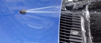
The vehicle is operated in different climatic and road conditions. For safe and comfortable movement, the driver must have good visibility of the road situation, i.e. the windshield must always be clean. Windshield wipers provide mechanical cleaning of the windshield from dirt and sediment, improving visibility and increasing safety. We will consider possible problems with this mechanism and ways to eliminate them in more detail.
Principle of operation
The work of the wipers is quite simple and consists of the following sequence of actions:
- The driver selects the desired operating mode of the windshield wipers using the steering column switch.
- The entire windshield cleaning mechanism is driven by a motor.
- The wipers move across the glass left and right at the selected speed, cleaning the surface.
- When the mechanism is no longer needed, the steering column switch returns to its original position.
Wiring diagram for the wipers and windshield washer of the VAZ 2107: 1 - thermo-bimetallic fuse; 2 — windshield wiper gearmotor; 3 — electric motor for windshield washer; 4 — mounting block; 5 — washer switch in the three-lever switch; 6 — wiper switch in a three-lever switch; 7 — windshield wiper relay; 8 — ignition switch;
Find out more about glass on the VAZ-2107: https://bumper.guru/klassicheskie-modeli-vaz/stekla/lobovoe-steklo-vaz-2107.html
Components
The windshield wiper consists of the following main elements:
- lever mechanism (trapezoid);
- electric motor;
- relay;
- brushes
Trapezoid
One of the important elements in the windshield wiper mechanism is the trapezoid. On almost all cars this part is the same, and the difference lies only in the methods of fastening, the size and shape of the elements. The functioning of the trapezoid consists of transmitting rotational motion from the electric motor to the wipers, as well as ensuring the synchronous movement of the latter for high-quality glass cleaning. The trapezoid consists of rods, a body and a hinge.
Trapezoid design: 1 - crank; 2 - short thrust; 3 — joint of rods; 4 — rollers of the windshield wiper mechanism; 5 - long pull
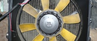
Motor
The electric motor of the windshield wipers of the VAZ “Seven” is made as a single unit with a gearbox and is one of the main links of the mechanism in question. The motor consists of a stator with permanent magnets and an armature with an elongated shaft, at the end of which a screw is threaded. The purpose of this unit is to ensure the movement of the blades along the windshield. The device is considered reliable and fails very rarely.
Wiper relay
On classic Zhiguli cars, the windshield wiper has two operating modes - fast and intermittent with an interval of 4-6 seconds. It is to ensure intermittent operation that the RS 514 breaker relay is designed. Delayed activation of the wipers is used during light rain, when too frequent operation of the windshield wipers is not required, and when the mechanism is completely turned off, the glass is gradually covered with small drops of precipitation and needs to be cleaned. The product is connected to the general wiring using a four-pin connector. On the VAZ 2107, the breaker relay is located on the driver’s side on the left side panel under the plastic trim.
The wiper relay ensures intermittent operation of the mechanism
Brushes
Almost all passenger cars use two windshield wiper blades. On the “seven”, elements with a length of 33 cm are installed from the factory. Longer brushes can be installed, but a greater load will be placed on the electric motor, which will lead not only to slower operation of the mechanism, but also to possible failure of the motor.
The VAZ 2107 is equipped with brushes 33 cm long from the factory.
Why does the windshield washer not work?
All washer malfunctions are divided into two groups: electrical and mechanical.
Mechanical:
- Lack of liquid. In winter, you cannot use ordinary water, as it may freeze. If the water still freezes, you need to warm up the car engine and leave it in a warm room.
- The fluid supply hose may fly off or become pinched.
- The nozzles can also stop the washer from working. Poor quality of water and washer fluid leads to the fact that the fittings become clogged with dirt, rust, and washer fluid does not flow. The injectors are cleaned or new ones are purchased.
Electrical:
- Fuse F2(10A) has blown.
- The electric motor does not pump, no fluid flows, which means the terminals are oxidized. You need to clean the terminals and contacts and connect everything.
- Faulty switch. If the motor does not turn when voltage is present, then this is the reason.
- Check the pump motor by connecting it directly to the battery; if it starts spinning, then the fault is in the steering column switch.
We disassemble the turn switch for a VAZ 2107
And although many manufacturers of turn switches claim that this is a completely non-separable design, it can still be disassembled with some effort. Disassembly of devices is necessary when repairing it. It takes place in several stages:
- Using a 3 mm drill, drill out the 2 upper rivets and remove the upper part that is attached to the tube;
- After removing this part we see 2 more rivets that hold the ring;
- Carefully remove the ring from the grooves, then you need to remove additional rings and levers.
We repair the device
In the VAZ-2107, the switches are located under the steering wheel of the car. If you suspect a malfunction, the first thing you need to do is find out the reason why this or that function does not work.
Repairing the switch
We remove the steering column switch on the seven. Having removed the first ring, then the headlight, stop and wiper levers, we get to the mechanism by which the turns are automatically turned off. We take it out and here lies the cause of all the troubles: between the reeds there is a spring that breaks off and does not move the reeds in different directions. It is necessary to replace the spring; you can use a regular spring from a ballpoint pen. Next, we begin collecting all the rings and levers in reverse order. After finishing the work, we check how the levers and the turning mechanism work. To do this, we connect the pads and place the terminals on the battery; if all functions work, then we have completed the repair.
Also, the cause of a malfunction of the turn switch may be contamination or oxidation of the contacts. You can clean dirty or oxidized contacts; to do this, you need to slightly bend the “sagging” springs and other accessible parts. As a rule, after carrying out such cleaning manipulations, it is possible to restore the functionality of the switch.
Malfunctions of VAZ 2107 wipers and their elimination
Various malfunctions can occur with windshield wipers, which manifest themselves in different ways.
The motor has failed
Often, wipers may not function due to problems with the electric motor. Problems often arise due to the accumulation of friction products in the lubricant in the bushings, which leads to its thickening. As a result, the motor armature rotates with difficulty, which leads to burnout of the winding or burnout of the rotor lamellas. Another malfunction is wear of the electric motor brushes. In this case, when voltage is applied, the wipers do not work and sometimes are triggered when you hit the motor with your hand.
Which one can I put?
Instead of the standard “seven” engine, some car owners install a device from a VAZ 2110. This replacement is justified by the following positive qualities:
- greater reliability and power;
- windshield wiper closer;
- 3 speeds (requires a steering column switch from a Chevrolet Niva).
Such an electric motor is installed without any modifications to the mounting in its standard place. However, despite these advantages, some owners of the “classic” note that due to the higher power of the electric motor, the trapezoid breaks down much faster. Therefore, before making changes to the design of the windshield wiper, it is worth performing preventive maintenance on the old mechanism (clean the trapezoid from dirt and lubricate the rubbing elements and the motor itself with the gearbox).
The standard device also copes quite well with its tasks if it works properly.
Removing the motor
The windshield wiper motor is located behind the partition of the engine compartment on the left side. To dismantle the mechanism, you need to prepare the following list of tools:
- open-end or socket wrench 22;
- socket head 10;
- small extension cord;
- crank or ratchet handle.
We remove the part in the following order:
- Pull the terminal off the battery negative.
- Using a 10mm wrench, unscrew the nuts holding the wiper arms.
Motor repair
To troubleshoot the electric motor elements, it must be disassembled.
The only tools you need are a set of screwdrivers. We disassemble the node in the following order:
- Unscrew the screws securing the plastic cover.
Trapezius problems
The fact that problems have arisen with the windshield wiper trapezium is indicated by interruptions in the operation of the wipers. They can appear in the form of an arbitrary stop during operation or too slow movement of the brushes. In addition, a sign of problems with the trapezoid are jumps or extraneous sounds during operation. The problem is caused by the appearance of oxide in the trapezoid bushings, as well as corrosion on the axles. If such faults are neglected, then over time the electric motor will fail due to high loads.
Mechanism repair
To remove the trapezoid, we perform a similar sequence of actions as when dismantling the windshield wiper motor. The only tool you need is a flat screwdriver. We disassemble the mechanism in the following order:
- We remove the stoppers from both shafts by prying them up with a screwdriver.
Video: replacing the trapezoid on the “seven”
Correct installation of the trapezoid position
After carrying out repair work on the trapezoid, you need to set the correct position of the mechanism. To do this, perform the following steps:
- We set the motor to the initial position, for which we connect the block with wires, turn on the windshield wiper mode using the steering column switch, turn it off and wait until the electric motor stops.
Video: adjusting the position of the wipers
Wiper relay not working
When there is no intermittent operation of the windshield wiper, the main reason is a breakdown of the breaker relay. The way out of the situation is to replace the device.
Relay replacement
To remove the relay you will need a Phillips and flathead screwdriver. We carry out the work in this order:
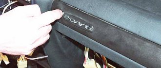
- Use a screwdriver to pry up the side panel holders and remove it.
Wiper switch malfunction
The “seven” steering column switch is responsible for enabling the following functions:
- turns;
- head lighting;
- wipers and windshield washer.
The switch is highly reliable and fails extremely rarely. However, sometimes it still has to be changed and this happens due to burnt contacts or wear of individual elements of the mechanism. To work you will need the following list of tools:
- head 24;
- head or key 8;
- crank or ratchet;
- flat screwdriver.
Switch replacement
To replace the switch, perform the following sequence of actions:
- Use a screwdriver to pry up the decorative steering wheel trim and remove it.
Fuse burned out
A common cause of wipers not working is a blown fuse. On the VAZ 2107, the operation of the windshield wipers is controlled by a 10 A fuse link F2 located in the fuse box.
The mounting block is installed under the hood near the windshield on the right side.
Checking and replacing the fuse
If the wipers stop functioning, then first of all it is worth checking the integrity of the protective element. To do this, you can use a multimeter by turning it on to dialing mode. If the part is working properly, then the resistance will be zero. Otherwise, the element needs to be replaced.
Why does the fuse burn?
Sometimes it happens that a fuse-link burns out for no apparent reason. In this case, you need to check the entire electrical circuit from the power source to the motor. Failure of the fuse indicates a short circuit, i.e. too high current consumption exceeding the rating of the protective element. The problem can also be caused by a short circuit in the wiring to the housing, jamming of the trapezoid due to lack of lubrication in the rods, which indicates the need for inspection and preventive maintenance of the mechanical part of the unit.