On a VAZ 2105 car, mainly two types of fuse mounting blocks were installed, conventionally called the old or new model.
On cars with injection engines, additional fuses were used to control the operation of electrical systems. In many ways, the blocks were unified with analogues on other classics.
Old style block
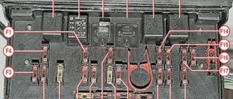
With the exception of very ancient and rare first copies, switching units, also called black boxes, for the VAZ 2105 were mounted outside the engine panel on the right, and wiring from the engine compartment to the control units passed through them. Initially, cylindrical fuses were used, like the first VAZs, of two ratings, 8A and 16A.
All seventeen fusible links stood in a row at the front wall of the case. The location and distribution of loads was also similar to its predecessors.
| Serial number | Denomination, A | Connected Circuits |
| 1 | 8 | Reversing lights, heater, glass heating switching |
| 2 | 8 | Pumps and wipers |
| 3 | 8 | Reserve |
| 4 | 8 | Reserve |
| 5 | 16 | Glass heating threads |
| 6 | 8 | Cigarette lighter circuit and additional connector |
| 7 | 16 | Horn and electric cooling fan |
| 8 | 8 | Turn signal and emergency |
| 9 | 8 | Fog lights and starting the generator |
| 10 | 8 | Instruments, visor and turn alarms |
| 11 | 8 | Brake light circuit, interior light |
| 12 | 8 | Far right, cleaning headlights |
| 13 | 8 | Far left, far control |
| 14 | 8 | Dimensions left front and right rear, size alarm, license plate illumination, engine compartment light |
| 15 | 8 | Dimensions on the right front and left rear, lighting of the dashboard, cigarette lighter and glove box |
| 16 | 8 | Middle right, headlight cleaning switch |
| 17 | 8 | Middle left |
The fastening of outdated type fuses was not reliable, which was in no way compensated by the simplicity and clarity of their replacement. Therefore, the design was soon changed.
Starter
Starter 35.3708 Assembled
1 - drive side cover; 2 - retaining ring; 3 — restrictive ring; 4 — drive gear; 5 — overrunning clutch; 6 — drive ring; 7 — rubber plug; 8 — drive lever; 9 — relay anchor; 10 — holding winding of the traction relay; 11 — pull-in winding of the traction relay; 12 — relay coupling bolt; 13 — contact plate; 14 — relay cover; 15 — contact bolts; 16 - collector; 17- brush; 18 — armature shaft sleeve; 19 — cover from the collector side; 20 - casing; 21 — shunt coil of the stator winding; 22 — body; 23 — stator pole fastening screw; 24 — anchor; 25 — armature winding; 26 - intermediate ring.
A starter is installed on a VAZ-2105 car - a four-pole four-brush DC electric motor with mixed excitation, with a device for connecting and disconnecting the starter drive gear with the flywheel ring gear. The starter is turned on by an electromagnetic traction relay with remote control.
The starter is bolted to the clutch housing on the right side of the car engine with three bolts. It is protected from the heated exhaust pipe by a heat-insulating shield.
Starter connection diagram
1 - generator; 2 - battery; 3 - starter; 4 — starter activation relay; 5 — mounting block; 6 — ignition switch; P1 - pull-in winding of the traction relay; P2 - holding winding of the traction relay.
Technical characteristics of starter 35.3708* (ST-221)
| Rated voltage, V | 12 |
| Rated power, kW | 1,3 |
| Current consumption at maximum power, no more, A | 290 (260″) |
| Current consumption in the inhibited state, no more, A | 550 (500″) |
| Current consumption in idle mode, no more than, A | 60 (35″) |
* With end manifold.
** For ST-221 starter.
The starter housing and covers are secured with two bolts. Bronze-graphite bearings (bushings) are installed in the front and rear covers, in which the armature shaft rotates.
The torque from the starter armature shaft is transmitted to the engine crankshaft flywheel through the starter drive.
The traction relay is necessary to engage the drive gear with the flywheel ring gear and turn on the power to the starter motor. When the ignition key is turned to the “starter” position, voltage is supplied to both windings of the traction relay (retracting and holding). After closing the contacts of the traction relay, the power to the pull-in winding is turned off.
A roller freewheel clutch (overrunning clutch) with a drive gear is installed on the drive shaft. It transmits torque in only one direction - from the starter to the car engine, separating them after the engine starts. This is to protect the starter from damage due to excessive speed.
Possible malfunctions, their causes and methods of elimination
| Cause of malfunction | Elimination method |
| When the starter is turned on, the armature does not rotate, the traction relay does not operate | |
| 1. The battery is faulty or completely discharged | 1. You need to charge the battery or replace it with a new one |
| 2. The battery terminals and wire tips are heavily oxidized; tips are loosely tightened | 2. It is necessary to clean the pole terminals and wire tips. Tighten and lubricate with Vaseline |
| 3. Interturn short circuit in the pull-in winding of the traction relay, shorting it to ground or breaking | 3. Replace the traction relay |
| 4. Open circuit in the power supply circuit of the starter traction relay | 4. Check the wires and their connections in the circuit between plugs “50” of the starter and ignition switch |
| 5. Contacts “30” and “50” of the ignition switch do not close | 5. It is necessary to replace the contact part of the ignition switch |
| 6. Jamming of the traction relay armature | 6. Remove the relay, check the ease of movement of the armature |
| 7. The starter relay is faulty | 7. It is necessary to clean the relay contacts. A faulty relay needs to be replaced |
| 8. Open circuit in the power supply circuit of the starter relay winding | 8. Check the wires and their connections in the circuit between plug “50” of the ignition switch and plug “86” of the relay |
| When the starter is turned on, the armature does not rotate or rotates too slowly, the traction relay is activated | |
| 1. Battery is faulty or discharged | 1. The battery needs to be charged or replaced with a new one |
| 2. The battery poles and wire tips are oxidized; tips are loosely tightened | 2. Clean the pole terminals and wire lugs, tighten and lubricate with Vaseline |
| 3. The lugs of the wire connecting the power unit to the body or to the negative terminal of the battery are loose. | 3. Tighten the fastenings of the wire lugs |
| 4. The contact bolts of the traction relay are oxidized or the nuts of the wire lugs on the contact bolts are loose | 4. Clean the contact bolts, tighten the fastening nuts |
| 5. Burnt commutator, stuck brushes or worn out brushes | 5. Clean the commutator, replace the brushes |
| 6. Open circuit or short circuit in the stator or armature windings | 6. The stator or armature needs to be replaced |
| 7. Short circuit of the brush holder of the “positive” brush to ground | 7. Repair the short or replace the manifold side cover |
| When the starter is turned on, the traction relay is activated and switched off repeatedly | |
| 1. Battery is low | 1. Charge the battery |
| 2. Large voltage drop in the power circuit of the traction relay due to severe oxidation of the wire tips | 2. Check the wires and their connections in the circuit from the battery to plug “50” of the starter |
| 3. Open or short circuit in the holding winding of the traction relay | 3. Replace the traction relay |
| When the starter is turned on, the armature rotates, the flywheel does not rotate | |
| 1. Freewheel slipping | 1. Check the starter on the stand, replace the clutch |
| 2. Breakage of the clutch engagement lever or its axis jumping out | 2. It is necessary to replace the lever or replace its axle |
| 3. Breakage of the coupling drive ring or buffer spring | 3. Replace the coupling |
| Unusual starter noise when turning armature | |
| 1. The starter is loose or its cover on the drive side is broken | 1. Tighten the fastening nuts or repair the starter |
| 2. The starter is mounted skewed | 2. Check the starter mounting |
| 3. Excessive wear of bearing bushings or armature shaft journals | 3. Replace starter |
| 4. The stator pole is loose (the armature touches the pole) | 4. Tighten the pole fixing screw |
| 5. Damaged drive gear teeth or flywheel rim | 5. The drive or flywheel needs to be replaced |
| 6. The gear does not disengage from the flywheel: — jamming of the drive lever: — jamming of the coupling on the spokes of the armature shaft; | 6. Do the following: - replace the lever: — clean the splines and lubricate them with engine oil; |
| — the clutch or traction relay springs are weakened or broken: | — replace the clutch or traction relay: |
| — the retaining ring has jumped off the coupling hub; — jamming of the traction relay armature; | - replace damaged parts: - replace the traction relay or eliminate the jam |
| — the contact part of the ignition switch is faulty: contacts “30” and “50” do not open | -check the correct closure of the contacts at different key positions; irreparable contact part replace |
Checking the starter on the stand
In order to ensure that the starter is operating efficiently, it is necessary to check its electrical and mechanical data on a bench.
The electrical connection diagram for checking the starter on the bench is shown in the figure. The connecting wires to the current source, ammeter and contact bolt of the starter traction relay must have a cross-section of at least 16 mm2.
Connection diagram for testing the starter on a stand
1 - voltmeter with a scale limit of at least 15 V; 2 - starter; 3 - rheostat 800 A; 4 - ammeter with a 1000 A shunt; 5 - switch; 6 - battery
The starter must be powered from a fully charged 6ST-55 battery or from a special current source, the voltage drop characteristic of which under load corresponds to the voltage drop characteristic of the 6ST-55 battery.
The starter temperature during checks should be (25±5) °C, and the brushes should be well ground to the commutator.
Checking the functionality of the starter
By closing switch 5, at a current source voltage of 12 V, turn on the starter three times with different braking conditions. For example, at braking torques of 2, 6 and 10 N•m (0.2, 0.6 and 1 kgf•m). The duration of each starter activation should be no more than 5 s, and the intervals between activations should be no less than 5 s.
If the starter does not rotate the gear ring of the stand or its operation is accompanied by abnormal noise, it is necessary to disassemble the starter and carefully check its parts.
Starter test in full braking mode
Brake the ring gear of the stand, turn on the starter and measure the current, voltage and braking torque, which should be respectively no more than 550 A, no more than 7.5 V and no less than 13.7 N•m (1.4 kgf•m). For the ST-221 starter, the current should be no more than 500 A and the voltage no more than 6.5 V.
The duration of activation of the starter should be no more than 5 s.
If the braking torque is lower and the current strength is higher than the specified values, then the reason for this may be an interturn short circuit in the stator and armature windings or a short circuit of the windings to ground.
If the braking torque and current consumption are below the above values, the reason may be oxidation and contamination of the commutator, loosening of the stator winding terminals, severe wear of the brushes or a decrease in the elasticity of their springs, hanging brushes in the brush holders, oxidation or burning of the contact bolts of the traction relay.
When the gear is fully braked, the starter armature should not turn. If the gears turn, the freewheel is faulty.
To troubleshoot, it is necessary to disassemble the starter and replace or repair damaged parts.
Testing the starter at idle speed
Remove the gear ring of the stand from engagement with the starter gear. Turn on the starter and measure the current it consumes and the speed of the starter armature. They should be respectively no more than 60 A (35 A for the ST-221 starter), and 5000±1000 min-1 with a voltage at the starter terminals of 11.5-12 V.
If the current strength and rotation speed of the armature shaft differ from the specified values, the reasons may be the same as during the previous test.
Checking the traction relay
Install a 12.8 mm thick spacer between restrictor ring 21 (see Figure 7-16) and the gear and turn on the relay. Check the relay switching voltage, which should be no more than 9 V at an ambient temperature of (20±5) °C. If the voltage is higher, this indicates a faulty relay or drive.
Until 1983, a single-winding traction relay was installed on ST-221 starters. For a starter with such a relay, check the current consumption, which should be no more than 23 A.
Checking the mechanical data of the starter
Check the spring pressure on the brushes with a dynamometer. For new brushes it should be 9.8±0.98 N (1±0.1 kgf). If the brushes are worn to a height of 12 mm, they must be replaced by first rubbing them into the commutator.
The axial free play of the armature shaft should be no more than 0.5 mm (0.07-0.7 mm for the ST-221 starter). If it is not within this limit, it is necessary to disassemble the starter and select the thickness and number of adjusting washers.
The starter drive must move freely, without noticeable jamming, along the splined end of the armature shaft and clearly return from the operating position to the original position under the action of the relay armature return spring.
When the drive gear is turned in the direction of rotation of the armature, the armature should not rotate. The gear must rotate relative to the armature shaft under a torque of no more than 27.4 N•cm (2.8 kgf•cm).
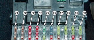
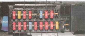
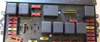
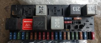
New sample block
All functionality, dimensions and connection of the unit were preserved. The fuse block has been converted to midi-format knife-type inserts with flat contacts used throughout the world for a standard 6.3 mm connector. The black box layout has also changed. Euro fuses could last much longer.
The ratings were also brought to the standard series in three values - 7.5, 10 and 20 A. The same seventeen inserts were already arranged in two rows, four spare fuses and plastic tweezers stood separately, making them easy to replace. The circuit switching scheme has not changed, with rare exceptions.
For example, the principle of supplying power to the generator excitation winding was changed. The use of this device with a built-in relay regulator made it possible to exclude power supply to the circuit through a fuse; the initial current was set by a control lamp of increased power.
The interchangeability of new and old blocks on different machines is conditional. Minor changes in the electrical circuits of cars may require minor modifications to the units by an auto electrician or independently. This applies to the switching of starter circuits, radiator fan, fog lights and window wipers.
On some blocks, jumpers were installed instead of individual relays, or vice versa. The fact is that the switching elements could ensure the operation of devices without intermediate relays; the current flowed directly to the consumer, which simplified the design. The price was significantly reduced.
Additional items
h23,0,0,0,0—>
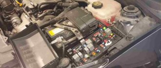
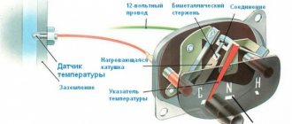
Under the hood
h34,0,0,0,0—>
Additional headlight wiper fuses (2A rating) protect the motor windings. They are located on the supply wires next to the gearmotors.
p, blockquote18,0,0,0,0—>p, blockquote19,0,0,0,0—>
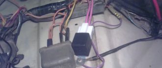
The starter activation relay 113.3747 or 90.3747-10 is located in the engine compartment on the right mudguard.
p, blockquote20,0,0,0,0—>p, blockquote21,0,0,1,0—>
In the cabin
h35,0,0,0,0—>
The windshield wiper relay (PC-514) is mounted under the panel on the left under the trim.
p, blockquote22,0,0,0,0—>p, blockquote23,0,0,0,0—>
The ignition relay and the hazard warning and turn signal relays are installed on the front panel behind the instrument panel. The ignition relay (113.3747-10 or 90.3747-10) and the hazard warning and turn signal relays (23.3747 or 231.3747) have a bracket for direct mounting on the body.
p, blockquote24,0,0,0,0—>p, blockquote25,0,0,0,0—>
The fog lamp fuse is located in the gear shift compartment, not far from the radio.
p, blockquote26,0,0,0,0—>p, blockquote27,0,0,0,0—>
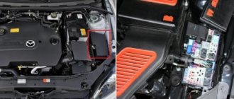
VAZ 2105 and 2107 with injection engines
More modern and environmentally friendly 21067 engines with distributed fuel injection have complicated the electrical equipment of cars, which has led to the use of additional fuses. On new cars it was also possible to use a central lock.
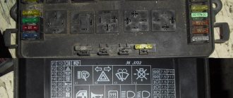
The three fuses for the injection control circuits are located in a single block with three main relays - the main relay, the fuel pump relay and the cooling fan relay. These are 15A inserts that protect the power supply to the main relay, the relay for the fuel pump and the entire unswitched power supply circuit of the engine controller. The injector has its own individual requirements.
A little earlier, two additional fuses appeared in cable-type holders, embedded in the circuits of the headlight glass cleaning motors. This was due to cases of mysterious battery discharge due to jammed gearmotors on the headlights. The new fuses were located near the rear right and left headlight housings. Everyone is responsible for their own side.
Location of fuses in the car
Fuses in a car are usually located in places that are strictly regulated by the designer, but the most common location is the lower part of the instrument panel in the cabin. To detect them, simply pull back the plastic cover of the instrument panel, which is marked, and then carry out the necessary manipulations.
To carry out any actions with fuses, you should isolate the mounting block from static electricity, as it can give a strong discharge and cause all fuses to blow.
How to make a replacement
Sometimes fuses require replacement, even if the circuit they protect is in good condition. The fuse rating is calculated accurately enough so that if the current consumption increases even by several tens of percent, additional damage will not be caused to the car.
But a short-term increase in the current flowing through the fuse is quite possible even in normal situations. Inrush current in electric motors, increased consumption by lamps when the filaments heat up, overheating of the fuse housing due to poor contact in its connector, and finally, manufacturing defects and increased nominal tolerances. Sometimes it can even be due to natural aging, as well as an installation error.
The block cover is installed on a plastic latch. Not very convenient, but it is quite possible to open it. The main thing is not to forget to close it later, since electrical appliances really do not like dirt and moisture.
There is a notice on the inside of the lid that indicates where each device is located and its operating current. This data must strictly correspond to reality, otherwise the above-mentioned troubles are possible. The new type of fuses are usually made of transparent plastic, which makes it possible to determine their integrity even visually. But not always. Sometimes the break cannot be seen with the eye. You can use a multimeter in ohmmeter mode or a test light.
The easiest way is to measure the resistance of the removed fuse with an ohmmeter. The device should show a resistance of about zero. No more than his own readings with the probe tips short-circuited among themselves. You can compare it with a known-good fuse in stock.
A certain convenience is the color coding of denominations. But you shouldn’t trust it blindly; the main thing is the number indicated on the end of the case. The new insert must be marked in the same way as the diagram allows, since the failed insert could also be selected incorrectly.
If the new fuse also fails, further replacements are pointless. It is necessary to look for and eliminate faults in the instruments, instrument panel or wiring itself.
Electrical diagram of VAZ 2104 early models
Early 2104 versions differ from later versions in the following ways:
- they have a G-222 generator unit installed;
- a 10-pin switch is used to control the light alarm;
- the version is supplemented with a top dead center controller for cylinder 1;
- to protect the electrical circuit of the light signaling and turning lights, a five-contact relay is used;
- presence of a connector for diagnostics;
- use of an indicator light source for the rear window heating system;
- the presence of a two-position external lighting switch, as well as a three-position light switch, the devices are located under the steering column.
Equipment diagram for the first VAZ 2104 models
Description of the scheme:
- Head optical devices.
- Car side turning lights.
- Battery.
- Relay for protecting the electrical circuit of the battery warning light indicator.
- Electric pneumatic valve of a carburetor device.
- Cylinder 1 top dead center controller.
- Microswitching device of a carburetor unit.
- Generator unit G-222.
- Gear motors for the front optics cleaning system.
- Electric motor of the ventilation device of the cooling system of the power unit.
- Fan motor activation and deactivation controller.
- Sound signals.
- Distributor or distribution unit of the ignition system.
- Candles.
- Starter.
- Controller for coolant temperature level indicator in the engine cooling system.
- Underhood light source to provide light in the engine compartment.
- Engine fluid pressure indicator light controller.
- Ignition coil.
- Brake fluid volume determination controller.
- Windshield wiper motor.
- Control module for an electric pneumatic valve of a carburetor unit.
- Electric motor for the pumping device of the optics washing system.
- Windshield washer pump motor.
- Diagnostic output for fault detection.
- Stop light switching device.
- Windshield wiper system intermittent relay. Thanks to this device, the wipers operate at a certain interval, which can vary.
- Intermittent device for light signaling and turning lights. Its operating principle is identical to the windshield wiper relay.
- Reverse light switch.
- Plug socket designed to connect a portable lamp.
- Cigarette lighter.
- Light activation lamp in the glove compartment.
- Safety module. It uses a jumper instead of a short circuit relay.
- Switching devices for lamps on pillars in the front doors.
- Switches in the lighting fixtures located in the rear door pillars.
- Lighting devices in lampshades.
- Switch element for handbrake warning light.
- Switch for the cleaning device, as well as the rear window washing system.
- Switch button for activating and deactivating the light alarm.
- Three-lever switch device.
- Egnition lock.
- Switching device for the control panel lighting system.
- External lighting switch.
- Switch element for rear fog lights.
- Control light indicator of the level of engine fluid pressure in the lubrication system.
- Control panel with sensors and light indicators.
- Indicator of fuel reserve in the tank.
- Gasoline level control sensor.
- Lighting device for the rear part of the cabin.
- Light source for battery charging.
- Refrigerant temperature level control sensor.
- Interrupting device for handbrake control light indicator.
- A module in which lighting lamps are installed.
- Indicator of brake fluid volume in the system.
- Rear fog lamp indicator light.
- A light on the dashboard indicating that the handbrake is activated and released.
- Voltmeter.
- Speedometer.
- Indicator for activation and deactivation of external lighting.
- Control light source for turning lights.
- The high beam activation indicator is located in the instrument panel.
- Switching device for the stove fan.
- Rear window heating switch with activation control light source.
- Electric motor for the stove ventilation device.
- Additional resistor device for the electric motor of the heating unit.
- Rear window cleaning system pump motor.
- Rear optics in a car.
- Motorized rear window cleaning system.
- Connectors for connecting to the rear window heating system.
- Rear license plate lighting optics.
- Controller for determining the level and reserve of fuel in the tank.