Historical excursion
Hydraulic compensators, also known as hydraulic pushers, or in common parlance “hydriki”, appeared quite a long time ago. Let's look at why compensators are needed and how they appeared in the engines of many cars.
Drivers largely owe their appearance in the design of gas distribution mechanisms of cars to Japanese auto engineers, since it was they who began to massively use “hydraulic valves” in the design of engine timing systems. At that time, when designing an internal combustion engine, much attention was paid not only to its main components (crankshaft, pistons, connecting rods), but also to the details of the gas distribution mechanism. Engineers gradually “brought” previous generations of their power units to perfection. Thus, hydraulic pushers replaced the usual mechanical pushers.
What are the types of hydraulic compensators?
These devices are widely used in timing systems. However, their analogues are also used in chain tensioning, the so-called “ timing chain ”. For this period of time, only 4 designs are used.
- Hydraulic pusher. Often used on modern cars to adjust the gap between the valve and the camshaft
- Hydro support
- Hydraulic support for installation in levers and rocker arms. Mainly used on old timing mechanisms
- Roller hydraulic pusher
All 4 types can be found on various designs, although “hydraulic mounts” were often used earlier in engines. Now everything is more. It’s a little clear about the types, now let’s learn more about how they work.
How do hydraulic compensators work?
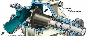
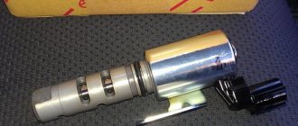
The hydraulic compensator device (hydraulic support) is a cylindrical metal structure. On the outside, the compensators do not have any characteristic elements (with the exception of roller-type compensators).
The entire mechanism of this part is hidden inside: there is a spring-loaded plunger and its valve (ball), a separate spring for this unit (plunger pair), and for the compensator to work, there is a special channel through which oil is supplied from the cylinder head. There is also a special compensation container in the inner part, where oil accumulates when the camshaft cam presses the compensator. This compensation capacity acts as a kind of storage device and works as a damper.
In situations where the camshaft cam does not press on the hydraulic compensator, the compensator comes into contact with the camshaft due to the work of the spring and the plunger pair. The damper is filled with oil, but this amount is not enough for the plunger pair to operate. The oil channel in the compensator is closed, and the pressure inside does not exceed such a mark that there is pressure on the timing valve.
The outer part of the compensator is in contact with the profile (cam) of the camshaft and constantly moves, thus determining the moment and time for which the valve will be open. At the moment of operation , the camshaft cam presses on the compensator body, thereby overcoming the force from the spring and the plunger pair, and opening the oil channel necessary for the operation of the plunger pair.
Thus, when the camshaft cam is pressed on the compensator, oil flows into the compensator, the pressure in it increases and its operation is to open the timing valve at the right time. The plunger pair acts as a regulator and immediately after the cam passes a certain point on the shaft, it begins to “bleed” excess oil back into the system. As a result, due to the operation of the plunger pair, the pressure difference and thermal expansion of the metals, the required gap is selected and the compensator is pressed against the camshaft.
Why are hydraulic “adjusters” needed?
As the engine gradually reaches operating temperature, its other components also heat up. The associated expansion of parts causes a decrease in a variety of gaps in the power unit. And adjusting the gaps in the gas distribution mechanism is a very important operation, since the stability of the engine largely depends on it. It is clear that manual adjustment is a tedious and ineffective task; special mechanisms cope with it much more successfully. Moreover, during active vehicle operation, the valves are constantly under both mechanical and thermal load. And we must not forget that all timing components heat up unevenly, which, combined with natural abrasion, leads to increased wear of the valve mechanism.
The operating principle of hydraulic valve compensators is based on ensuring optimal thermal clearance. But it should be different, since the intake valves, compared to the exhaust valves in contact with hot gases, heat up an order of magnitude less. In addition, “regulators” are able to take into account the wear of the valve mechanism, although this does not solve the problem of increased fuel consumption and a decrease in engine power.
Returning to the issue of manually adjusting the timing belt, one cannot help but notice that such an adjustment should be carried out after 15 thousand km. However, it is highly not recommended to carry out such a procedure without very specific skills, since it is necessary to take into account a wide variety of temperature fluctuations. This is the same as in the case of the average temperature in the ward, which does not provide objective data on the condition of the patients. And a completely different matter are hydraulic compensators that regulate the gap automatically, taking into account current parameters.
Malfunctions
Drivers of modern cars equipped with engines with hydraulic pushers often encounter problems with knocking expansion joints. Typically, such malfunctions appear at mileages of over 40,000 km or more. Why do hydraulic compensators knock? There can be many reasons for the appearance of the ill-fated clatter, let’s look at them in order.
- Using low quality oil. and/or untimely replacement of fuel and lubricants.
When cheap and low-quality oils are poured into the engine, the hydraulic compensator parts are subject to premature wear: the oil channels and the compensator valve (ball) become clogged, which is why the compensator does not close completely. In addition, with low-quality oil and improper operation of the plunger pair, oil leaks and incorrect clearance selection often occur.
- Untimely replacement of fuel and lubricants.
Rare engine oil changes are also one of the reasons for knocking compensators. Oil that has lost its working properties is prone to burning and coking, which is why deposits on the walls of the channels interfere with the normal passage and outflow of oil from the compensators.
- Insufficient oil in the system.
Car owners should not forget that it is necessary to constantly monitor the oil level in the engine using a dipstick, and it is recommended to do this every time you open the hood, since this procedure does not take more than two minutes. Therefore, when a clattering noise appears from under the valve cover, you should first check the oil level.
Different models of power units have their own typical “sores”, one of which is oil leaks. And if such design flaws in modern engine models can be found extremely rarely, then problems with consumables are much more common. The use of non-original or low-quality oil seals and gaskets can cause oil leaks and a decrease in overall oil pressure. Therefore, you should not be surprised if, when the cylinder head cover is “fogged up” or when there are leaks on the cylinder block, the compensators begin to knock. In addition to current seals and gaskets, a problem area can also be a faulty oil filter, due to which the pressure in the system drops and the oil does not flow well into the compensator wells.
- Compensator failures.
Failure of expansion joints on foreign cars is not a frequent occurrence, but when operating in the conditions of the Russian Federation and the CIS, it still happens. There are two main reasons here: - low-quality fuels and lubricants (fake or cheap oil, low-octane gasoline with harmful additives, etc.); - a cheap (unreliable) manufacturer of the compensators themselves.
The use of low-quality fuels and lubricants leads to the fact that hydraulic pusher elements simply fail over time: - the plunger pair jams; — the plunger spring fails.
- Natural wear and tear.
With a long mileage of hydraulic pushers (over 60,000 - 70,000 km), the internal parts of the compensator wear out, resulting in oil leaks from the internal cavity of the part. Also, on such runs, it is not uncommon for the plunger pair to jam, which often results in a parasitic clattering sound.
Pros and cons of a hydraulic compensator
There are many positive aspects to this mechanism:
- It is completely maintenance-free and works automatically
- Increased timing system resource
- Maximum pressure, which gives good traction
- Minimum fuel consumption
- The engine always runs quietly
Well, despite all the advanced design, there are also a fairly large number of disadvantages.
- Since all work is based on oil pressure, you need to fill in only high-quality lubricants. Synthetic is desirable
- Need to change oil more often
- The design is more complex
- Expensive repairs
- Over time, they can become clogged, which impairs engine performance (consumption and traction), and the timing belt begins to make noise.
The biggest disadvantages are that the design is expensive and complex, and is VERY demanding on the quality of the oil. If you pour “don’t understand what” they will very quickly fail and require replacement. For example, conventional mechanical pushers are much simpler and less demanding on the quality of lubrication.
Say a word about cold starts
Many car owners often complain that when starting the car engine in winter, a characteristic clattering sound of hydraulic compensators occurs. The occurrence of this parasitic knock when starting the engine “cold” is a common situation due to the following points: - use of high-viscosity oil; — starting the engine without preheating (in a warm garage, or using a preheater); — starting the car at subzero temperatures (below -10-15 degrees).
Using oil with high viscosity at low temperatures makes it much more difficult for the crankshaft to crank the engine. The secondary shaft and the drive of additional units suffer from the same problem, so the viscous oil, when starting the engine, dilutes for quite a long time and reaches the compensators.
It is worth remembering that starting the engine at subzero temperatures is always more difficult, so it is recommended to install pre-heaters or park the car in heated garages.
If it is not possible to park the car in a warm garage, then you should use engine pre-heaters and fill in oil with a low viscosity. It would also be a good idea to spend a little more time warming up the engine, and after you start driving, avoid heavy loads until the internal combustion engine reaches its “operating” temperature.
Did you like the article? Share on social media networks:
Sequence of washing hydraulic compensators
Hydraulic pushers should be cleaned in a dust-free room. There should be no drafts either. Preparatory work involves searching for 3 containers in which the hydraulic compensator can fit, as well as purchasing flushing fluid - both AI-92 gasoline and kerosene are suitable. In addition, before the procedure, the car should stand in the garage for at least a day in order to get rid of used oil as much as possible. For cleaning you will also need a brush with synthetic bristles. Next, the algorithm of actions is as follows:
disconnect the on-board network from the power supply - disconnect the battery;
remove the air filter and cylinder head cover;
we take out the hydraulic compensator, having previously removed the rocker arm axles.
To rinse the compensator in the first container, immerse it in the poured liquid and press the ball valve. This is usually done using a wire passed through a hole in the plunger. Moreover, accuracy in this matter will not hurt - ill-considered, rough actions can lead to breakage of the spring. Then you should press on the plunger itself, and as soon as the movement becomes easy, squeeze out the valve ball in order to drain the liquid. For more thorough flushing of the channels in the part body, a special syringe is used.
In the second container, the procedure is simply repeated, while the third is needed for testing - this is the final stage. Before installing the washed hydraulic compensator back into the socket, you need to dip it in the flushing liquid, draw it up and lower the valve. Next, the part is removed with the plunger up while pressing on it with your finger - it should be motionless. If there is no movement, you can begin reassembling the engine.
Upon completion of the work, start the engine and let it idle for a few minutes. If the flushing is successful, there will be no knocking noise. It should also be absent after the power unit has minimally warmed up and reached operating temperature.
Principle of operation
The operation of a part can be described in several stages:
- The camshaft cam does not exert pressure on the compensator and is turned with its back side towards it, while there is a small gap between them. A plunger spring inside the hydraulic compensator pushes the plunger out of the bushing. At this time, a cavity is formed under the plunger, which is filled with oil under pressure through a combined channel and hole in the housing. The oil volume is drawn up to the required level and the ball valve closes under the action of a spring. The pusher rests against the cam, the movement of the plunger stops, and the oil channel is blocked. In this case, the gap disappears.
- When the cam begins to turn, it presses on the hydraulic lifter, moving it down. Due to the accumulated volume of oil, the plunger pair becomes rigid and transmits force further to the valve. The valve opens under pressure and the air-fuel mixture enters the combustion chamber.
- During the downward movement, some oil flows out from the cavity under the plunger. After the cam passes the active phase of influence, the work cycle is repeated again.
Operation of the hydraulic compensator
The hydraulic compensator also regulates the gap that occurs due to natural wear of timing parts. This is a simple, but at the same time complex mechanism with precise fitting of parts.
The correct operation of hydraulic compensators largely depends on the oil pressure in the system and the degree of its viscosity. Oil that is too viscous and cold will not be able to enter the pusher body in the required quantity through the channels. Low pressure and leaks also reduce the performance of the mechanism.
Hydraulic pushers: device, photo, description.
General device
The gas distribution mechanism serves for the timely admission of a combustible mixture (gasoline engines) or air (diesel engines) into the engine cylinders and the release of exhaust gases from them in accordance with the requirements of the working process in each of the engine cylinders.
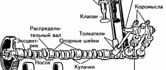
The general structure and operating principle of the gas distribution mechanism is considered using the example of the VAZ engine mechanism (1.2.1).
Rice. 1.2.1 Gas distribution mechanism
The gas distribution mechanism consists of a camshaft 7, which may have a chain or belt drive, levers (rocker arms) 5, the number of which is equal to the number of valves, inlet and outlet valves 1, guide bushings 2, installed in the cylinder head and held in it using retaining rings , valve stem seals, support washers, springs 3, plates 4, crackers, adjusting bolts 9, screwed into threaded bushings 10 installed in the block head. To prevent the bolts from coming loose while the engine is running, they are secured using nuts. To fix and return the levers to their original position, springs 8 are provided. The block head has a special seat for seating the valve 11.
When the camshaft rotates, its cam runs into lever 5, which, turning on the spherical support of the adjusting bolt 9, presses the other end on the valve stem and opens the hole connecting the combustion chamber of the cylinder with the intake (intake valve) or exhaust (exhaust valve) pipeline. With further rotation of the shaft, the cam comes off the lever with its convex part, which, with the help of spring 8, returns to its original position, and the valve closes under the action of the springs.
Valve drive types.
There are several options for transmitting force from the camshaft lobes to the valve stems (i.e., types of valve actuators).
1. Drive through a rod and rocker arm (Fig. 1.2.2) for Renault, early Ford, Volga, Gazelle cars.
Rice. 1.2.2 Valve drive via rod and rocker arms:
1 – valve seat; 2 – valve; 3 – oil deflector cap; 4.5 – valve springs; 6 – spring plate; 7 – cracker; 8 – rocker arm; 9 – adjusting screw; 10 – adjusting screw nut; 11 – rod; 12 – spring support washer
2. Drive through a rocker arm (Fig. 1.2.3) for Mazda-626, ZAZ-1102 cars. With this design, the camshaft cam acts on the rocker arm, at the end of which a roller bearing can be installed to increase service life.
Posts 1 page 17 of 17
Share10/102/2012 10:06
- Author: Kevlark
- Newbie
- Registered: 06/10/2012
- Posts: 28
- Respect: +1
- Time spent on the forum: 7 hours 3 minutes
- Last visit: 08/01/2013 15:20
- Car data: Volkswagen Passat B2
Hello, I am interested in a question. Opening the valve cover, I encountered a problem. Well-known glasses. They interested me and didn’t even intrigue me much. So, this is my first time encountering them.
About the advantages and disadvantages
Why are hydraulic compensators needed? The answer to this question is well demonstrated by the positive aspects of their use:
- from now on there is no need for regular adjustment of valve clearances;
- the load on valves and timing shafts in general has decreased;
- it was possible to achieve a reduction in noise from the operation of the power unit.
Is it worth talking about the shortcomings after this? Of course yes. Let us mention the occurrence of small knocks that can be heard in the first minutes of the engine running “cold”. And this is due to the pressure of the lubricant in the system - while it is cold, it is thicker, and normal filling of the channels occurs after reaching a certain operating temperature.