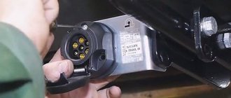
- seven-pin (7 pin) European-type connectors;
- American-type seven-pin (7 pin) connectors;
- thirteen-pin connectors (13 pin);
- special connectors.
The most common types of sockets have 7 and 13 contacts. In Russia, 7-pin devices are usually used, and 13-pin sockets can be seen on many cars from Europe and the USA. The difference lies in the use of additional contacts necessary to activate fog lights and other electrical components of caravans that are popular abroad.
Rules accepted throughout the world provide for the installation of left/right turn signals and stop signals on trailers for passenger cars. The connection diagram for a passenger car trailer socket depends not only on the number of contacts, but also on the standard of the country, so a trailer with European wiring cannot be connected to a socket with Russian wiring without modification. If you install it without modification, then the right dimensions of the BTS will not light up.
Direct connection diagrams
If the towbar and trailer of a passenger car (and truck) are equipped with the appropriate connectors, then the electrical connection diagram will not be needed at all, since you just need to insert the socket into the socket.
Pinout of 7-pin trailer socket Euro and RF
- Left side turn signal.
- Reversing lamp.
- Earth.
- Right side turn signal.
- License plate light and right side marker light.
- Brake light bulbs.
- Right side marker light.
US 7 pin trailer socket pinout
A special feature of the connector is the presence of a reverse contact and the absence of separation between the right and left rows of side lights. In some models of American cars, there is no separation between side lights and brake lights (they run on one wire).
Pinout diagram for 13-pin socket
- Sony Smart Connect - convenient automatic execution of various actions and modes
- Left side turn signal.
- Rear fog lamp.
- Ground for terminals 1 to 8.
- Right side turn signal.
- Left side of dimensions and number plate illumination.
- Brake light lamp.
- The right side of the dimensions and number plate illumination.
- Reversing lamp.
- Constant voltage 12 volts 35 amps.
- The voltage is 12 volts 35 amps, supplied after the ignition is turned on.
- Ground for terminal.
- Signal wire.
- Ground for terminal 9.
Useful: Pinout of diagnostic connector for VAZ cars
When the car is not equipped with a modern electronic control unit. Thanks to this, electrical wires can be directly connected to existing electrical circuits. That is, the wires that come from the connector are connected to those connected to the rear lighting equipment.
Operating rules
In order for the part to last long enough and to avoid problems with the traffic police, the following rules for operating a trailer hitch on a vehicle must be observed:
- Before installing the trailer hitch, you should clarify whether the vehicle manufacturer provides for the installation of this equipment. If you do not do this and do not register changes to the design of the car, then problems with the traffic police may arise.
- When transporting a trailer with a gross weight close to the maximum value, the maximum permissible vehicle speed should not exceed 90 kilometers per hour.
- Regularly check the tightness of the trailer hitch connections. Experts recommend carrying out this operation. Experts recommend carrying out this operation every 1000 km of the vehicle.
- To protect a product that has not been used for a long time from destruction, and to protect it from the negative effects of the environment, use a protective cap and a special lubricant.
- Scratches and chips that occur on the part during operation are covered with a special restorative composition. In addition, moisture, salt and dirt should be removed from it regularly. This is necessary to protect the trailer hitch from corrosion.
With careful use of the trailer hitch, the part will last 10 years.
Electronic matching unit
If we are talking about a modern car with complex electronic components, the first option for connecting a trailer will not be the best choice. The control unit tests the rear optics. When it determines that it is consuming more current, it will display an error message. In such cases, the so-called “matching block” is used. It is also used in the case of transmitting control signals via a multiplex bus.
The wiring is connected to signal circuits, only in this case the signals to the lighting equipment of the towed device come not from the car, but from the matching unit, and its presence is not perceived by the electronics. Additionally, the unit must be connected to a used car.
Installation
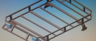
Figure 2-18 shows the main version of the trailer hitch installed on a LADA 4×4 vehicle:
Figure 2-18 – Design and delivery set of LADA 4×4 trailer hitch: 1 – mounting plate; 2 – bushing; 3– rod assembled with brackets; 4 – socket box; 5 – hook
Unscrew bolt 2 on the right and left sides, Figure 2-19, securing bracket 1 of the bumper (replaceable head 19, knob).
Unscrew the rear bolt 3 securing the towing eye 4, if the vehicle has one (replaceable head 17, knob).
Figure 2-19 – Preparation for installation of the trailer hitch: 1– rear bumper bracket; 2 – bracket fastening bolt; 3 – towing eye fastening bolt; 4 – towing eye
Install the trailer hitch bar on the body and secure it to the bumper brackets, without tightening, with standard bolts, having previously installed the thrust bushings from the delivery kit inside the brackets.
Reinstall and tighten the rear towing eye bolt. If the vehicle does not have a towing eye, secure the bar with the bolt and mounting plate supplied (replacement head 17, knob).
Tighten the bolts securing the bumper brackets (replaceable head 19, knob).
Install hook 5 on the rod, see Figure 2-18, and socket 4 (wrench 19, replaceable head 19, knob).
Install and connect the electrical equipment of the trailer hitch
Tightening torques for threaded connections:
- M6 – 9.8 Nm (0.98 kgf/m);
- M8 – 24.0 Nm (2.4 kgf/m);
- M10 – 47.0 Nm (4.7 kgf/m);
- M12 – 81.0 Nm (8.1 kgf/m).
Maintenance of the trailer hitch consists of periodic inspection, tightening of bolted connections, and checking the geometric parameters of the coupling ball.
The frequency of maintenance of the trailer hitch should be carried out in conjunction with the maintenance of the vehicle.
Materials for connecting the tow bar
We go to a car store or car market and buy the materials necessary for installation and connection:
- Connecting car dashboards on the table.
- socket housing for tow bar with cover and rubber O-ring. We pay attention to the normal fit of all parts of the housing, the absence of play or the pressed brass contacts dangling in the sockets, we check the threads and the condition of the fastening screws on the terminals.
- polypropylene or metal corrugated hose for insulating wiring harnesses - 2-3 meters, and a couple of dozen plastic mounting clamps for fixing wiring harnesses.
- silicone gasket, choose color and manufacturer to suit your taste.
see also
Comments 11
I remember I came to buy a trailer. The towbar was in the trunk. While my wife was filling out the paperwork, I installed the tow bar. I connected it according to his instructions - it turned out to be wrong. I connected it according to the trailer instructions - everything works. They could have messed up the wiring in the trailer - I don't know. One hell of a lot, the wiring will have to be changed this spring - the stoppers are dead. So don’t blindly trust the instructions, use the Tseshka or a banal sampler with a light bulb.
By the way, I didn’t know about the rubber plug; I ran the wiring through the left air duct. It needs to be redone.
In principle, they’ve already suggested it, but I’ll add some little additions for completeness...
Driver's side light Black - Red foot+ Green reverse+ Orange/black rear fog lights+ Yellow dimensions+ Blue-black left turn+
Passenger side light Blue is a right turn+
The right turn signal cord stretches through the standard rubber bands to the lights, remove the rubber band, thread the connector, wind up the wire, insert the connector into the headlight, wrap it around the rubber band with electrical tape to the standard wiring, and return the rubber band to its place, under the plastic trim across the trunk, secure the blue wire with electrical tape and that’s it ...
In the towbar socket the numbers are signed, but... 1) left side 2) rear PTF 3) weight 4) right side 5) reverse 6) feet 7) dimensions
I recommend starting with the marker pin (in the center of the socket)
I pull the entire tourniquet outward in a different way than in the picture. a) On the driver’s side, inside the wing, at the canopy, remove the air duct firecracker, wiggle it up and pull it up... b) Spray everything with water... c) Having wound all the wires at the end with electrical tape, pull the cable through a thin round elastic band, where the black and yellow wires pass d) Intercept it from below under the elastic band, we pull it all back into the cabin. This way we pull the harness through the rubber band and do not interfere with the reinstallation of the flapper valve. If the valve is not installed, then there will be an incredible amount of dust in the cabin(!) e) We tie 60 centimeters to a broaching wire and push it back down, closer to ourselves, sitting in the trunk, the harness passes in the area of the ventilation in the bumper, but closer to the driver ( you need to get there, it’s a matter of dexterity and luck) f) We unscrew the mudguard using torx screws (about 4 pieces, T20 or something...) and 2 nuts for 10 (m6) and catch our wire with a bundle below. g) We pull it out, check that there is enough length - sometimes the cable gets twisted and you need to untangle it.
Features of the socket connection
To connect the towbar to the vehicle's electrical wiring, we recommend using stranded copper wire. The ideal option is a wire in which each core has a cross-section of at least 1.5 square meters. mm. The wire must have a double layer of insulation.
After connecting the trailer according to our diagram and checking the functionality of its lighting equipment, it is advisable to take care of protecting the internal elements of the outlet from moisture. It would be a good idea to use graphite lubricant, which will also prevent oxidation of the contacts.
Manuals→VAZ→21213 (Niva) Electrical wiring for trailer electrical equipment
general information
Several types of towbar connectors are available with different terminal locations in them. The most common is the 7-pin connector, which provides two additional circuits, typically used to supply power to the reversing lights and electric trailer brakes.
When equipping a towbar, it may be necessary to replace the previous turn signal switch with a more powerful one in order to maintain the flashing frequency of the signal lights specified in the traffic regulations adopted in a particular region. Authorities in some regions also require the mandatory installation of turn signal repeaters on the instrument panel.
If the towbar connector socket does not match the size of the plug installed on the trailer, you should purchase one of the suitable adapter adapters available (see accompanying illustration).
- Installation on VAZ 2108 and 2109 with a low torpedo instrument cluster from 2115
Installing a towbar connector
| To equip a trailer hitch with a towbar connector socket, the following are required (at a minimum): a socket corresponding to the trailer plug, a support bracket, a 7-core flexible cable, insulated connectors for connecting the wires and a rubber bushing. |
Necessary components for trailer power supply equipment using a utilux type towbar connector.
| EXECUTION ORDER | ||
Terminal No. | Circuit | Color |
| 1 | Left turn signal lamp | Yellow |
| 2 | Reversing lamp | Black |
| 3 | Weight | White |
| 4 | Right turn signal lamp | Green |
| 5 | Electric brakes | Blue |
| 6 | Brake light | Red |
| 7 | Side light lamp | Brown |
- If using a 6-pin type towbar connector, please adhere to the following standard color coding scheme:
| Terminal No. | Circuit | Color |
| 1 | Side light lamp | Brown |
| 2 | Left turn signal lamp | Yellow |
| 3 | Right turn signal lamp | Green |
| 4 | Brake light | Red |
| 5 | Auxiliary circuit | Blue |
| 6 | Weight | White |
- If using a 5-pin type towbar connector, please adhere to the following standard color coding scheme:
| Terminal No. | Circuit | Color |
| 1 | Left turn signal lamp | Yellow |
| 2 | Weight | White |
| 3 | Right turn signal lamp | Green |
| 4 | Brake light | Red |
| 5 | Side light lamp | Brown |
- Drill a suitable hole in the car floor panel and install the rubber bushing into it.
| Before drilling a hole, check to see if you can use any of the existing technology. The bushing must be installed without fail to avoid rubbing of the wires. |
- Insert a 7-core flexible cable into the hole with the grommet installed.
- Cut the cable to the required length and place the boot on it.
- Strip each of the cable cores from approximately 15 mm of insulation.
- Connect the cable cores to the receiving jack terminals, observing the standard color scheme and following the connector manufacturer's instructions.
- Assemble the socket and install the boot on its rear end. The components of the 7-pin brylite towbar connector are shown in the accompanying illustration.
- Install the support bracket as close to the tow ball as possible and high enough to maintain the vehicle's ground clearance.
- Install the connector socket into the bracket.
- Connect the trailer plug to the towbar socket to check that they are properly connected.
Trailer plug installation
| To equip a trailer with a towbar connector, the following is required (at a minimum): a plug corresponding to the connector socket on the vehicle, a 7-core flexible cable and insulated connectors for connecting the wires. |
The procedure for installing a plug on a trailer is similar to that for installing a receptacle socket on a car, taking into account the points listed below.
| EXECUTION ORDER |
|
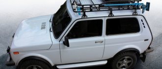
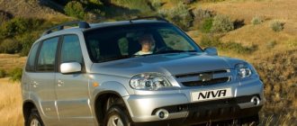
By installing a towbar on a Chevrolet Niva, the motorist has the opportunity to transport trailers and other vehicles. The manufacturing plant of this model intends to make similar modifications to the design of the car, therefore it equips the car with standard places for attaching the trailer hitch. Installing a towing hitch has some nuances.
Installing a towbar Chevrolet Niva station wagon 2002-
The installation process of the towbar in photographs:
First you need to purchase a towbar. Choose a tow bar for your vehicle here. I have never seen a car on which you can install a towbar so quickly, within 10 minutes. Here, of course, we must pay tribute to AvtoVAZ. The standard body configuration already includes threaded holes for attaching a towbar, but they are sealed with tape. (In the photo, the taped areas are indicated by arrows).
You need to tear off the adhesive tape, place the towbar against the side members and the apron and tighten it with the mounting bolts (supplied), after lubricating them with graphite lubricant. That's it, the tow bar is in place!
Now you need to install the outlet. This will take much more time than installing a tow bar. For this:
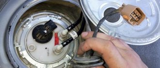
- Disassemble the socket: remove the stopper from engagement with the body
- turn the contact pad counterclockwise
Near the area with the car body number, under the vibration-insulating layer, find a plug (in the photo, the area with the number and the plug are indicated by arrows).
Take it off. Make a hole in it with a punch.
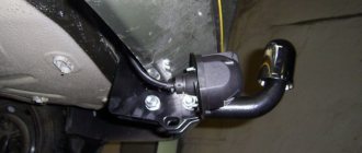
Disassemble the right rear light casing (attached to two pistons). Disconnect the connector from it. Connect the towbar wiring harness.
Remove the standard wiring for the right rear light from the corrugated tube. Strip the necessary wires, about 2-3 cm, and tin them with tin.
The procedure for connecting the towbar terminals to the rear lights is as follows:
| Towbar socket | Right light wire color | Left light wire color | |
| contact No. 1 | left turn | —– | blue-black |
| contact No. 3 | weight | to the body | —– |
| contact No. 4 | right turn | blue | —– |
| contact No. 6 | stop signal | red | —– |
| contact No. 7 | dimensions | brown | —– |
Insulate solder joints. Connect both strands together and put a corrugated tube on them. Wrap it with electrical tape in two or three places.
Use the tow bar strictly for its intended purpose :))
The towbar installation instructions/diagram are for informational purposes only. Since towbars from all manufacturers are different. AutoDels.com.ua is not responsible for any consequences when installing a tow bar. We recommend installing towbars only from specialists!
To make an appointment for the installation of a towed Chevrolet Niva, please contact our specialized service station on the street. Kozatskaya, 126 by phone,
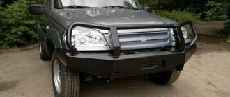
Bumper towing options
Before purchasing a towbar for a Chevrolet Niva, you need to familiarize yourself with the manufacturing companies and the varieties of this part.
Among the companies that occupy leading positions in the production of towbars, it is worth highlighting such as “Bosol”, “Auto-Hack”, “Baltex”. Experienced motorists and specialists recommend choosing trailer hitches manufactured by these companies. The devices are characterized by high reliability and high-quality materials.
Towbars for Chevrolet Niva are divided according to the design of the product into:
- Removable.
Easy to install and dismantle. Mounted with 2 or 4 bolts, which are easy to remove. You can often find models with a removable ball on sale.
- Fixed.
They are a one-piece design. Installed on a reinforced car bumper. They are welded to the side members or attached to massive bolts.
- Quick release.
Often equipped with a folding mechanism. The ball is removed and stored separately from the trailer hitch. Used for transporting light loads in a trailer.
On the old-style Niva there are no standard mounting points for the tow bar. Experts do not recommend making special holes for mounting the trailer hitch yourself. In addition, it is impossible to find models of towbars for such cars on sale, and homemade towing devices do not have the proper quality.
After selecting a suitable towbar, we proceed to install the trailer hitch on the vehicle ourselves.
Making your own tow bar
Despite the sale of ready-made towbars, motorists independently manufacture trailer hitches for the Niva. To design a product yourself you will need:
The quality of a homemade trailer hitch will be an order of magnitude worse than a serial one. In addition, there will be significant problems with registering a homemade part with the traffic police. You also need to take care of proper installation. Otherwise, using the towbar may damage the rear of the vehicle.
Niva is an off-road passenger car. The vehicle is used for trips out of town, fishing and hunting trips. The car also often acts as a tug for stuck vehicles. By installing a towbar, you will be able to fully enjoy the operation of your car.
Source
Electrical connection
An electrical connection is necessary for the operation of additional lighting on the trailer. For this purpose, a 7-pin socket is used, which is supplied with the towbar.
The socket connection diagram is in the towbar instructions and looks like this:
- Left turn signal.
- Fog lamp.
- Weight.
- Right turn signal.
- Reverse.
- Brake signal.
- Parking lights.
Connecting the socket to the wiring is carried out according to the following algorithm:
- The rear headlight is removed and the insulation on its wiring is stripped.
- The wires are soldered in accordance with the pinout diagram.
- The places where the wires are inserted are wrapped with electrical tape.
- The headlight is installed in place.
After completing the work on connecting the socket, check the functionality of the trailer lights.
How to connect the towbar socket?
To correctly connect a car trailer and a towbar fork with 7 or 13 connectors, you need to figure out what scheme you will use to connect. Connecting a towbar at home is carried out in accordance with one of two schemes - standard or universal. The standard option of connecting a smart socket with 13 or 7 connectors to the electrical wiring will be relevant if certain connectors are located on the device and the car trailer. Thanks to the contacts of the connectors, a connection is possible, then the car enthusiast can carry out all the work in the absence of a trailer connection diagram.
Designation of connectors in the socket for mounting towbar wiring
The essence of the action will be to correctly connect the contacts of a smart socket with 7 or 13 connectors with a socket. Often the pinout of the towbar socket and its approval are indicated in the service book for the car. But if, when connecting connectors of a smart socket with 7 or 13 contacts, for proper coordination with the trailer, it is necessary to make changes to the electrical wiring diagram, then this method will not be relevant. Car enthusiasts have to use a universal method, so we are ready to help you understand each of them.
Standard method
Most old domestic cars do not have a control and coordination unit. A car enthusiast can connect a 7- or 13-pin smart socket to an electrical system using existing wiring. In this case, a person saves himself from the need to use any splitters. That is, in essence, connecting a towbar comes down to connecting the wiring to the car’s electrical system so that the optics on the trailer work correctly.
Standard towbar installation diagram
In this case, the first thing you should do is study the diagram for connecting a smart socket with 7 or 13 contacts to the matching unit. The purchased socket is connected so that the contacts are connected to the rear optics harness block of the car. The appropriate connectors are used for this.
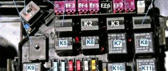
Pin layout in ABS and EBS sockets
No special knowledge is required to connect this type. To successfully implement the plan, it is necessary to pinout the semi-trailer connector.
Pin connectors ABS and EBS:
- The constant “+” at number 30 is responsible for the functionality of the ABS electric valves.
- When the ignition is turned on, “+” under number 15 takes power from the corresponding relay, which is located on the ABS electronic unit.
- Weight for output – 2.
- Weight 1.
- ABS system malfunction warning light.
- Buses CANH and CANL (only when connected to EBS).
The detailed pinout of the semi-trailer socket for each type of transport is below.
For tractor and trailer
Pin for installing ABS and EBS has the following wire colors:
- Dark red.
- Black, less often – gray.
- Bright yellow.
- Brown.
- Pure white.
- White with a light green stripe (in the case of EBS).
- White with brown stripe (EBS only).
Detailed information is visible in the video:
For semi-trailer
In case of connecting the ABS connector, the semi-trailer cable pinout is as follows:
- Dark red color.
- White and red.
- Brown with a blue stripe.
- Dark brown.
- Yellow with a blue stripe.
For VOLVO truck
When connecting ABS and EBS connectors on these car brands, there is a pinout of the following color:
- Red with a cross section of 6 mm²/4 mm².
- Light grey.
- Cloudy white.
- White, the cross-section of which is 6 mm²/4 mm².
- Brown.
- Pink.
- Purple.
For IVECO truck
When connecting to tractors of this brand, the semi-trailer transfer pinout has the following color:
- Red with a cross section of 4 mm².
- Green with a cross section of 1 mm².
- Brown with a cross section of 1 mm².
- Brown with a cross section of 4 mm².
- Purple with a section.
- White-brown with a cross-section of 2.5 mm².
- White-green with a cross-section of 2.5 mm².
Connecting the socket is clearly shown in the video:
What is a towbar and what is it for?
The presence of this element on the car will allow you to additionally attach a trailer to it . However, its functions are not limited to this. Thanks to the presence of such equipment, it is possible to tow vehicles with a rigid hitch.
Since the Niva is a universal SUV, and most of these vehicles are constantly used by village residents, having a towbar on the car, which will allow you to additionally transport a trailer with various loads or tow small equipment, is simply necessary. also allows you to protect the bumper and exhaust system from damage , taking on the full force of the impact when hitting a bump.
We conclude : with a tow bar, the versatility of an all-wheel drive car increases significantly. Therefore, it is very important to correctly install it yourself.
The design of this element is not complicated , but certain nuances still arise during its installation on a vehicle.
The design of a towbar can be described as follows : a base made of durable metal, which is attached to the rear of the car body with bolts. At the end of the base there is a ball that provides coupling to the trailer. A special socket is provided to connect the trailer to the vehicle's on-board network. Its pinout is not complicated, so not only an electrician, but also an ordinary motorist can connect the socket independently.
Types of Truck Lighting Sockets
Often, all new tractors are equipped with two lighting connectors - S and N types. Each of them is responsible for a specific function.
More details about them:
- Type N is designed for wiring brake lights and indicators from the truck to the trailer. For example, a DAF tractor unit connects the front fog lights this way.
- Type S is used to transmit power to reversing lights, as well as fog lights. For example, a Renault truck tractor has this type of connection.
Their appearance is often no different, but sometimes they can have different colors, for example:
Despite their similarity, they have specific wiring:
- N is equipped with contacts of the same thickness, only the ground connector has a larger diameter.
- As for S, its mass resembles the shape of a tube.
In addition to the above sockets, almost every Schmitz, MaZ, DAF or KAMAZ tractor has a 15-pole lighting system, as well as ABS and EBS. The Ford truck tractor is a little different.
Types of lighting sockets are presented in the following video: