The main function of a tachometer in a car is to determine the correct gear, which has a positive effect on the life of the engine. Most cars have an analog tachometer built into them during assembly. The driver looks at the arrow approaching the red line and knows when to shift into a higher gear. Not all cars have the type of device that satisfies the owner, so you just need to figure out what they have and how to connect the tachometer.
- Types of tachometers
- How to connect a tachometer via the ECU
- Connection diagram for a tachometer on a gasoline engine
- How to connect a tachometer to a diesel engine
- How to check the tachometer for functionality
Did you know? The term “tachometer” comes from the Greek
τάχος - speed and μέτρον - measure.
Types of tachometers
There are two types of tachometers: digital and analog. The first looks like a small screen on which the driver can see all the data he needs while driving. The second one is simpler and looks like a board with arrows and values.
Remote
A remote tachometer is installed on the front panel of the car. For greater ease of placement, this device has a leg for mounting on the panel. Remote digital tachometers are good for monitoring idle speed. Their readings have fewer errors, so using such a device you can check the operation of a standard tachometer. In addition, their stylish appearance gives the car elegance.
Staff
The standard tachometer is built into the dashboard of the car. This device is more convenient, since it is easier for the driver to perceive the movement of one arrow, rather than several indicators while driving. A standard tachometer is more often used in cars, and manufacturers of electronic devices produce kits for self-equipping cars.
Important! Measuring instruments are produced according to the car brand. The readings from a non-native mechanism will be incorrect.
How to connect a tachometer via the ECU
If your car does not have a carburetor engine and the injector, the tachometer is not connected to the ignition. In this case, you need to connect the engine control unit to the controller. The connection diagram for the tachometer is simple: take the ground to the body (ground), connect the plus from the device to the ignition positive. The tachometer has two inputs: the first goes to the control unit, the second to the crankshaft position sensor. The device connected to the computer will read pulses directly from the control unit controller.
Connection diagram for a tachometer on a gasoline engine
Before installing a tachometer on a carburetor engine, read the instructions included with the device. If it is not there, install according to the following steps:
- Secure the mechanism in its place (the location is determined by the type of device).
- Connect the black wire to the ground (body) of the car.
- Connect the red wire to the ignition switch terminal, which supplies 12 W during operation of the ignition system.
- The third wire can be any color. Since the ignition system is contact and non-contact, we will consider where to connect the tachometer in both. With a contact system, the device is connected to the distributor breaker. In the second system - to the voltage switch.
If the car has a display backlight, the tachometer is connected to the terminal provided for this in the ignition switch.
We recommend: Cleaning the carburetor - choosing the fluid and washing it yourself
How to connect a tachometer to a diesel engine
Before connecting, let’s figure out what makes the tachometer on a diesel engine work. The operating principle of an electronic device is to read pulses sent by a terminal located in the generator.
Since the process is labor-intensive, it must be carried out in an inspection pit.
The first point of work is to dismantle the protective casing of the generator, try to avoid getting dirt. The second step is connecting the tachometer to the diesel generator. To do this, find the terminal marked “W” on the generator body and connect the device output to it.
Attention! It is imperative to close the contact coming from the oil pump. If this is not done, the tachometer may “lie”.
It happens that the terminal indicated above cannot be found. In this case, disassemble the generator. Connect one of the wires connecting the winding and the rectifier to the tachometer cable. Insulate the wires and reassemble the generator in reverse order. Installing a measuring device is not very difficult, but without any knowledge of how a diesel engine works, how a tachometer works on a diesel engine, without the slightest idea about car repair, it is better to turn to professionals.
How to check the tachometer for functionality
We figured out how to connect a tachometer to a diesel and carburetor engine. Now let's look at the reasons for device breakdowns. You notice problems in the operation of the measuring device, for example, an arrow jumping in different directions. There may be several reasons for the breakdown. If the engine runs for a long time, vibration will occur, which may damage the display. The next reason may be oxidation of the contact group of the electrical wiring, damage to its insulation or disconnection from the tips. These are all visible causes that need to be eliminated immediately. If the sensor itself is broken, it needs replacement. If self-diagnosis does not reveal the cause, you should contact a car repair shop.
Interesting! The tachometer was designed by American Curtis Widder in 1903.
.
We recommend: Central locking in a car - what is it, how it works, video
Subscribe to our feeds on social networks such as Facebook, Vkontakte, Instagram, Pinterest, Yandex Zen, Twitter and Telegram: all the most interesting automotive events collected in one place.
Why does the tachometer needle jump?
To find out why the tachometer needle twitches, you need to perform the following manipulations:
1. Find the “Check” lamp on the dashboard and check if it lights up. If not, then, most likely, the system diagnostics will not be able to determine the malfunction.
2. Check the electrical wiring by testing the voltage level on the wiring plus and minus, and also check the condition of the connections.
3. If other equipment or devices are not working correctly, it is imperative to check the weight, because this detail is often overlooked.
4. Check the condition of the distributor contacts and the capacitor on its cover, as it could have been broken during operation.
5. Also, you need to check the circuits in the ignition system.
6. If you have recently repaired or replaced the device, then you simply need to configure it. To do this, you need to adjust the position of the zero and the device itself, adjust the connection quality and make adjustments using the toggle switch on the back of the installation.
7. If the needle jumps when the engine reaches high speeds, the switch is broken and needs to be replaced.
Recommendations
Comments 31
The diagnostic connector should have a pin with the letter “T” for scanning (under the tachometer). I installed a dashboard with a tachometer on a gasoline Kaldina (which did not have one from the factory). I connected the wire to the diagnostic connector. It still works, although more than five years have passed. If the engine is diesel, then you need to connect it to the speed sensor in the fuel injection pump.
To the connector? Oh well. There are no brains, no connector, no sensor. Fully mechanical diesel. There are two wires going to it. Spark plugs and fuel shut-off valve. The rest does not affect engine operation.
I wrote that it was on gasoline. There the conclusion comes from the brain. And on a diesel engine, impulses to the tachometer are taken from the speed sensor (on the fuel injection pump). You can also take it from the generator (if there is no sensor in the fuel injection pump). But with the fuel injection pump it shows more accurately.
That's right. But the tidy doesn’t understand directly from the sensor, you need a brain
If it’s just a diesel engine (without an ECU), then it should work. Connect a tachometer (for example, from a VAZ-2106) to the speed sensor (in the fuel injection pump) and check the readings. Will it work or not? I changed the instrument panel on my minibus to a digital one (from Mark-2). I also got tired of connecting it. But then I figured it out. It took a little do some magic with the pinout. Put a divider by two (on the chip). Now everything works. Although initially the instrument panel was from a gasoline brand. But I have a diesel.
There is a different tachometer on the jig. The original instrumentation does not understand because the tachometer was only available on the gasoline version of these cars. What about the Sprinter and the Kaldino that didn’t have a diesel tachometer?
Well then, just install a separate tachometer. Or stuff a tachometer, for example from Zhiga, into the original dashboard.
If it’s just a diesel engine (without an ECU), then it should work. Connect a tachometer (for example, from a VAZ-2106) to the speed sensor (in the fuel injection pump) and check the readings. Will it work or not? I changed the instrument panel on my minibus to a digital one (from Mark-2). I also got tired of connecting it. But then I figured it out. It took a little do some magic with the pinout. Put a divider by two (on the chip). Now everything works. Although initially the instrument panel was from a gasoline brand. But I have a diesel.
And their operating principle is different. On a jig, the tachometer comes directly from the ignition coil, and is powered from it. And the fuel injection sensor only counts pulses. Power supply for the device separately
The tachometer on the Zhiga is not powered by the ignition coil. It only takes impulses from the coil. And the tachometer itself is powered by voltage from the instrument panel (its plus and minus). Therefore, it can be easily connected to the speed sensor on the injection pump. There are two wires going to the sensor. One of them is for ground, the second is for the tachometer input terminal. If it doesn’t work with a minus, then you can try giving a plus instead of a minus.
It will be useful: How to remove the dashboard of a VAZ 2112
If it’s just a diesel engine (without an ECU), then it should work. Connect a tachometer (for example, from a VAZ-2106) to the speed sensor (in the fuel injection pump) and check the readings. Will it work or not? I changed the instrument panel on my minibus to a digital one (from Mark-2). I also got tired of connecting it. But then I figured it out. It took a little do some magic with the pinout. Put a divider by two (on the chip). Now everything works. Although initially the instrument panel was from a gasoline brand. But I have a diesel.
But, as I understand it, you originally had a tachometer on the microphone? Everything is ready for installation. There's just some tinkering with the electrics and changing the sensor in the tank. And there is nothing here at all. Therefore, only a separate tachometer with its own sensor
Another homemade tachometer
In order to measure the number of revolutions, as we already know, counting the pulses of the breaker or the voltage from the spark plugs is used. The frequency of these pulses is linearly related to the motor speed. You can also try to organize an inductive coupling with such a circuit, which will be demonstrated in this device.
For 1500 rpm - 50 Hz. This makes it possible to easily calibrate the device by frequency. Pulses received from the third output of the microcircuit are fed to the dial indicator. In this circuit the author uses a milliammeter. The indicator will show the voltage in this network. Since the duration of the pulses at the output of the microcircuit is approximately the same, the voltage is proportional to the frequency with which sparks are formed.
Ignition system for gasoline engines
Control of engine ignition processes can be organized by several methods:
- Distributor with one ignition coil;
- Distributorless with a dual (triple, quadruple depending on the number of cylinders divided by 2) ignition coil;
- Individual (for each spark plug).
In all cases, the coil receives a powerful pulse with an amplitude of 12V from a breaker (for cars before the 90s), a transistor switch, or directly from the engine control unit. It is from this point that the signal to the tachometer should be taken.
Recommend: SWAP engine
ZenDen › Blog › Instructions for tachometer RL-HM032R for Sea PRO OTH 9.9 S
I bought you know where a tachometer for the PLM. The installation instructions are not complicated... but in the menu everything is not so simple, so I made a translation. Maybe someone will be interested.
Tachometer RL-HM032R PRODUCT USE
Tachometer RL-HM032R
I. Work stroke settings 1. Press MENU six times while the TOT indicator is on and the backlight is off to enter the work stroke control interface. The default setting is 1P1R 2. To enter the clock setting mode, press and hold MENU in the clock control mode until the default setting 1P1R starts flashing. Briefly pressing SET will select the mode. 3. Possible modes
1P1R 1 spark per revolution 6P1R 6 sparks per revolution 2P1R 2 sparks per revolution 3P2R 3 sparks per two revolutions 3P1R 3 sparks per revolution 5P2R 5 sparks per two revolutions 4P1R 4 sparks per revolution 1P2R 1 spark per 2 revolutions
II. Crankshaft rotation update rate (CR) 1. Press MENU seven times while the TOT indicator is on and the backlight is off to enter the crankshaft rotation update rate setting. Default refresh rate is 0.5 sec. 2. To enter the crankshaft rotation update rate mode, press and hold MENU until the original data starts flashing. Briefly pressing SET will select a mode. 3. Refresh rate can be set: 1.0 – update every second 0.5 – update every ½ second
III. Revolutions per minute 1. RPM – shows the current number of revolutions of the CV 2. When the PLM is turned off, the LCD display switches from RPM mode to TOT mode automatically, where the total number of engine hours is displayed.
Waterproof
IV. HF Maximum RPM 1. To view the maximum RPM, press MENU five times while the TOT indicator is on and the backlight is off. The maximum number of HF revolutions since the last launch of the PLM is displayed here. 2. Each time the PLM is turned off and on, the data is updated.
V. Warning about exceeding the permissible number of HF revolutions 1. To set a warning signal about exceeding the permissible number of HF revolutions, press MENU four times with the TOT indicator on and the backlight not working. By default, the overspeed alarm is set at 8500 rpm. 2. To set the maximum RPM number, press and hold MENU in number alert edit mode until the original data starts flashing. Briefly press SET to increase and MENU to decrease the permissible speed indicator. 3. If the set permissible revolutions are exceeded, the RPM and speed indicator will begin to flash. The indication will flash 5 times for 3 seconds, then stop flashing for 3 seconds, and so on cyclically.
VI. Hours display When the PLM is turned off, the LCD display shows the total number of engine hours.
Backlit
VII. Backlight Pressing MENU or SET once turns on the backlight, which turns off automatically.
VIII. PLM operating timer 1. With the backlight off and the TOT indicator on, press MENU twice. The operating time will be displayed. 2. Long press MENU in this mode will reset the timer.
IX. Display of service interval and its settings. 1. With the TOT indicator on and the backlight not working, press MENU three times to enter the SVC service interval setting mode, which counts down. 2. Long press MENU to enter SVC service interval editing mode. The data on the display will begin to flash. To increase, press SET to decrease MENU. 3. By default, the service interval is set to 20 m/h. Possible setting range 0-200 m/h. After setting the required value, the tachymeter will automatically switch to TOT mode, which means confirmation of the successful installation of the service interval. When the PLM reaches the set value, the display will start flashing. 4. To turn off the alert, press SET or MENU. 5. When the notification is turned off, the service interval timer will automatically begin counting down again with the previously specified range before maintenance. 6. If the interval is set to 0H, then the countdown to maintenance is disabled.
X. When the PLM stops and there is no action with the tachymeter for 10 seconds, the LCD display will automatically save all data and go into TOT mode (motor hours mode).
Equipment: Tachometer 1 pc. CR2032 battery 1 pc. Velcro tape for attaching to PLM - 1 set Plastic clamp 2 pcs.
We'll stage it today! I might take a video
Do-it-yourself tachometer installation: accessible instructions
A car enthusiast who cares about his car should have, among other devices, a tachometer, which helps to operate the car correctly. If there is no standard device, then it should be installed. The article describes their types and gives instructions on how to correctly connect the tachometer to a diesel engine and to a gasoline engine.
The tachometer informs you about the number of crankshaft revolutions, which helps you determine at what point it is best to change gears. This makes it possible to increase the service life of the power unit and operate it competently, since the power and traction characteristics of the engine depend on the crankshaft speed. In addition, it can be used to accurately adjust the carburetor and other important idle speed components.
This meter can be analog, which is a display with arrows and numbers. When the needle approaches the red line, the driver must shift to a higher gear. On the digital device, information for the driver is displayed on a small screen (video author – Armadil).
Conventionally, devices can be divided into two types:
- Regular ones. They are installed at the factory that manufactures the vehicle. They place it on the torpedo.
- Remote. They are an alternative option if a factory device is not available. Remote devices have more accurate readings, so they can be used to check the accuracy of standard readings. Sometimes they are installed as tuning.
The tachometer can be installed on both a gasoline engine and a diesel unit.
Connection to a gasoline engine
The connection of the device is different on an injection engine and with a carburetor. With the injector it is connected to the ECU controller. In this case, the “ground” is diverted to the body, and the positive wire must be connected to the positive ignition terminal.
The device has two outputs: one goes to the crankshaft position sensor, and the other goes to the ECU. Thus, it will read the number of revolutions from the controller of the control unit. Below is a diagram of connecting a tachometer with BSZ.
Below are instructions on how to connect an electronic tachometer to a gasoline power unit:
- First, depending on the type of device, you need to install it at the place where it will be located.
- Next, the installed tachometer should be connected. The negative wire is usually black and connected to ground.
- The red wire should be connected to the positive of the ignition switch, which is supplied with 12 V when the ignition system (SZ) is operating.
- The third wire can have any color - this is the input of the device. It is connected depending on the SZ. If the SZ is contact, then the device is connected to the distributor breaker; in the case of a non-contact SZ, it must be connected to a voltage switch.
- If the car is equipped with a backlight, the device must be connected to the car's size switch.
Connecting the device to a diesel engine
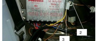
Diesel owners should know how to install a tachometer on a diesel engine, since its connection has nuances. To do this, you need to understand the principle of its operation. In the case of a gasoline power unit, it reads the pulses arriving at the ignition coil, and in the case of a diesel engine, from the “W” terminal of the generator.
It is better to install the device on a diesel engine by placing the car on an inspection hole or a lift. Connecting the electronic tachometer is carried out in stages. The first step is to remove the protective cover, avoiding contamination.
Next, on the generator you should find the terminal marked with the letter “W” and connect the wire from the tachometer to it. If you cannot find the terminal, you will have to disassemble the generator.
After disassembly, you need to connect one of the three wires that go from the winding to the built-in rectifier with a wire prepared in advance. The connection point must be insulated and the wire brought out. Next, the generator should be assembled in reverse order. The output wire from the generator must be connected to the meter.
For accurate readings, it is necessary to close the contact that comes from the oil pump.
Checking the tachometer functionality
Everything is clear with the installation of the tachometer, thanks to the instructions outlined above. It remains to find out the reasons for the meter malfunctions. Sometimes drivers can observe a situation when the arrow begins to twitch from side to side.
There are several possible reasons for the malfunction:
- When the motor operates for a long time, the resulting vibrations can damage the device;
- faults associated with wiring: tips may become detached, contacts may oxidize, and insulation may be damaged.
These damages can be identified by visual inspection and repaired. If the sensor is faulty, it must be replaced.
What types of tachometers are there?
Car inverter 12 220v - how to choose a converter
Mostly there are analog (in the form of a dial with an arrow) and electronic (display) tachometers. More exotic ones - made in the form of a running scale on gas-discharge lamps (often found on American-made cars), as well as mechanical ones - a legacy of the very first cars.
Mechanical
The very first tachometers installed on cars in the early and mid-twentieth century were devices connected directly to the engine crankshaft.
The principle of operation was quite simple: there was a gear on the crankshaft that meshed with a cable drive, which transmitted torque to a coil, which was an electromagnet of the device itself. The more revolutions, the greater the magnetic induction that occurs, the more the needle of the device deviates. Everything is very simple. However, the measurement error was quite high and could reach values of up to 500 rpm.
Analog
Further development led to the emergence of analog tachometers using a similar operating principle. The difference is that instead of being constantly driven by the crankshaft, the frequency of power supplied to the ignition coil is used to read the number of revolutions.
What it looks like in action. To create a spark on the spark plug, a short-term low voltage pulse is applied to the coil that converts low (12V) voltage to high (from 12,000 to 24,000V). The same pulse is supplied simultaneously to the electrical circuit of the analog tachometer and the electromagnet winding. The more pulses are supplied to the winding, the greater the induction force appears, and the greater the angle the arrow deflects.
It should be noted that the error of analog tachometers can range from 100 to 500 rpm.
Digital
Since digital electronic tachometers are increasingly replacing their analog counterparts, not to mention mechanical ones, we will dwell on them in more detail.
The basic principle of operation of a digital tachometer is to measure and count the number of pulses arriving at the primary winding of the ignition coil, or measure the time interval corresponding to these intervals and convert the received information into digital values displayed on the display.
Video - digital tachometer with many settings and Shift Light:
In addition to the fact that a digital tachometer operates on all of the above values, to improve measurement accuracy, the device also processes values coming from the idle speed sensor and, sometimes, the crankshaft sensor. The 1xbet working website has a fairly wide line: there are about 35 different sports. The painting is also impressive, and, of course, the largest number of events is associated with football. However, for other directions there is plenty to choose from. You should also pay attention to eSports events, since this area is only gaining popularity: there are more and more games, as well as events related to them. Placing bets with 1xbet is not only fun and comfortable, but also as profitable as possible. All data is summed up, and the resulting average value is practically a true indicator.
Since approximately half of the total number of cars (especially compact or small cars) are not equipped with a standard tachometer, electronics manufacturers offer installation kits for self-installation of an electronic tachometer.
A simple set represents, in fact, the display itself, often liquid crystal with a built-in board for processing incoming information and a set of wires for connecting to the standard terminals of the coil (the first cylinder with a distributed ignition system), as well as power.
More complex ones may contain additional idle speed sensors, as well as an external optocoupler. However, such kits are installed for a specific purpose - to gain complete control over engine speed. A simple kit is sufficient for everyday use.
For clarity, below is a typical wiring diagram for an electronic tachometer that receives information only from the ignition coil.
As described above, the tachometer receives the signal from contact K of the ignition coil, which receives low voltage pulses, power is supplied from terminal B of the ignition coil (constant +12V when the ignition is turned on), minus is the vehicle’s weight.
Another version of the tachometer connection diagram - using information from the controller (the “brains”) of the car is shown below.
In this case, to display the number of engine revolutions, information received from the crankshaft position sensor and processed by the controller is used.
How to install a tachometer yourself
Connection via ECU
The process of installing a tachometer on a car with a gasoline engine differs from installing this instrument on a car with a diesel engine. Based on this, the article will discuss both installation methods.
Installation of a tachometer on a vehicle with a gasoline internal combustion engine
With a contactless ignition system
If a tachometer connection diagram is attached to the device, it is strongly recommended that you study it in detail and make the connection in accordance with the accompanying documentation. If there is no diagram, installation of the device is carried out in several stages:
- The device, depending on the type, is fixed either to the appropriate seat on the dashboard or on its surface.
- The black wire is connected to the body (ground) of the vehicle.
- The red wire connects to the ignition switch terminal, which will supply 12V when the ignition is on.
- The third wire of the device can be painted in any color. It must be connected taking into account what ignition system is installed on the car. If the system is contact, the tachometer must be connected to the distributor breaker. With a contactless ignition system, the device is connected to a voltage switch.
- To provide backlighting for the display, if provided by the manufacturer, the device should be connected to the terminal provided for this purpose on the ignition switch.
How to connect with a contact ignition system
Installation of a tachometer on a vehicle with a diesel engine
The device should be connected to a generator, so it is best to install the tachometer on an inspection pit or overpass. Before starting work, the generator protection is dismantled. Next, on the generator you need to find the terminal with the Latin letter “w” and connect the tachometer output wire to it.
Tachometer rear panel diagram
The next step is to close the contact that comes from the oil pump. This action is performed to ensure that the tachometer gives reliable readings.
Diesel
It should be noted that sometimes it is not possible to find the generator terminal with the Latin letter “w”. In this case, you need to disassemble the generator, connect one of the three wires that connect the winding and the rectifier to the tachometer cable and insulate the connection well. After this, the generator is assembled in the reverse order.
Scheme for connecting a tachometer from Volga
In conclusion, it should be noted that installing a tachometer is not a very difficult job, however, it is strictly not recommended to start doing it without theoretical knowledge and some practical experience related to car repairs. Without firm confidence in your own capabilities, it is best to leave the car at the disposal of qualified workers at a specialized station who will be able to install a tachometer on your vehicle in the shortest possible time.
Testing, tachometer adjustment
If the car is equipped with a distributorless or individual ignition system, the tachometer can be connected to any coil. In this case, the readings of the engine rotation speed (rpm) will be inadequate, since an impulse is supplied to the trammel ignition every stroke, while the individual ignition is four times less likely. However, it is possible to calibrate the measuring scale in a new way.
At the first stage of testing, start the engine and check the performance of the system (arrow deflection at idle speed). As a rule, the speed in this mode is in the range of 800 – 1000 rpm.
Next, adjust the reading level. If the tachometer needle deviates slightly, you can connect an additional capacitor with a capacity of about 1 μF between the signal wire and the vehicle ground. On the contrary, if the arrow goes off scale, connect a variable resistance of about 1 kOhm to the open signal circuit and scale the signal.
The next stage is sea trials. With the engine running, the maximum speed is reached. The tachometer needle should not go into the red zone. Otherwise, the adjustment is carried out again. Before starting operation, check the reliability of connections and insulation again. And remember, additional equipment means new problems.
Tachometer for a two-stroke engine - applications and selection
An electronic tachometer for a two-stroke engine should be considered separately. One of the varieties of such a device is a waterproof version, used in motorcycles, scooters, snowmobiles and other vehicles with two-stroke engines. In practice, this is the same as a tachometer for a single-cylinder engine, which determines its service life, as well as the frequency of maintenance, such as valve adjustment, oil change, spark plugs, etc.
Installing such a device on the mechanism is very simple. There is no need for a separate battery thanks to the built-in rechargeable battery. The connection is made directly to the wire of one of the spark plugs. The resolution of such a device is 0.1 hours, it can count up to a maximum of 10 thousand hours, and then reset.
Tachometer dials vary in size. For example, a device with a diameter of 125 millimeters is most often used in sports cars, where the driver must constantly monitor the operating modes of the engine and especially the amount of its torque. When a certain number of revolutions is reached, a special flash lamp is activated, after which the gear shifts into the next gear. Such large tachometers take up a lot of space and partially block the view.
More convenient devices have slightly smaller dimensions and are already 95 mm. The most common size is 52 mm, which allows you to install the device anywhere on the panel of those cars where their own tachometer is not provided by the design.
Analog and digital tachometers
A homemade tachometer can be of two types:
- Analog.
- Digital.
The differences are clear from the names. The first convert the electronic signal and output it to an indication device - voltmeters, ammeters, LEDs. The latter convert the analog signal into a sequence of zeros and ones, which are easily recognized by microcontrollers. The latter work with such complex combinations, ultimately converting the original value into numbers on the display.
Analogue tachometer circuit.
Analog tachometers consist of the following main components:
- an electronic microcircuit that acts as an amplifier and analog signal converter;
- wiring connecting all elements of the tachometer;
- scales with a specific graduation, which is applied by simultaneously measuring the rotation speed with a reference tachometer (instead of a scale, LEDs mounted one behind the other can be used);
- an arrow indicating the current value of the desired value;
- an electromagnetic coil on which the axis for the arrow is located;
- a reading device - a breaker (this is often an inductive sensor).
Digital tachometer circuit.
Digital tachometers perform a similar function, but consist of different components:
- ADC having 8 bits;
- a central processor that performs the function of converting an analog signal into a sequence of 1s and 0s;
- LCD display to display the current value of a certain value;
- speed sensor - chopper, must be used either with an amplifier or with shunts, depending on the design;
- a special chip that allows you to reset the current values to zero;
- in cars, sensors for fluid temperature, cabin temperature, oil pressure, speed, and many others can be connected to the CPU.
In the “heart” of the microcircuit, with the help of a personal computer, a certain algorithm is laid according to which the work takes place. The processor calculates mathematical formulas that depend on what parameter needs to be measured. When monitoring one value, the algorithm will be the simplest.
But a digital tachometer in a car can also be used as a temperature, pressure, and speed recorder. The microcontroller has several inputs and outputs. Reading devices are connected to them via buffer cascades - converters and signal amplifiers. But it is worth noting that when introducing additional equipment into the tachometer design, it is necessary to take this into account in the algorithm and software of the microcontroller.
To make a homemade digital tachometer, you will need knowledge of a personal computer and a programming language. The ability to compose algorithms will also be useful. Therefore, it will be simpler to use conventional microcircuits that will amplify the breaker signal and output it to a strip of LEDs or a dial indicator. If there is a row of LEDs, consisting of 10 pieces for every thousand revolutions, then you can determine the current value with an accuracy of one hundred.
Malfunction of the tachometer
If signs of a malfunction appear, first you should pay attention to the general condition of the wiring. Very often, damage to the wires or lack of contact in them can cause the tachometer to break down.
Various minor defects in the form of traces of corrosion, minor cracks or loose fastenings are easy to eliminate, but if the damage is serious, the wiring will need to be replaced.
An equally pressing cause of failure is the installation of silicone ignition wires instead of the standard ones. This happens because the linear resistance of silicone wiring is very different from the resistance of factory wires. As a result, the shape of the current pulse changes. If you reduce the value of the resistor on the CP board, the fault will go away on its own.
As for digital tachometers, a popular cause of device malfunction is often the breakdown of a special digital screen that shows the current parameters of the car. To resume operation of the device, you will have to change the LED display.
It is also not necessary to rule out the breakdown of other parts; it is necessary to identify which element is broken and replace it with a new one.
Tachometer for a diesel engine - operating principle
You can see the tachometer readings directly while driving; it is located near the speedometer on the instrument panel. Various types of sensors are used to take readings; depending on this, the measurement method can be non-contact or contact. Tachometers are used not only in cars, but also in other devices where control over rotation speed is required.
However, it is in cars that this device has found its widest application. Not a single modern car can do without this device, which allows you to control the operation of the engine and change gears in a timely manner. All this helps to increase service life, contributes to fuel economy, and ensures traffic safety.
There are many varieties of these devices that are used in certain cases. They can be stationary and portable, as well as electric, magnetic induction, centrifugal and electronic. The very first tachometer was a centrifugal one, where the energy coming from the mechanism is transmitted through an axle. The impact on the arrow in each case is carried out differently, depending on the design of the device.
About company
Unfortunately, many domestic and imported cars lack one very important device - a tachometer. Based on the diagram published in. The device has a two-digit digital indicator showing the number of thousands and hundreds of revolutions per minute. The electronic tachometer is powered from the vehicle's on-board network and consumes a current of 0.45A. The electrical circuit diagram of the device is shown in the figure.
The operation of the control unit is described in detail in. The input driver and counter are assembled according to a standard circuit and have no special features, so they immediately begin to work. An intermediate memory on triggers has been introduced into the digital tachometer circuit to eliminate flickering of the indicator numbers during counting. The operating cycle time is set by selecting resistor R11, and the measurement time by selecting resistor R7. For a conventional four-stroke, four-cylinder automobile engine, an inductive sensor is used.
It consists of 50...70 turns of PEL 1 wire. One end of the sensor coil must be insulated, and the other must be connected to the tachometer input. Thus, the value of the number of revolutions corresponds to the pulse frequency Hz. But since the tachometer indicator should show 3 at this time. Therefore, the measurement time in this case is set to 0.3 s. The operating cycle time should be 10...20 times greater than 3...6 s.
Construction and details. All microcircuits of the series can be replaced with the corresponding series. All parts of the electronic tachometer, except for R1 and the digital indicator, are placed on a double-sided printed circuit board measuring 60x mm. The board is placed in a polystyrene case measuring 65xx35mm. DA1 is installed on a small finned radiator. About 5 V drops across resistor R1, which significantly facilitates the thermal regime of the stabilizer.
If all parts are in working order, the device starts working immediately. The setup is as follows: a signal with a frequency of Hz is supplied to the base VT5, and the readings of indicator 3 are set by selecting R7.
In conclusion, I would like to note that according to this scheme, my friends have assembled several electronic tachometers, differing only in design, and all of them have been working perfectly for several years on various cars. Shirokov B. Digital tachometer. Biryukov S. Digital devices on integrated circuits. For sound and light effects, you can assemble a simple circuit using three transistors.
It can be used anywhere: on a car, on a motorcycle, on a scooter…. Like many music lovers, I had a desire to install a subwoofer in a car. But an ordinary box-shaped subwoofer occupied almost a quarter of Oda’s already small trunk. In addition, I had experience working with fiberglass. Yes, I live in Ukraine in a godforsaken muhosransk, where people drink, eat and smoke. It’s more than a km to the area, besides, it’s a peak or an atemega for me to find just a piece of cake, but you won’t find such a fossil even in garbage dumps!!!
Everything is relative, of course, but most of the parts, including microcircuits and indicators, are found in old Soviet color TVs. This circuit does not contain scarce parts such as programmable microcontrollers, microwave elements, etc. Subscribe to our RSS feed to receive site news. Stay connected! Master Vintik.
Everything with your own hands! Here you will find free reference books and programs. The site contains simple diagrams, as well as tips for DIY beginners. Some of the repair schemes and methods were developed by the authors and friends of the site. The rest of the material is taken from open sources and is used for informational purposes only. If you have a question about a pattern or craft?
We are always happy to provide assistance in setting up circuits, making repairs, and making crafts! Repair for beginners, useful tips and crafts, free diagrams, programs.
Radio element parameters. Digital tachometer from available parts Added by: Vintik ,Date: Oct 12 Category: . Tags: . You can follow comments on this entry via RSS 2. You can leave a comment:. Charger from a computer power supply. Car chargers. Principle of operation.
Expanding the capabilities of a computer mouse! Latest comments Vintik: Good afternoon. This means that not only the trance burned out. The problem seems to be in Vintik: Depends on the TV model. Need a diagram. Usually to the fee kin Vladimir: good afternoon
Vlad: Thank you for your advice and attention to my problem! Just p Screw: If there is mechanical damage, then check the connections carefully. Screw: I didn’t have such a malfunction. To find out the video path and Screw: You need to look at the signal from the receiver output with an oscilloscope and Screw: Is the plate spinning?
Classification by operating principle
- Mechanical or electromechanical tachometers with direct drive. The revolutions are transmitted to the dial indicator through a flexible shaft, which, through a worm gear, receives rotation directly from the crankshaft or one of the transmission shafts. The operating principle of the indicator is based on the phenomenon of eddy current induction. The operation and design of a magnetic tachometer are extremely similar to the operating principle of a car speedometer. In modern cars, a similar tachometer design is not used.
- Electric machine. A distinctive feature is the connection to a generator. It is used primarily on diesel engines, but for the purpose of unification, a device of this type can also be used on gasoline engines.
- Electronic. The signal can be taken either from the ignition system or directly from the computer. Installed on gasoline and diesel internal combustion engines.
Design and principle of operation
Main components of electric machine and electronic tachometers:
- measuring unit, or signal converter. It can be based on elements of analog circuitry or built using special microcircuits;
- display unit with analogue or digital display of the number of revolutions;
- auxiliary elements.
The operation of electronic tachometers is based on the conversion of individual signals or pulses captured from the computer, ignition system or generator into a signal “understandable” for the display unit.
Connection diagram
When looking for the reason why the tachometer does not work, it is first of all important to understand the connection diagram and the type of signal. There are 3 typical connection schemes:
- to a contactless ignition system (the tachometer wire is connected to the primary circuit of the ignition coil). The operating principle is based on measuring the frequency of voltage surges in the primary circuit of the ignition system. Calculating the ignition angle is impossible without focusing on the number of crankshaft revolutions, therefore the sparking frequency directly depends on the crankshaft rotation speed. On 4-cylinder internal combustion engines, a full revolution of the crankshaft corresponds to 2 voltage pulses in the primary circuit. Accordingly, the higher the crankshaft rotation speed, the greater the frequency of voltage surges;
- connection to the contact ignition system. The operating principle and connection diagram are similar to the BSZ, but the design of the measuring unit will differ depending on the voltage of the input circuit;
- connection to the engine ECU. The principle of operation is still based on recording voltage pulses in the primary circuit of the ignition system, but the signal to the tachometer comes from the engine control unit;
- connection to the generator (the tachometer signal contact is connected to terminal W of the generator). The rotation of the generator pulley is carried out by a belt drive from the crankshaft, so the rotation speed of the generator rotor will always be proportional to the crankshaft speed. The change in the number of revolutions of the crankshaft can be calculated by constantly measuring the amount of EMF generated on the winding. According to its principle of operation, an electric machine tachometer resembles a regular one class=”aligncenter” width=”448″ height=”412″[/img]
Typical faults
If the mechanical tachometer on a car stops working, there is mechanical damage to any of the structural elements. A broken cable of a flexible shaft, wear of the worm gear elements, the appearance of backlashes, deformations - all these reasons can cause the engine speed indicator to fail.
It will be useful: How many liters of oil are in the automatic transmission of a BMW X5
What to pay attention to if the electronic tachometer does not work:
- integrity of electrical wiring. In this case, it is important to check not only the signal wire, but also the ground and power supply of the instrument panel;
- quality of contacts. The presence of oxides and loose contact inside the chips may well cause the tachometer to fail;
- the integrity of the elements of the measuring unit, which are located behind the protective glass inside the dashboard. Among mechanical damage to transistors, burnout of microcircuits, tracks or swelling of resistors, the most common reason for a non-working tachometer is a violation of solder integrity. For example, on the Mitsubishi Padjero II, the appearance of microcracks in the soldering areas of the tachometer elements is a generally recognized disease.
On vehicles with an alternator connection, a non-functioning tachometer may indicate a faulty alternator. In this case, the breakdown is accompanied by the lighting of the low battery charge indicator and the sporadic lighting of a “garland” of warning lights on the dashboard.
In some types of design, changes in the linear resistance of high-voltage wires can make adjustments to the accuracy of the engine speed indication.
How to find the cause of the problem yourself
In addition to a visual inspection, for DIY diagnostics you will need a universal measuring device. If you know how to use a multimeter, you can easily check the power supply, ground, and also test the signal wire for a break.
The power supply is checked in DC measurement mode, the measurement range is up to 20 V. “Minus” is constant, “plus” appears only after the ignition is turned on. Pulses on the signal wire should appear when the crankshaft rotates. To search for a break, the multimeter must be switched to resistance measurement mode - ohmmeter. Sometimes, to detect a bad contact, it is enough to move the connector or harness in which the signal wire of the speed indicator is laid.
Tachometer needle twitches
The problem of a twitching needle is best known to owners of the GAZ 3110 Volga. The problem occurs on cars manufactured before September 1999 and equipped with instrument cluster 38.3801 (JSC Avtopribor). Due to design defects, the natural operation of a car generator, in which the amount of charging current is regulated by an alternating voltage supply to the excitation winding, leads to the twitching of the needle.
The tachometer needle may twitch due to weakened tension of the alternator belt, but in most cases it is possible to repair the tachometer on the Volga by replacing the dashboard and modifying the connection diagram.
How to connect a tachometer?
- home
- >
- Articles
Our company has resumed its work. We have taken all measures to carry out safe work during the COVID19 epidemic.
Please note: equipment will not be accepted for repairs until June 1
Tachometer, i.e. A device that measures engine crankshaft rotation speed (rpm) is installed in any modern car model. The device is designed for proper operation of the engine, the traction and power characteristics of which significantly depend on the crankshaft speed. Even if your car does not have a tachometer installed, you can purchase an external tachometer and connect it yourself, both to a gasoline and diesel engine.
For example, such models of tachometers as: Diode tachometer + digital voltmeter, Tachometer + Voltmeter 86105 DGT, Tachometer + water t + voltmeter 998182, Tachometer 7788LED + water t + oil t + voltmeter + oil pressure + Boost
How to install a tachometer? The tachometer for a gasoline engine and a diesel engine are installed differently. First, let's look at how to connect a tachometer to a car with a gasoline engine.
To connect a tachometer to a gasoline engine, the tachometer diagram that comes with it will help you. If a tachometer connection diagram is not provided, then you are in luck, and the tachometer installation process will be very simple for you. To begin, secure the tachometer in the most convenient place for you. Next, deal with the wires coming from the tachometer. There are only three of them: a black tachometer wire, a red one, and, depending on the brand of the device, a wire of any color: for example, yellow.
The first, that is, the black one, should be connected to the car body, the red one should be connected to the terminal on the ignition switch. Connect the latter depending on the ignition circuit. It can be either contact or non-contact. In the first case, the tachometer is connected to the distributor breaker. And in the second to the voltage switch. Almost all tachometers are equipped with a backlit dial. It needs to be connected to the side lights of your car; to do this, find the corresponding terminal on the ignition switch.
Now let's look at how to connect a tachometer to a diesel engine. Most likely, you will need to go to the inspection hole and, having removed the protection from the generator, first of all clean it of dirt. On the generator coil you will see terminals, each of them is responsible for its own process. Next, find the terminal labeled “W” and connect the contact from the tachometer to it. The contact coming from the high pressure oil pump must be closed. This must be done in order to ensure that the correct tachometer readings correspond to reality. If this is not done, then after reaching 2500 rpm, a light on the dashboard will light up, which is responsible for the oil pressure in the system. If you were unable to find the terminal marked “W”, then you should find on the winding the output of the contacts to the built-in rectifier of the generator; there should be three of them. Choose one of them and solder the end of the tachometer cable to it. If you did everything correctly, the tachometer will work. After completing all the steps, screw on the generator cover. Be sure to ensure that the wire does not touch any moving parts.
Now you know everything about connecting a tachometer and can safely begin installing the tachometer.
But connecting the tachometer correctly is half the battle; when purchasing, be sure to find out whether the device you are purchasing is suitable for your car. The thing is that tachometers for gasoline and diesel engines count the number of pulses coming from the ignition coil or generator differently.
The principle of operation of the tachometer
Currently, tachometers are distinguished:
- Mechanical. A mechanical tachometer receives information about engine speed using a rotating cable mechanically connected to the engine crankshaft. Nowadays such devices are practically no longer used in cars;
- Electromechanical. The operating principle of electromechanical tachometers is based on the conversion of electrical impulses from sensors installed on the engine or from other electronic devices. These signals are converted into magnetic pulses that deflect the needle of the measuring device like a pointer voltmeter;
- Digital. Digital tachometers are used as part of modern computerized panels and are controlled by software and hardware. Self-installation of this type of tachometer is almost impossible.
Installation on a car with a carburetor
Before connecting the tachometer, it must be installed in the location chosen for it. This way you can immediately see how long of wire you will need. Then the negative cable is connected to ground. It is, as previously reported, black and white or completely charcoal.
Connect the brown or red wire to the ignition switch contact. Look at the diagram where the positive from the battery comes. If it is not there, then find it using a tester. This is done like this:
- set the multimeter to 20 V;
- Place the black probe on ground;
- Touch all the contacts in red one by one - the one you are looking for will have 12 volts.
The last posting is used to obtain data on the number of crankshaft revolutions 2105. Its color is not defined, each manufacturer uses its own. This cable in the contact ignition system goes to the distributor breaker. Otherwise, it is connected directly to the voltage switch. If the tachometer has its own backlight, then it is additionally connected to the car’s side lights circuit.
Connecting the device
The operating principle of an electronic tachometer is based on reading electrical impulses. In gasoline units, pulses are read and supplied in a certain amount to the ignition coil. As for the diesel engine, reading is carried out from a special terminal located in the generator housing.
To connect the tachometer to a diesel engine, it is advisable to carry out work on a lift or use an inspection pit. At the initial stage, it is necessary to remove the protection from the generator, avoiding dirt getting inside the device. The next step is a visual inspection of the generator coil, which has several terminals. The tachometer contact (input wire) should be connected to the terminal that is usually marked with the letter “W”.
Also, in some sources it is recommended to additionally implement the closure of the contact that comes from the oil pump. This operation is performed to ensure that the tachometer gives correct readings after installation, as well as to eliminate other problems. It is noted that otherwise, after the engine reaches a certain crankshaft speed, a warning light may falsely light up on the instrument panel, indicating a critically low engine oil pressure in the engine lubrication system.
If the terminal marked “W” is not initially present on the generator, then you will need to independently install a separate contact wire. The pre-prepared wire must be properly insulated. To facilitate access, the generator must be completely removed, as it will require partial disassembly. After disassembly, the wires (3 pieces) will become visible, going from the generator winding to the rectifier, which is also built into the device.
It is also worth considering that directly connecting the wire to the tachometer will lead to incorrect values. Additionally, you will need a divider board, which will make the speed readings correct.
|
Latest topics
- 111.970.330 thousand
easy rider - Yesterday, 23:38 - spoiler for 210 station wagon
easy rider - Yesterday, 22:39 - 2.3l 102.982 does not raise the speed above 1500-1800 at all!
minibear124 — Yesterday, 22:28 - I'll buy a 124 station wagon
anton076 - Yesterday, 20:51 - new original hood hinge for W116
sheremet - Yesterday, 19:14
- Andrew0709 (36)
- ChonG (34)
- macho (61)
- MAAX (14)
- pilot-MB123 (53)
All birthdays »
- https://scart-avto.ru/remont/rukovodstvo-kak-podklyuchit-tahometr-na-dizelnyy-i/
- https://krutimotor.ru/taxometr-na-dizel/
- https://oldmerin.net/board/index.php
Connecting a tachometer - diagram and tips
Every modern car is equipped with a device such as a tachometer. Information on how to connect a tachometer will be useful to owners of the first models of the VAZ family, as well as other cars that were not equipped with this important device from the factory.
Many motorists are well aware that using a tachometer makes it possible to increase the service life of the engine, since it is this device that helps determine the optimal moment to change gears. Although beginners often look at the tachometer, its installation helps every motorist. The tachometer is not only used while driving, it is also used to adjust the carburetor and other devices at idle.
The tachometer can be connected to any car, regardless of which power unit is located in the engine compartment - diesel or gasoline. Let's look at the methods for connecting a tachometer in more detail.
Installing a tachometer on a car with a gasoline engine
If the vehicle is equipped with an ignition system, the device itself must be installed first. Car enthusiasts often use an external tachometer. The tachometer connection diagram looks like this:
- negative wire (as a rule, it has black insulation) - to the ground of the machine;
- power wire (red) – corresponding terminal of the ignition switch;
- the wire connected to the measuring input of the device - to the ignition coil terminal, which is connected to the distributor breaker (this option is relevant for a car with a contact circuit, but if a contactless circuit is used, we connect the third wire of the tachometer to the voltage switch).
As a rule, tachometers are equipped with a backlight, which is recommended to be connected to the “dimensions” of the car (this must be done through a special terminal of the ignition switch).
Connecting a tachometer on a car with a diesel engine
Owners of cars equipped with a diesel engine should also know how to connect a tachometer. In such a situation, the test lead of the device is connected to the generator terminal, which is indicated by the symbol “W”.
If you could not find it, you need to disassemble the generator to get to the wires connecting the rectifier and the winding. We connect the tachometer wire to one of them. Don't forget to insulate everything well.
Then the generator is reassembled. At the end of our article, I would also like to advise you to take into account the features of devices when choosing them.
Thus, tachometers for diesel and gasoline engines use different methods for determining the number of incoming pulses, so before purchasing a particular device, do not forget to ask whether the tachometer will work correctly on your car.
Source: https://avtopub.com/podklyuchenie-tahometra-shema-i-sovetyi/