Operating principle
Essentially, a relay is an electromagnet. When control voltage is applied to the coil, the rod attracts the armature, thus switching the circuit.
There are three types of relays:
with normally closed contacts;- with normally open;
- throwing over.
When a control signal is applied to a device with normally closed connectors, they open; if there is no signal, they close. For relays with open connectors, the opposite is true. There is voltage on the winding, the terminals close, but when there is no voltage, it opens.
In flip-over models there are two sets of connectors, one normally closed and the other normally open. They have a common terminal. When current is applied to the winding, the contacts switch from one position to another.
Switching device design
An electrical relay is a device designed to be used as a switch. It can connect or disconnect an electrical circuit depending on the control signal coming to it. The line that is connected to the element is called controlled, and the one through which the command is sent to it is called control.
Relays are used to automate various operations. They successfully cope with managing various kinds of signals and protecting electrical equipment. They are used in security and heating systems, sound engineering, that is, wherever automatic switching of operating modes is necessary when any parameters change.
When searching and eliminating various faults in equipment, one of the repair stages is to test the switching element. This is done using a quantity meter. But before you test the relay for functionality with a multimeter, you should know how it works and understand the principle of its operation.
Principle of operation
A relay is an electromagnet consisting of a contact group, an armature and an inductor. All parts are installed on the base and placed in a closed housing. The elements are mounted as follows: an anchor (yoke) is placed on top of the core of the magnetic system. It is held in its initial position by a spring and is a movable L-shaped plate.
A group of plates with contacts is attached to the lower arm of the transmission, and the same number of contact bases is installed opposite them. Each lamella contact extends outward from the housing, forming the terminals of the device.
The principle of operation of an electronic device is the ability of an electromagnetic field to influence conductive objects. When voltage is applied to the terminals of the winding, current begins to flow through it. When its value reaches a certain value, two forces (electromotive and magnetic) arise in the winding, forcing the armature to press against the surface of the coil, overcoming the force of the spring.
At the same time, the arm with the attached contact plates also moves, arching them in such a way that they break contact with the connected group. As a result, electrical contact occurs. If connected to the terminals of these plates, the line is closed.
Depending on the design, the initial position can be either closed or open, so in the second type of relay, after applying voltage, the line will open. As soon as the signal of the required amplitude is removed from the terminals of the relay winding, the contacts of the device will return to their original state.
Types and characteristics
Electrical relay elements differ in the number of pins and shape, but their essence remains the same - connecting or disconnecting the load from the signal line. According to the type of physical processes that lead to recommutation, relays are divided into the following types:
- neutral - do not depend on the polarity of the signal supplied to the control terminals;
- polarized - in them the position of the contacts depends on the direction of the current;
- magnetoelectric - react only to direct current;
- ferrodynamic - their design uses ferromagnetic cores that enhance the magnetic flux;
- induction - based on the connection between a changing magnetic flux and an induced current in a conductor;
- thermal - react to heat that appears when current passes through the plates and changes their shape;
- electronic - they use the property of a pn junction to conduct current in only one direction (diode).
Devices are also divided according to the type of contacts, which can be of three types: normally closed, normally open and changeover. Like any electromechanical device, a relay is characterized by its technical parameters that determine the operation and purpose of the device. Of course, it will be impossible to check all the parameters of the relay with a multimeter, but with its help you can accurately determine the functionality of the switch. The main characteristics of the device include:
- winding voltage is the value of the signal amplitude at which the relay switches from one stable state of contact connection to another;
- switching current denotes the highest value of current that the relay can pass through without changing its parameters;
- the rated voltage is divided into values corresponding to alternating and constant signal levels, indicating the maximum potential difference, the appearance of which is permissible at the terminals connected to the load;
- operating frequency is the number of switchings that a device can perform per unit of time;
- wear resistance is determined by the mechanical reliability of contact groups, measured in cycles;
- The response time is characterized by the interval during which the position of the contact groups changes after the arrival of the control signal.
Functionality check
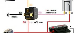
On the body of each relay there is a diagram with contact numbers and control voltage rating. A rectangle with pins 85 and 86 means a coil. Therefore, when measuring winding parameters, you need to connect to them. Other pins numbered 30, 87 and 87a (88) are the switching key for the external circuit.
It is convenient to use a digital multimeter as a tester for regulator relays and any other electromagnetic relay. This is because it can measure current, voltage and resistance.
Since the performance of the device depends primarily on the health of the winding, the test begins with measuring the coil resistance. Its values range from several tens of ohms to several hundred ohms.
To do this, switch the multimeter to resistance measurement mode. We connect measuring probes to pins 85, 86 and take readings. If the resistance is within normal limits, then you need to check the condition of the controlled outputs.
In a relay with normally closed contacts 30 and 87, when measuring the resistance between them, the multimeter should show 0 Ohm. With normally open pins 30 and 87 the resistance between them should be infinity. When the control voltage is applied to the coil terminals 85 and 86, everything should change exactly the opposite.
Sometimes only the actuation current is known, then the coil resistance is measured. After this, the multimeter readings are multiplied by the operating current, and the control action of the winding is obtained. Then, by applying the calculated voltage, you can check the contact group, as described above.
Only AC voltage can be applied to the AC relay coil.
After checking the relay, if there is a need and the ability to adjust the contacts, do so. Otherwise, replace the entire device. Its installation and removal must be carried out with the device's power turned off.
Preparing for the test
Before you begin diagnostics, it is important to determine the purpose of the pins on the element being tested. To do this, you can use the datasheet for the device, that is, the documentation issued by the manufacturer. It always describes the characteristics and diagram of the device.
Often, a diagram of the relay device is presented on the element itself. In this case, the control contacts are represented by points connected by an inductor, and the switching contacts are represented by straight lines with a dotted line, indicating their possible position. True, the power supply pins can also be drawn in the form of a rectangle with straight segments extending from the middle of its sides, controlled like a regular mechanical switch.
But even if there is no such circuit, you can try to evaluate the contacts visually (the control pins are made a little lighter in color). If the relay is soldered into the circuit, then it will be easy to trace the common bus and power traces on the board. In this case, contacts are often signed on the textolite, and from the schematic diagram it will be possible to determine their purpose.
To test a relay with a tester, you can use either a digital or an analogue device. But due to ease of use, it is better to give preference to the first. No setup or special preparation of the devices is required. The only thing you should pay attention to is the condition of the multimeter's battery. In a digital tester, the battery replacement icon should not light up on the screen, and in the analog version, when two test leads are short-circuited to each other, the arrow should be set opposite zero.
Application in car
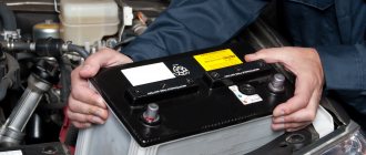
Most often motorists have to deal with switching devices. We are talking about the generator (starter) regulator relay. They remember it when the engine stops starting and it turns out that the battery is discharged. One of the reasons for this is a malfunction of the regulator.
On older cars, to maintain a constant voltage, a regulator was used, consisting of three devices - a voltage stabilizer, a current limiter and a reverse current relay. The regulator prevents the battery from overcharging, which prolongs its service life.
It can be built into the starter brush block or performed as a separate module. Its failure may or may not overcharge the battery. In the first case, streaks will be visible on the case, the electrolyte will begin to boil away, which will lead to a voltage drop below 12 volts. In the second, the values will initially be lower than acceptable. As a result, the engine will not start.
Reasons for failure of the relay regulator
In order to minimize the likelihood of repeated breakdowns in the future, you should familiarize yourself with the main reasons for device failure.
- Short circuit in any part of the electrical circuit, including interturn short circuit of the excitation winding.
- The regulator may also fail if the diodes break down or the rectifier bridge breaks down.
- Incorrect connection or reverse direction to the battery terminals.
- Penetration of moisture or large amounts of dust into the generator and/or the regulator itself (such cases are common during heavy rainfall or when washing the car).
- Mechanical damage to the working unit.
- Natural wear and tear, end of service life.
- Initially, the quality of the purchased product is questionable.
Checking the starter regulator
To check the starter regulator relay without removing it from the car, you can use a multimeter and test all the wires that go to it. To do this, they are first disconnected from the regulator. The multimeter is switched to resistance measurement mode, the disconnected wires are checked.
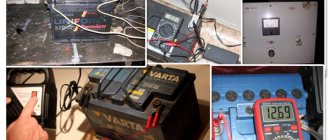
If everything is normal, then the conductors are returned to their place. The voltage at the battery terminals is measured with the engine off. The multimeter is switched to DC voltage measurement mode in the range from 0 to 20 Volts. The probes attach to the battery terminals. The device should show 12.2-12.7 V.
If 12 volts or lower, then it needs to be recharged.
Then the engine must be started and checked again with the same measurements. If the voltage is in the range of 13.2-14 V, then this is normal. We add engine speed to 2000 per minute and measure again. Normally, the multimeter should show between 13.6-14.2 V. We also add revolutions to 3500 per minute.
We take readings. They should not exceed 14.5 Volts. If the value does not change and remains 12.7 Volts, as when the engine is turned off, or even decreases, then the regulator relay is faulty. Therefore it needs to be replaced. If 14.5 Volts are exceeded, the regulator must also be changed.
Sometimes the question arises of how to test a relay with a multimeter if there is no access to the regulator. Then you need to remove it, and to check it you must have, in addition to the tester, a charger with a voltage regulator and a light bulb.
The following scheme is assembled from them. The charger is connected to the input terminals of the regulator, and the light bulb is connected to the output (thick) terminals. A multimeter monitors the voltage at the regulator input. By charging we change the voltage from 12 to 15 volts. The light should go out at 14.5 volts. If this does not happen, the regulator is faulty and must be replaced.
How to check the relay yourself
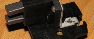
To check the relay, it must first be dismantled to gain access to all contacts. Below are typical circuit diagrams for connecting a 4- and 5-pin relay:
All relay contacts are labeled, the designations are located next to the “legs” themselves. But often power contacts can be identified by their yellowish tint, which makes them stand out from the rest.
To test a relay with 4 contacts, you need to apply a voltage of 12 V (for example, from a battery) to control contacts 85 and 86, and then measure the resistance between power terminals 30 and 87. The measurement is made using a multimeter in ohmmeter mode.
In the working relay, when voltage is applied, a click occurs, and the measured resistance becomes close to zero. If this is not the case, then the relay is faulty and needs to be measured.
What else can you read on our website?
To test a 5-pin relay, contacts 30 and 88 must be closed, and when voltage is applied to control contacts 85 and 86, the relay opens.
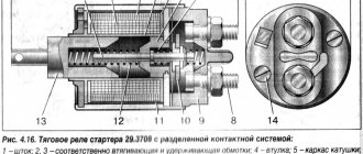
Checking the solenoid relay
When the battery is charged, but the engine does not start, you need to check the starter.
If the generator spins but the engine does not, then in such cases it is necessary to check the solenoid relay of the electric motor and the bendix. To do this, you need to remove the starter. After this, all contacts are cleaned, and the resistance of the relay winding is measured with a multimeter.
If the value is infinity, then the winding has burned out. In this case, it is necessary to rewind the coil or replace it. The device shows several tens of ohms, which means the winding is intact.
Then its performance is checked. The positive terminal of the battery is connected to the corresponding relay terminal using the cigarette lighter. And the minus is connected to the starter housing. A click should be heard, then the device is working properly, otherwise it needs to be disassembled and the mechanical part checked.
Common battery problems:
- short circuit of battery electrodes/plates;
- mechanical or chemical damage to the battery plates;
- violation of the tightness of battery cans - cracks in the battery case as a result of impacts or improper installation;
- chemical oxidation of the battery terminals. The main causes of these malfunctions are:
- gross violations of operating rules;
- expiration of the product's service life;
- various manufacturing defects.
Of course, the design of a generator is more complex than a battery. It is quite reasonable that there are many times more generator malfunctions, and their diagnosis is much more difficult.
It is very useful for a motorist to know the main causes of generator malfunctions, how to eliminate them, as well as preventive measures to prevent breakdowns.
All generators are divided into alternating and direct current generators. Modern passenger vehicles are equipped with alternating current generators with a built-in diode bridge (rectifier). The latter is necessary to convert current into direct current, on which the vehicle's electrical consumers operate. The rectifier, as a rule, is located in the cover or housing of the generator and is integral with the latter.
All electrical appliances of the car are designed for a strictly defined operating voltage range. As a rule, operating voltages are in the range of 13.8–14.7 V. Due to the fact that the generator is “tied” with a belt to the engine crankshaft, it will work differently depending on the speed and speed of the vehicle. It is for smoothing and regulating the output current that the relay-voltage regulator is designed, playing the role of a stabilizer and preventing both surges and dips in the operating voltage. Modern generators are equipped with built-in integrated voltage regulators, colloquially referred to as “chocolate” or “tablet”.
It is already clear that any generator is a rather complex unit, extremely important for any car.