Purpose of the voltage regulator relay
Regardless of experience and driving style, the car owner cannot ensure the same engine speed at different times. That is, the crankshaft of the internal combustion engine, which transmits torque to the generator, rotates at different speeds. Accordingly, the generator produces different voltages, which is extremely dangerous for the battery and other consumers of the on-board network.
Therefore, replacing the alternator regulator relay should be done when the battery is undercharged or overcharged, the light is on, the headlights are flashing and other interruptions in the power supply to the on-board network.
Interconnection of car current sources
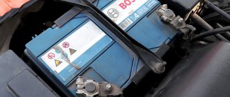
The vehicle contains at least two sources of electricity:
Both of these sources must be connected to the on-board network for the correct operation of the engine and other electricity consumers. If the generator breaks down, the battery will last for a maximum of 2 hours, and without the battery, the engine driving the generator rotor will not start.
There are exceptions - for example, due to the residual magnetization of the excitation winding, the standard GAZ-21 generator starts on its own, subject to constant operation of the machine. You can start a car “from a pusher” if it has a DC generator installed; with an AC device, such a trick is impossible.
Voltage regulator tasks
From a school physics course, every car enthusiast should remember the principle of operation of a generator:
In a simplified way, we can imagine that the magnitude of the voltage output from the generator is influenced by the value of the magnetic force and the speed of rotation of the field. The main problem of DC generators - burning and sticking of brushes when removing large currents from the armature - has been solved by switching to alternating current generators. The excitation current supplied to the rotor to excite magnetic induction is an order of magnitude lower, making it much easier to remove electricity from a stationary stator.
However, instead of terminals “–” and “+” constantly located in space, car manufacturers received a constant change in plus and minus. Recharging the battery with alternating current is not possible in principle, so it is first rectified with a diode bridge.
From these nuances the tasks solved by the generator relay flow smoothly:
Therefore, the voltage regulator is also called a charging relay, and the panel displays a warning light for the battery charging process. The design of alternating current generators includes a reverse current cut-off function by default.
What to do if the voltage relay fails?
It happens that the relay fails at the most inopportune moment, when you still have a drive home and the battery is not charging. The battery capacity in economical mode can ensure fairly long engine operation, which will allow you to get to the repair site without any problems. Below we will provide a list of recommendations that will help you drive, as they call it, “on battery power” and not stall.
- If the battery is overcharged, the relay must be disconnected from the circuit. To do this, the contact wires are removed from it and left hanging. In the case of the “ten”, it is enough to unplug the plug with the wire from the generator brush connector. Thus, battery charging is turned off, and further movement will no longer harm the battery.
- Many experts suggest going the other way - turning off the generator excitation winding . To do this, remove the corresponding fuse. However, this can be done if you know where the fuse is located.
- If the battery is weakly charged, then there is practically no reason to panic. To get to your destination, you need to maintain high speeds in order to, at least a little, bring the voltage value to the nominal value. to maintain the speed at 3000 rpm for a few seconds using the gas pedal This will prepare the battery for the next start.
- Avoid using music, power windows, headlights (especially high beams), and other electrical devices unless their use is absolutely necessary. This will save battery power well.
Types of regulator relays
Before you independently repair the voltage regulation device, you must take into account that there are several types of regulators:
Attention: Without modification of the circuit, the “plus” and “minus” voltage regulators are not interchangeable devices.
DC generator relay
Thus, the connection diagram for the voltage regulator when operating a DC generator is more complicated. Since in the parking mode of the car, when the internal combustion engine is turned off, it is necessary to disconnect the generator from the battery.
During diagnostics, the relay is checked to perform its three functions:
Any malfunction requires repair.
Alternator relay
Unlike the previous case, diagnosing the alternator regulator yourself is a little simpler. The design of the “automotive power station” already includes the function of cutting off power from the battery while parked. All that remains is to check the voltage at the excitation winding and at the output from the generator.
If the car has an alternating current generator, it is impossible to start it by accelerating down a hill. Since there is no residual magnetization on the exciting winding here by default.
Built-in and external regulators
It is important for a car enthusiast to know that they measure and begin to regulate the relay voltage at a specific location where they are installed. Therefore, built-in modifications act directly on the generator, while external modifications “do not know” about its presence in the machine.
For example, if a remote relay is connected to the ignition coil, its work will be aimed at regulating the voltage only in this section of the on-board network. Therefore, before you learn how to test a remote-type relay, you should make sure that it is connected correctly.
Control by “+” and “–”
In principle, the control circuits for “minus” and “plus” differ only in the connection diagram:
However, in the latter case, another wire will appear, since the voltage relay is an active type device. It requires individual nutrition, so “+” must be supplied separately.
Two-level
At the initial stage, mechanical two-level voltage regulators with a simple operating principle were installed in the machines:
Mechanical two-level relays were used in VAZ 21099 cars. The main disadvantage was working with increased wear of mechanical elements. Therefore, these devices have been replaced by electronic (contactless) voltage relays:
Complex wiring and insufficient voltage control have led to a decrease in demand for these devices.
Three-level
However, two-level regulators, in turn, also gave way to more advanced three-level and multi-level devices:
Relays with frequency modulation are considered more advanced - they do not have the usual resistances, but the frequency of operation of the electronic key is increased. Control is carried out by logical circuits.
Answers on questions
What is a relay regulator?
A voltage regulator relay (or simply a voltage relay) is a device designed to maintain the on-board network voltage received from the generator.
How does a relay voltage regulator work?
The regulator contains 3 elements: measuring, comparison and regulating. The measuring element senses the generator voltage and converts it into a signal, which is compared with the reference value in the comparison element. If the measured value differs from the reference value, a signal appears at the output of the measuring element, which activates the control element, which changes the current in the field winding so that the generator voltage returns to the specified limits.
Regulator relay diagnostics
Voltage regulator failures can be determined by indirect signs. First of all, this is incorrect battery charging:
However, it is preferable to diagnose with instruments - a voltmeter or tester. Any deviation from the maximum voltage value of 14.5 V (in some cars the on-board network is designed for 14.8 V) at high speeds or the minimum value of 12.8 V at low speeds becomes the reason for replacing/repairing the regulator relay.
Built-in
Most often, the voltage regulator is integrated into the generator brushes, so a level inspection of this unit is necessary:
In this case, instead of a voltmeter, you can use a lamp, which should light in the specified voltage range and go out when this characteristic increases above this value.
The wire that controls the tachometer (marked W only on relays for diesel engines) is tested with a multimeter in tester mode. It should have a resistance of about 10 ohms. If this value decreases, the wire is “broken” and should be replaced with a new one.
Remote
There are no differences in diagnostics for the remote relay, but it does not need to be removed from the generator housing. You can check the generator voltage regulator relay with the engine running, changing the speed from low to medium, then high. Simultaneously with the increase in speed, you need to turn on the high beams (at a minimum), the air conditioner, the monitor and other consumers (at a maximum).
Thus, if necessary, the vehicle owner can replace the standard voltage regulator relay with a more modern modification of a built-in or remote type. Diagnostics of performance is available on your own with a regular car lamp.
Source
How the relay works
This device on the VAZ-2107 (both carburetor and injector) is located in the same housing as the brush mechanism.
Its main purpose is to stabilize the voltage coming out of the generator. Not so long ago, relays made in the form of an electronic board were sold in stores. It had one drawback - a relatively short service life. Such devices could not be disassembled and were simply replaced with serviceable ones when they broke down.
Modern analogues are slightly smaller in size and use a semiconductor. The old type of relay can no longer be found. The new version is in no way inferior to it functionally and is also capable of reliably regulating voltage in the range from 13.2 volts to 14.8. Exceeding the last value when measured with a tester on the battery clearly indicates a breakdown of the relay.
Remote controller
This often happens to drivers. The brushes of the generating device burn out. The regulator is built in along with the brushes. We have to change everything together. And here’s some advice from experts: it’s better to install an external regulator than a built-in one. The models released recently have not been praised very much.
Okay, do you think I’ll install an external one, but how do I connect it? It turns out that there is a convenient scheme that makes it easy to carry out all this modernization.
Some important points:
This is what the connection diagram looks like
In the lower photo we see a diagram that shows the connection of the already built-in regulator relay.
It is suitable for connecting to “fives”, “sevens”, VAZ 2104, if the PG is installed from a VAZ “kopek”. As you can see, the remote-type regulator relay is connected via two terminals. Pin 15 goes to the fuse.
The second pin 67 is connected to the generator. The wire is connected to the brush chip.
Also, the remote-type relay must be connected to ground - any part of the body.
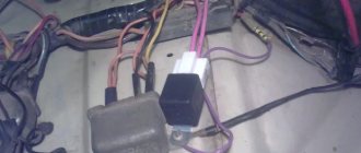
A relay is nothing more than a switch that serves to close and disconnect individual zones of an electrical circuit that occur at specific electrical values. A machine relay is otherwise called a load voltage switch, and this is 100 percent true. When the power supply unit, fan or starter consumes more current than necessary, the relay trips.
How to test a combined relay
For example, consider the regulator of a VAZ 2110 car. To check whether the relay is working, you need to assemble a circuit such as in the figure.
Relay regulator VAZ 2110 - 37.3701:
- 1 - battery;
- 2 — ground terminal of the voltage regulator;
- 3 - voltage regulator;
- 4 – terminal “Ш” of the regulator;
- 5 — output “B” of the regulator;
- 6 — control lamp;
- 7 — terminal “B” of the voltage regulator.
We recommend: How to install fog lights: connection diagram
When assembling such a circuit with a standard voltage of 12.7 Volts, the light bulb should simply glow.
If the regulator voltage is raised to 14-14.5 Volts, the light bulb should go out. If the light does not go out at such a high voltage, then the regulator is faulty.
GU or generator
The generator in any automotive electrical circuit performs the dominant functions. The normal functioning and operation of the machine depends on it. Reliable PG is installed in all foreign cars and models of the domestic automobile industry.
For example, a GU is placed on the “six”, the charge of which satisfies the need for electricity of any standard component. If you do not overload the generating device of the “six”, then the car is capable of driving many, many more kilometers. However, it is important to carry out preventive procedures in a timely manner - monitor the belt tension and the condition of the brushes.
The GU is connected according to the classical scheme. Using the VAZ 2106 generator as an example, let’s consider its functioning. This GU is marked as G-221. It is an AC synchronous electric machine with ELMG excitation. A VB (rectifier) with 6 diodes is built inside the GU.
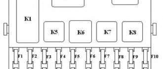
A simple and understandable scheme that does not require any subtleties or specific knowledge. On the “six” the PG is located on the engine on the right. It is attached to the tension bar with a nut and to the bracket with its claws.
As you can see, the diagram shows an external regulator. It is marked with the number 13. The generator is indicated with the number 2, the fuse box is indicated with the number 9.
Separately, I would like to consider the relay, which plays an important role in the “six” generator circuit. First of all, it serves to provide information to the driver about the charging status. As is known, it is created by a generating device.
The relay is made on the same principle as all devices that function according to the same properties. The connection is made to terminal 30 of the generator. A separate wire goes through the fuses to the 3Z (lock).
The action of the relay boils down to the following: as soon as the voltage of the BS decreases (falls below the 12-volt value), the relay contacts open, the indicator is activated, giving a sign to the driver.
To better understand the connection diagram, it is recommended that you also familiarize yourself with the principles of battery charging:
After the relay is activated or after the normal voltage value has been reached in the BS, the GU begins to generate current with the required value. The indicator lamp goes out, and the circuit starts working in factory mode. But when the total voltage drops, the current is not enough, and the contacts open, which leads to the discharge lamp burning.
The constant switching on of the charge indicator lamp indicates that the gene is not working properly. This happens for various reasons. First, you should check the fuses: if they are active, then both relays deserve attention: the regulator and the charger. If they are also in order, then faults must be looked for in the generating device itself.
Before proceeding with replacing the relay, it is recommended to carefully check the functioning of the regulator. The car starts, the speed is kept within the range of 2500-3000 rpm. After this, you need to turn off all current consumers, except the ignition. Then you need to measure the voltage at the battery terminals.
Charging may disappear in the following cases:
Thus, installing an external relay-regulator instead of a built-in one will bring a lot of benefits. The fact is that modern charging systems have much more power. Thus, modern memory systems are much more complex than old-style systems.
Source
The most common causes of breakdown
- Short circuit of the diode bridge or generator brushes. The result is a shutdown of the generator or a transition to uncontrolled voltage.
- Stabilization voltage shift. In this case, the stability of the voltage is maintained, but it is constantly either low or high.
- Oxidation or burnt contacts.
- Changing the size of the gap between the contacts.
- Relaxation of spring tension.
- Problems with the windings - breaks or short circuits.
We recommend: All about the oil in the gearbox of a Gazelle car
Breakdowns can be identified at an early stage - to do this, pay attention to the ratio of fuel consumption to the efficiency of the car. If the car consumes much more fuel than necessary, but performs worse, most likely the problem is in the regulator. A sure sign is the strength of the headlights at night. If, when driving at night, you notice that the intensity of the side lights and instruments has decreased significantly, it’s time to check the regulator.
How to connect a relay regulator to a car generator
How to connect a relay regulator to a generator
A built-in or remote regulator is one of the main components of the generator, ensuring stable operation of the entire vehicle power supply system. In some cases, it is useful to install an external regulator if overcharging or other difficulties are observed. Learn how to properly connect remote-type relays.
How to quickly and easily check the voltage regulator
Take a multimeter or voltmeter and measure the voltage at the battery terminals. The check is done in the following order:
- Put the device in voltage measurement mode at up to 20 V.
- Start the internal combustion engine.
- At idle speed, measure the voltage at the battery terminals. In XX mode, engine speed is from 1000 to 1500 rpm. If the generator and voltage regulator are working properly, then the voltmeter should show a voltage of 13.4 to 14 Volts.
- Raise engine speed to 2000-2500 rpm. Now the voltage value with the generator and relay working properly, the multimeter (voltmeter, tester) should show a voltage from 13.6 to 14.2 V.
- Next, step on the gas and increase the engine speed to 3500 rpm. The voltage of working devices should be no more than 14.5 Volts.
The minimum permissible voltage that a working generator and voltage regulator should produce is 12 Volts. And the maximum is 14.5 Volts. If the device shows a voltage value less than 12 V or more than 14.5 V, then the voltage regulator must be changed.
In new cars, mainly the relay is combined with a generator. This helps avoid pulling separate wires and saves space.

