The principle of operation of the nozzle
Rice. An example of the design of injectors for distributed (a) and central (mono) injection systems (b): 1 - fuel filter, 2 - o-rings, 3 - locking element, 4 - seat, 5 - spring, 6 - winding, 7 - housing, 8 - electrical connector
The design of an electric nozzle may be different (examples of designs are shown in the figure), but the operating principle is the same for all types of nozzles.
An injector is a container of fuel of a certain shape. On the one hand, fuel under pressure comes from the fuel line through the filter mesh, and on the other hand, in an atomized state, it enters the working area of the ENGINE if voltage is applied to the injector solar valve.
- MONO injection - one nozzle (usually in-line engine up to 4 cylinders)
- DOUBLE MONO injection - two nozzles operating on two halves of a usually 6-cylinder, V-shaped engine
- DISTRIBUTED injection - one nozzle per cylinder, the working part is located in the intake manifold
- DIRECT injection - one nozzle per cylinder, the working part is located inside the cylinder
- STARTING - one per engine, the working part is located in the intake manifold
Injectors are available in LOW ohms (from 1 to 7 ohms) and HIGH ohms (from 14 to 17 ohms). Low-resistance injectors are controlled by reduced voltage or there are additional resistances in the control circuits (5-8 Ohms). A fragment of the circuit with additional resistances (152) is shown in the figure.
Rice. Fragment of the control system diagram and photo of the resistance unit.
Rice. The shape of the sprayed fuel plume is different.
An oscillogram showing the pulse waveform of an injector with port injection (PFI) and sequential injection (SFI) systems that use a switchable saturation transistor drive is shown nearby and labeled A. The injector solenoids are turned on by the engine control module. The voltage drops sharply when the valve is open and then rises sharply when the voltage is turned off (due to the inductance of the solenoid). The pulse width varies depending on the engine load.
An oscillogram showing the pulse shape of a single injection injector (TBI). Such systems use peak current and synchronization current generators to turn the injectors on and off. The injector solenoid valves are activated when there is high current supplied from the engine control module.
Once triggered, the current decreases and keeps the valve open. There is a sharp drop in voltage when the valve first opens, and then a sharp increase in voltage when the current driver produces a lower synchronization current than the high turn-on current. When the solenoid is turned off (after a period of synchronization), a voltage amplitude is created due to the inductance of the solenoid coil (circuit B).
Some peak and sync current drivers produce rapid voltage switching during the sync period due to low injector solenoid winding resistance (diagram C).
Rice. Multipoint fuel injection nozzle.
An example is the oscillogram of the injector of the FORD Sierra 1.6i, EEC 4 car given below.
Rice. Injector oscillogram
Below are diagrams for connecting injectors for simultaneous, group and phased fuel injection.
With the simultaneous and group method, all injectors connected in parallel inject fuel at the same time, and half of the full portion of fuel is injected in one crankshaft revolution.
This method of connecting injectors was used on vehicles produced in the 80s - early 90s.
Modern engine control systems use sequential or phased fuel injection. This control method allows you to link the injection moment with the opening moment of the intake valve in a specific cylinder and change the amount of fuel supplied to the cylinder.
Rice. Injector connection diagrams for simultaneous, group and phased fuel injection
The following designations are used in the diagrams: 1,2,3,4 - injectors, 5 - engine ECU.
The injectors of direct fuel injection systems are different from the injectors used on intake manifold fuel injection systems. The injector nozzle is located directly in the combustion chamber and experiences high temperature and high pressure loads. The direct injection injector is longer because... it is necessary to go through the thickness of the block head. The fuel pressure is significantly higher than in conventional injection systems and the spray pattern has its own characteristics for each engine. These features of direct injection systems can be applied to gasoline and diesel engines. The figure shows the injector and its oscillogram of the HDI CITROEN engine. The resistance of the injector solenoid winding is 0.3 - 1 Ohm.
Rice. Injector of the HDI direct injection system and an oscillogram taken in mode XX.
The use of piezocrystals in injectors
The piezoelectric effect is a change in the geometric dimensions of certain crystals when an electrical voltage is applied to them. The operating principle is similar to that of an electro-hydraulic injector, but a cylindrical piezo crystal is used to activate the valve system. It converts the electrical signal into mechanical movement of parts.
Piezo injectors are distinguished by very high speed, since the change in the size of a solid body is characterized by low inertia and significant forces developed at the moment of counteraction from powerful springs and high pressure in the fuel line. This quality of the devices made it possible to use them for multiple fuel injections within one cycle. You can supply small pilot portions of fuel to initiate combustion, cool the mixture or create turbulence, organize layer-by-layer ignition of ultra-lean mixtures, and inject several additional volumes in power modes. But the price of such devices is quite high. Their use is justified in the case of the most high-tech engines with record performance in terms of efficiency and reduction of harmful emissions.
Location
The STARTING injector is usually located in the intake manifold so that its wide spray of atomized fuel (up to 90 degrees) hits the area of the intake valves of all cylinders.
The MONO injection nozzle is located in place of a conventional carburetor and fuel is injected into the general volume of the intake manifold.
DISTRIBUTED injection injectors are located on the intake manifold in the area of the intake valves of each cylinder. If there are two intake valves, then the spray of atomized fuel consists of two parts, each of which is directed under one of the valves.
DIRECT injection nozzles are located in the cylinder head. The sprayer is located in the cylinder and has a narrow slot that forms a torch directed at an angle to the piston bottom.
One of the fundamental differences between direct fuel injection systems is that, depending on the engine operating mode, the fuel pressure is regulated within 80-130 atm. The control system controls both the moment of injection, which occurs during the suction stroke, and the portion of fuel, changing the pressure in the pipeline and the duration of opening of the nozzle.
Nozzle types
Today, nozzles are distinguished into three types: electromagnetic, electrohydraulic and piezoelectric.
Electromagnetic injectors
This type of injector is usually installed on a gasoline engine. Thus, this type has the simplest and most understandable operating mechanism, consisting of solenoid valves, and also has a spray system with other parts included in it.
Electromagnetic injectors
The mechanism of operation of this type of nozzle use is very simple. Voltage is supplied to the winding system, which thereby excites the valve, which occurs at a certain time, usually for this purpose a program is installed, thanks to which the operating principle occurs.
Tension is created in the desired field by pulling the needle weight out of the valve, in which case the nozzle is released. As a result of such actions, a certain amount of flammable substance is injected. As the voltage decreases, the needle begins to return to its original state.
Type hydraulic electronic
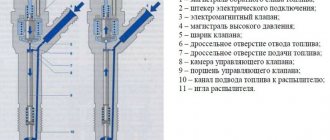
The mechanism of typical parts involves the application of a large amount of pressure in the flammable substance supply system. In the first version, the solenoid valves are closed, and the needle is mostly pressed against the seat of the place where the camera control system is located.
We recommend:
What is a rear stabilizer bar used for?
hydraulic electronic injectors
As a result, the signal that is supplied from this system to the mechanism begins to trigger the valve and the drain throttle opens. And this works due to the fact that fuel flows from the chamber system into the main drain mechanism. The throttle system of the intake mechanism begins to interfere with it so that the pressure temperature can burn out and the manifold in the intake system can quickly equalize its pressure.
As a result of this process, the pressure in the piston decreases and the force of the clamping system weakens, and since the pressure on the needle does not change, at that moment the same injection or, as one might say, the delivery of the car begins to occur.
Electric type
This type of nozzle use works through a mechanized hydraulic system. First, the needle is placed in the saddle by applying great pressure to it. When an electrical signal begins to arrive at the element of the piezoelectric mechanism, due to shocks on the piston system of the pusher, which thereby begins to put pressure on the piston mechanism of the switching valve. This thereby leads to the fact that the switching valve begins to open and, thanks to this, the fuel passes into the main drain system, the pressure at the top of the needle begins to decrease. Due to the fact that the temperature below does not change, the needle rises, in the process of which fuel is usually supplied to the system.
electromechanical injectors
Injector malfunctions
The injector winding resistance must correspond to the reference data. Typically, the injectors have a fine mesh at the inlet, which can become clogged with small particles of impurities or rust from the tank and fuel lines.
If the inlet mesh does not retain impurities, then passing through the locking element and the nozzle seat, these parts receive additional wear due to the abrasive properties of foreign particles. Gradually, the shape of the torch changes or disappears altogether and the injector pours fuel in a regular stream, which does not contribute to the correct operation of the engine.
Resin deposits gradually accumulate on the nozzle nozzle. Sometimes deposits are formed as a result of using a gas installation on the engine.
Benefits of using an injector
The service life of high-pressure injectors cannot be compared with the carburetor control model. The electronically controlled system has a number of advantages that are noticeable immediately after starting the engine.
- The metered injection system provides significant fuel savings;
- Increasing the power of the power unit and its dynamic performance;
- Huge operating life and no need for maintenance;
- Easy to start the power plant regardless of weather conditions;
- Less engine wear and smoother acceleration;
- Acceptable level of exhaust gases.
The efficiency of the injection engine is superior to previous generation systems and represents a finely tuned mechanism. Electronic control makes it possible to use low pressure injectors or the Common Rail system for the most accurate fuel supply. The carburetor rarely fails, and the absence of the need for periodic adjustments makes such a system easy to use.
The nozzle (injector) is the main element of the injection system.
Test method
Checking the fuel part of the injector must begin by connecting it to an autonomous installation, which can create working pressure at the inlet of the injector. In this case, fuel should not drip or flow from the injector. When the injector is briefly connected to a 12 V power supply (high-resistance injectors 14-17 ohms, low-resistance injectors - from 2 to 7 ohms through an additional resistance of 10-15 ohms), loud clicks of the shut-off valve, drawn in by the magnetic field of the solenoid, should be heard. If the injector “does not click,” then everything inside is probably clogged with rust. This nozzle goes on its “last journey.” If the initial checks give a positive result, we check the shape of the torch and the degree of fuel atomization, as well as the injector productivity per unit of time - this is usually 80 - 90 ml. in 30 seconds (50 - 60 ml for low-volume engines).
The device of a diesel electromagnetic injector.
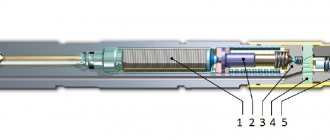
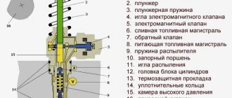
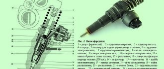
Diesel electromagnetic injectors consist of a housing in which valves, return springs, and channels are located. At the end of the nozzle there is a sprayer. The name and location of the nozzle elements can be seen in the picture below. The high pressure line is connected to the nozzle using a fitting. Moreover, a line is connected to the injector to drain excess fuel back. The main injector control element is an electromagnetic coil, which is connected to the vehicle's electrical wiring via a connector.
The nozzle nozzle is covered with a needle, which is tightly rubbed against the walls of the nozzle. The electromagnetic control piston, similar to the armature of a gasoline injector, moves due to the electromagnetic field of the coil. The control piston acts on the control chamber valve. As a result, the injector needle is raised not directly by the electromagnetic coil, but by the fuel, due to the pressure difference.
Advantages of the injector and its disadvantages
If there were no advantages to this system, injectors would not have become so widespread. Many people can challenge the reliability of the injector, because motorists often encounter problems and incurable diseases of the system. However, the technology has many more advantages that attract buyers and provide certain benefits during the trip.
| + Benefits | - Flaws |
| real reduction in fuel consumption - the injector can save money thanks to intelligent fuel supply control; | cleaning injectors - if you fill in low-quality gasoline or do not change fuel filters on time, the injectors will become clogged and stop spraying gasoline; |
| complete combustion of gasoline - with the correct settings, the injector ensures complete combustion of fuel and a certain intensity of travel; | flashing the “brains” in the required modes - on old machines it is sometimes possible to achieve incredible results from flashing, because technology is moving forward; |
| more expressive engine dynamics - the driver does not have to wait a long time for a reaction when pressing the gas pedal; | replacing the on-board computer with a more functional ECU version for your car model with suitable settings; |
| the ability to change the firmware - using a simple chip tuning procedure, you can completely change the car’s parameters; | regular change of filters, both air and fuel, to ensure normal operation of the injector; |
| manufacturability and modernity - a car with an injector often emits significantly less harmful substances into the atmosphere; | use of high-quality fuel in accordance with the standards prescribed by the manufacturer and a suitable octane number; |
| stable operation in any conditions - for good operation of the injector, manual control of the air damper is not required, the engine starts well in cold weather. | regular service, timely attention to certain shortcomings in the vehicle’s operation. |
Despite the fact that the injector is more expensive to maintain and more demanding on the quality of gasoline, its reliability and the ability to widely customize parameters are hundreds of steps ahead of the carburetor. In the end, over a certain mileage, two types of engines can cost the same, only the carburetor will need more attention, and the injector will need to be done once and for a long time.
And finally, we present to your attention a video for a more complete understanding of the principle of operation of the injector.
Source
