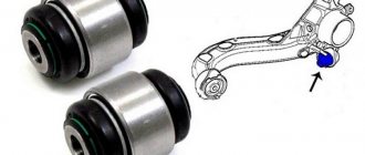
Car valve designs
Car valve heads (auto mechanics often call them poppets) can have different designs; they can be either rigid or elastic. The rigid head is highly durable, retains its shape and has high thermal conductivity. It also has higher wear resistance. The elastic head, in turn, is able to adapt to the shape of the saddle. Therefore, the elastic valve reliably seals the window, but overheats, and bends when fitting into the seat, when the valve adapts to its shape, can lead to its destruction. In the design of valves, a head is widely used, with a small cap protruding above the front surface. Such a valve has a fairly low weight, high strength and heat transfer, and a slightly higher price. Elastic heads are more common on intake valves, while rigid heads are more common on exhaust valves.
Cold air entering hot exhaust valves immediately after stopping the engine can cause serious damage to the valves. On engines equipped with exhaust manifold heads and/or straight-through mufflers, cold air has direct access to the exhaust valves. Sudden cooling may cause warping and/or cracking in the valve. In cold, windy weather, when the wind blows cold outside air directly into the exhaust system, such conditions are not uncommon. Counterflow mufflers with long exhaust pipes and a catalytic converter reduce the risk of this situation.
Repair and maintenance of intake manifolds
A modern intake manifold is a complex part. Breakdowns also happen to it. Let's look at typical ones.
Leakage problems
This is the first problem with intake systems, as well as many other components of the car. Vibrations, changes in humidity, pressure and temperature affect rubber (paranitic, etc.) seals, of which there are quite a few in complex intake systems. Additional air may enter the mixture, the so-called “suction”.
Air leaks in the intake manifold can significantly affect the dynamic performance of the engine as a whole. After the seal is restored, engine operation returns to normal.
Intake manifold contamination
The intake tract must be checked from time to time for deposits on the walls. A problem like this can have a significant impact on the dynamics of the car. The manifold becomes clogged especially often on engines with an exhaust gas recirculation system. In such cases, it is necessary to disassemble and clean the device with a special compound.
Deformations and mechanical damage to the housing
Plastic and aluminum are widely used for the production of collectors, and these materials, as is known, can be deformed due to exposure to high temperatures. Plastic cracks and dries out over time. Aluminum manifolds may burst due to vibrations.
Elements with severely damaged geometry must be replaced. Aluminum parts can be welded using argon arc welding.
Increased air temperature in the intake manifold
The causes of this problem may be:
- long-term idling in conditions of high air temperature (for example, in traffic jams);
- malfunctions of the cooling system and an increase in the overall engine temperature;
- poor ventilation of the engine compartment due to a clogged radiator;
- erroneous reading of the temperature sensor in the intake manifold;
- errors in the control unit firmware.
The solution is to check the cooling system components and diagnose electronic systems.
Popping sounds in the intake manifold
During ignition of the fuel in the engine cylinders, tightness conditions must be observed (both valves must be tightly closed). If the fuel is ignited with the intake valve open or slightly open, the fuel-air mixture may ignite in the manifold itself, resulting in a characteristic “popping” sound. Such breakdowns are quite dangerous - they can lead to significant damage.
The causes of the malfunction may be:
- violation of the ignition system;
- incorrectly configured gas distribution mechanism;
- violations of the tightness of the intake valves;
- problems with the formation of the air-fuel mixture.
In such cases, it is necessary to conduct a comprehensive engine diagnostics to identify the causes of the popping noises.
Let's consider the procedure for replacing the intake manifold gasket using the example of a 2021 Chevrolet Aveo engine.
1. Before starting work, turn off the power to the vehicle by removing the negative terminal of the battery.
2. Remove the windshield wiper arms (only necessary in the case of a specific engine).
3. Remove the plastic latch clamps 1 and screws 2, and then remove the air intake grille 3.
4. Drain the cooling system by unscrewing the radiator drain plug 4.
5. Remove the air duct of the air filter 5 by unscrewing the screws of the clamps 6.
6. Remove the forced crankcase ventilation tube 7.
7. Disconnect throttle communications 8-11, remove throttle 12 itself by unscrewing screws 13.
8. Disconnect brake booster pipe 14.
9. Unscrew screws 16,17 of the manifold bracket, remove bracket 15.
10. Remove the fuel injector guide, disconnect the throttle cooling hose 19, unscrew the manifold bolts 18.
11. Move manifold 20 to the side, carefully remove gasket 21.
12. Clean and degrease the seats for the new gasket and install it.
13. Reassemble the intake system components in the reverse order of disassembly.
Pay attention to the order and tightening force of the units being repaired. Tighten the threaded connections gradually in order from the center to the edge of the part, or crosswise
Proper operation of the intake manifold guarantees long-term engine operation. With minimal knowledge and a set of necessary tools, it is possible to carry out routine maintenance or minor repairs yourself. With complex parts and electronics, it is better to contact a service center.
Source
Types of intake manifolds
There are the following types of intake manifolds:
- steel;
- aluminum;
- plastic;
- with variable geometry;
- with exhaust gas control valves (EGR);
- turbocharged;
- with point fuel injection, etc.
On modern engines, manifolds with point fuel injection are quite common. In this modification, fuel is supplied using electromagnetic injectors installed in each of its pipe-channels.
Schematic diagram of an intake manifold with point fuel injection
The intake manifold, like the engine as a whole, operates productively within a certain speed range. The design and type of installed manifold depends on the layout of the cylinder block, on the target orientation of the engine and on design solutions in general.
All of the above collectors are divided into two groups:
- single-plane;
- two-plane.
A single-plane manifold supplies the air-fuel mixture through one common channel, while a multi-plane manifold initially divides the mixture flow into two streams.
Single plane manifold
Typically, engines with dual-plane manifolds produce more power at low and mid-range speeds between 2000-4000 rpm. At high levels, the power will be slightly lower due to the turbulence formed.
This is interesting: Features and advantages of cylinder head studs
Dual-plane manifold
A manifold with a common chamber without partitions reveals its potential at speeds of 5000 and above.
Installing an intake manifold of a different modification does not guarantee improved engine performance. Usually such parts are designed together with it.
What is ICE?
ICE (internal combustion engine) is one of the most popular types of engines. This is a heat engine in which fuel burns directly inside itself - in the inner chamber. No additional external media required.
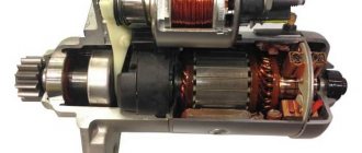
The internal combustion engine operates due to the physical effect of thermal expansion of gases. At the moment the mixture ignites, the combustible mixture increases in volume and energy is released.
Regardless of which internal combustion engine we are talking about - an internal combustion engine with spark ignition - an Otto engine (this is, first of all, injection and carburetor gasoline engines) or an internal combustion engine with compression ignition (diesel engine, diesel engine), the gas pressure force affects internal combustion engine piston. It is difficult to imagine most modern internal combustion engines without a piston. Including, even a combined internal combustion engine has it. Only in the latter, in addition to the piston, blade equipment (compressors, turbines) also helps the motor operate.
Gasoline and diesel piston internal combustion engines are engines that we actively encounter in any vehicle, including passenger cars, and internal combustion engines that operate not only due to the piston, but also due to the compressor, turbines are solutions without which it is difficult to imagine modern ships , diesel locomotives, automotive equipment, high-capacity dump trucks, i.e. transport where medium (> 5 kW) or high power (> 100 kW) engines are needed.
Without an internal combustion engine, it is impossible to imagine the movement of almost any transport (except electric) - cars, motorcycles, airplanes.
Despite the fact that technologies, including in the transport sector, are developing by leaps and bounds, humanity will continue to install internal combustion engines in cars for a long time. Even the Volkswagen concern, which, as is known, is preparing a large-scale program for the electrification of its engine range, is in no hurry to abandon the internal combustion engine. The information is open that cars with internal combustion engines will be produced not only in the next 5, but also 30 years. Yes, the development of new internal combustion engines at the concern is already approaching the final stage, but no one will curtail production. Current developments will continue to be used in the future. Some car manufacturing concerns are in no hurry to switch to electric motors. This can be justified both economically and technically. It is the internal combustion engine that is one of the most reliable and cheapest of all engines, and the constant improvement of internal combustion engine models allows us to talk about the confident progress of engineers, improving the performance characteristics of internal combustion engines and minimizing their negative impact on the atmosphere. Modern diesel internal combustion engines can reduce fuel consumption by 25-30%. Manufacturers of diesel internal combustion engines have been the best to achieve such a reduction in fuel consumption. But manufacturers of gasoline internal combustion engines are also actively surprising. Back in 2012, the American concern Transonic Combustion (developer of so-called supercritical fuel injection systems) impressed with its TSCiTM solution. Thanks to a new approach to the design of the fuel pump and injectors, the gasoline engine has become significantly more economical. Mazda is also making big bets on internal combustion engines.
He focuses on changing the design of the exhaust system. Thanks to it, the purging of gases is improved, the degree of their compression is increased, and, at the same time, the speed is reduced (by 15%)
And this means saving fuel consumption and reducing harmful emissions - despite the fact that we are talking about a gasoline engine and not a diesel engine.
avtoexperts.ru
A manifold is a technical device that is part of the internal combustion engine in a car. The main function of the manifold is to supply hot mixtures to the engine, as well as to drain them. Typically there are two manifolds - intake and exhaust.
The intake manifold collects the flows of combustible mixtures and gas into one common one and distributes them among the cylinders of the car engine, due to which the car moves. The combustible mixture must be distributed evenly, in which case the engine will operate without failures and with high performance. The intake manifold can also act as a holder for the throttle body, injectors, carburetor, and other engine components.
During operation, a vacuum is created in the intake manifold, which is used to control various systems in the car, such as power brakes, windshield wipers, cruise control, etc. This collector is also used to burn crankcase gases that are formed while the car is moving. The intake manifold was originally made of metal - aluminum or cast iron. However, plastic is used to produce modern collectors. Plastic, unlike metal, does not heat up, which improves the filling of the engine cylinders, and, as a result, increases engine power.
In turn, the exhaust manifold is part of the exhaust system of the vehicle; gas mixtures are exhausted through it, and internal combustion products are removed from the car. With the help of the exhaust manifold, the combustion chambers are also purged, which allows the engine cylinders to quickly fill with the next portion of the combustible mixture.
In the modern automotive industry, two types of exhaust manifolds are used - tubular and solid. The one-piece manifold is made of cast iron and has short channels combined into a common chamber. A one-piece manifold is not very efficient at removing exhaust gases, but it is affordable and easy to manufacture.
However, recently, cars have mostly been equipped with more efficient tubular manifolds. They are made of steel, and their design is created in such a way that the engine power is increased.
It is worth noting that on sports cars exhaust manifolds are often not installed, and each cylinder is attached to its own exhaust pipe, which allows the car to show higher speed qualities.
How it all works
Now let’s look at the principle of operation of an injection engine separately for each component. With the electronic part, in general, everything is simple. The sensors collect information about the speed of rotation of the crankshaft, air (entered into the cylinders, as well as its residual part in the exhaust gases), throttle position (connected to the accelerator pedal), and coolant temperature. The sensors constantly transmit this data to the electronic unit, due to which high accuracy of gasoline dosage is achieved.
The ECU compares the information received from the sensors with the data entered in the maps, and based on this comparison and a series of calculations, it controls the executive part. The electronic unit contains so-called maps with optimal operating parameters of the power plant (for example, for such conditions it is necessary to submit as many - so much gasoline, for others - so much).
Toyota's first fuel-injected engine in 1973
To make it clearer, let us consider in more detail the algorithm of operation of the electronic unit, but according to a simplified scheme, since in reality a very large amount of data is used in the calculation. In general, all this is aimed at calculating the time length of the electrical pulse that is supplied to the injectors.
Since the diagram is simplified, we assume that the electronic unit carries out calculations only on several parameters, namely the base time pulse length and two coefficients - coolant temperature and oxygen level in the exhaust gases. To obtain the result, the ECU uses a formula in which all available data is multiplied.
To obtain the basic pulse length, the microcontroller takes two parameters - the crankshaft rotation speed and the load, which can be calculated from the pressure in the manifold.
For example, the engine speed is 3000, and the load is 4. The microcontroller takes this data and compares it with the table included in the card. In this case, we get a basic pulse length of 12 milliseconds.
But for calculations it is also necessary to take into account the coefficients, for which readings are taken from the coolant temperature sensors and the lambda probe. For example, the temperature is 100 degrees, and the oxygen level in the exhaust gases is 3. The ECU takes this data and compares it with several more tables. Let's assume that the temperature coefficient is 0.8 and the oxygen coefficient is 1.0.
Having received all the necessary data, the electronic unit carries out the calculation. In our case, 12 is multiplied by 0.8 and 1.0. As a result, we find that the pulse should be 9.6 milliseconds.
The described algorithm is very simplified, but in reality, more than a dozen parameters and indicators can be taken into account in the calculations.
Since data is constantly supplied to the electronic unit, the system almost instantly reacts to changes in engine operating parameters and adapts to them, ensuring optimal mixture formation.
It is worth noting that the electronic unit controls not only the fuel supply, its task is also to adjust the ignition angle to ensure optimal engine operation.
Now about the mechanical part. Everything is very simple here: a pump installed in the tank pumps gasoline into the system, under pressure, to ensure forced supply. The pressure must be certain, so a regulator is included in the circuit.
Gasoline is supplied through the highways to a ramp, which connects all the injectors. An electrical impulse supplied from the ECU causes the injectors to open, and since gasoline is under pressure, it is simply injected through the opened channel.
Manifold tuning
Engine tuning is a whole range of work to refine its individual components and parts. The intake manifold can also be modified to improve engine performance.
Tuning this part has two directions:
- to overcome the negative influence of its form;
- for finishing the internal surface.
What does form have to do with it?
The flow of air or working mixture in the manifold is uneven due to its shape. If the manifold is asymmetrical, then the largest amount of air or fuel-air mixture will enter the first cylinder, and less will enter each subsequent one. The symmetrical one also has a drawback: there, the largest amount of air enters the middle cylinders. In both cases, the cylinders operate unevenly on mixtures of different qualities. As a result, engine power decreases.
Tuning, in this case, involves replacing the standard intake manifold with a multi-throttle intake system. Its design is such that the air flows supplied to the cylinders are independent of each other, since each of the cylinders is equipped with its own throttle valve.
"Internal" work
If there is a lack of funds, tuning can be done more cheaply, almost for nothing. Inside the reservoirs there are almost always a large number of irregularities and tides, and the surface is rough. All together, this causes unnecessary turbulence that interferes with the quality filling of the cylinders. During measured driving, this phenomenon is almost unnoticeable, but if you want to achieve greater efficiency from the engine, you need to fight these shortcomings.
Tuning a standard intake manifold involves grinding its inner surface in order to remove tides and roughness. You need to grind not until a mirror appears, but only until the entire surface is uniform. If you overdo it, drops of fuel will condense on the walls and tuning will give a completely opposite result.
Finally, in order for the tuning to be as complete as possible, you need to pay attention to the interface between the manifold and the cylinder head. Often, a step remains in this place, interfering with the normal flow of air flow, which must be eliminated (this is where cylinder head tuning begins).
What else is worth reading
Clutch housing
The principle of operation of an injection engine
How can you burn the clutch on a car?
Gas distribution mechanism
Materials from which valves are made
The alloys from which car exhaust valves are made consist mainly of chromium, which provides high heat resistance, with small additions of nickel, manganese and nitrogen compounds. If it is necessary to give the valve special characteristics, it is subjected to heat treatment. If the valve design made of a homogeneous material cannot provide the necessary strength and heat resistance, then it is made welded - from two different materials. After treatment, the junction of the valve parts cannot be distinguished. Valve heads are made from special alloys that are heat resistant, tough, corrosion resistant, lead oxide resistant and highly hard. The heads are welded to rods made of highly wear-resistant materials. In valves designed to operate in particularly severe conditions, carbide materials such as stellite are applied to the working chamfer of the head and the top of the vehicle intake valve stem. Stellite is an alloy of nickel, chromium and tungsten and is a non-magnetic material. In cases where it is necessary to increase corrosion resistance, the valve is aluminized. Aluminizing the working chamfer reduces its wear when using unleaded gasoline. A film of aluminum oxide forms on the surface of the valve, preventing welding of the steel chamfer of the valve to the cast iron seat.
Design and operation of the engine air intake system
The engine air supply system is designed to take air from the atmosphere, clean it from dust and distribute it among the engine cylinders.
The engine air supply system (Fig. 50) consists of; air cleaner, seal, air intake cap, intake manifolds, pipes and pipes connecting the air intake to the air cleaner and the air cleaner to the intake manifolds, clogging indicator.
The seal is a corrugated rubber pipe into which a pressure disk is inserted, which serves as a support for the spacer spring. The latter ensures the tightness of the connection between the seal and the adapter.
Promotional offers based on your interests:
A dry type air cleaner, two-stage, is designed to clean the air entering the engine from dust: (Fig. 51).
It consists of a housing with a dust trap, a cover, and a pre-cleaner that is placed on the filter element. The tightness of the connection between the cover and the body is ensured by an o-ring 8. The cover is attached to the body with rods. The air cleaner housing is made of leaded steel sheet with a thickness of 1.2 mm. Air purification in the air purifier is two-stage. The first stage of cleaning is a monocyclone, which has a dust eliminator that ensures rotation of the air flow around the filter element and cleans the air from large dust that collects in the hopper. The dust collection bin is formed by a lid and a removable plug.
Rice. 50. Engine air supply system: 1 — air intake; 2 - pipe; 3 - seal; 4 - air cleaner
The second stage of cleaning is a filter element consisting of outer and inner casings. The casings are made of perforated steel and corrugated filter cardboard, connected at the ends by metal covers, which are glued with special glue. The filter element is pressed tightly to the bottom of the housing and sealed with two end rubber rings. The filter element is secured to the housing on a stud with a self-locking nut.
The air, pre-cleaned in the first stage, enters the second stage with a replaceable cardboard filter element, where, penetrating through the pores of the cardboard, it leaves small dust particles on its surface.
Rice. 51. Air cleaner: 1 — dust trap; 2 - traction; 3 - pre-cleaner; 4 — nut for fastening the filter element; 5 - plug; 6 — pre-cleaner cord tighteners; 7 - cover; 8 - sealing ring; 9 — body; 10 - filter element
To increase the efficiency of cleaning the air entering the engine, a pre-cleaner shell made of non-woven filter fabric is put on the filter element.
Purified air enters the intake manifolds through the pipe and then into the engine cylinders.
The indicator (Fig. 52) registers the contamination of the air purifier. It consists of a body, a red drum, a spring and a fitting. As the air cleaner becomes clogged, the vacuum in the engine intake manifolds increases and when a vacuum reaches 0.007 MPa (0.07 kgf/cm2), the indicator is activated, i.e. the red drum closes the indicator window, signaling the need to clean or replace the cardboard filter element.
The indicator is installed in the cabin on the left above the instrument panel.
On early cars, an air cleaner of a different design was installed, and its clogging indicator was located on the left intake manifold.
Intake manifolds are designed to distribute air throughout the engine cylinders. The manifolds are cast from aluminum alloy and are mounted on the side surfaces of the cylinder heads on the camber side using bolts through sealing paronite gaskets. Each intake manifold has a threaded hole for installing a thermostat spark plug (Fig. 53).
Source
Replacing the intake manifold
If the intake manifold cannot be cleaned or repaired, it will need to be replaced. The intake manifold is also replaced if one of the faulty control valves cannot be replaced separately. In some cars this is quite simple, in others it requires more work.
When replacing the intake manifold, it is important to clean the mounting surface, replace the gaskets, and torque the manifold bolts in the recommended order to specifications. This is especially important for V6/V8 engines
Previous entry Ignition coil - types, how it works, malfunctions, how to check Next entry Fuses - what are they for, how to check, how to replace
Intake manifold tuning
Fans of auto tuning do not ignore the intake manifold. With the right approach, it is indeed possible to improve engine power performance, an example in the video below.
Tuning options:
- Improving your form. It is quite difficult to ensure that all cylinders of the engine receive the same amount of air. Therefore, the craftsmen replace the standard manifold with a multi-throttle intake. A separate throttle is installed on each engine cylinder, creating an independent system.
- Improving the internal surface. During the production of collectors, small errors may remain on the internal part: sagging, burrs, roughness. This slows down the air flow a little, so craftsmen grind the inner surface of the collector to remove all obstacles.
Materials for valve production
For the manufacture of intake valves, chromium steel is used, which is resistant to corrosion in gas environments at temperatures above 550 °C. This type of steel is quite fragile.
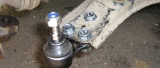
The intake and exhaust valves of automobile engines are poppet-shaped. The valve is opened by a valve mechanism controlled by an eccentric cam. The operation of the cam is synchronized with the position of the piston and the period of rotation of the crankshaft.
The valve guide is located coaxially with the valve seat so that a sealed gas-tight contact is ensured between the operating face of the valve and the seat. The valve operating chamfer and seat are beveled at an angle of 30° or 45°. These are the nominal chamfer angle values. Actual values may differ by one or two degrees from nominal values. The valves and valve seats used in most engines have a nominal bevel angle of 45°. The valve is pressed against the seat under the action of a spring. The spring is held on the valve stem (some auto mechanics call it the valve stem) by a spring support plate, which, in turn, is locked on the valve stem by a lock (cottons). To dismantle the valve, it is necessary to compress the spring and remove the crackers. After this, you can remove the spring, cuff, and remove the valve from the head.
Extensive testing has shown that there are optimal relationships between the various valve geometries. For engines with cylinder bores ranging from 3 to 8 inches (80 to 200 mm) bore, the optimal intake valve head diameter is approximately 45% of the cylinder bore diameter. The optimal exhaust valve head diameter is approximately 38% of the cylinder internal diameter. The inlet valve must be larger in size than the outlet valve to allow the same mass of gas to pass through. The larger inlet valve controls the low-velocity flow of rarefied gas. At the same time, the exhaust valve controls the high-speed flow of compressed gas. A smaller valve can handle this flow. As a result, the diameter of the exhaust valve head is approximately 85% of the diameter of the intake valve head. To function properly, the valve head diameter should be approximately 115% of the valve port diameter. The valve must be large enough to cover the window. The valve lift above the seat is approximately 25% of the head diameter.
The structure of both options
If you exaggerate, the collector is 4 pipes that connect into one. That is, a kind of “pants”, only with four “trouser legs”. It should be noted that there are also “two - three” or even “six” pipes. This device is determined by the number of cylinders in the engine, as we know on the OKA car there were only two cylinders (two pipes), for example, on the new FORD there are options with three (three pipes), and on some executive cars there are six cylinders (six pipes). Moreover, these will be both the intake and exhaust manifolds.
Here is just the top point, where one of their outputs will differ:
Intake - connects to the air or fuel supply system, so at the “top point” there will be either a carburetor or a throttle valve.
Exhaust - connects to the muffler and removes exhaust gases. Nowadays it is often connected to the catalyst.
Now in more detail about each type.
The exhaust manifold is the first element of the exhaust system
Let's begin a detailed study of the exhaust system, and first of all, consider the exhaust manifold.
This element is the first to take the blow from the hot exhaust gases escaping from the cylinders.
What is the exhaust manifold for and how is it designed?
As we have already said, the exhaust manifold is the first part of the car's exhaust system and is directly connected to the engine.
At first glance, it may seem that its role is quite simple - to collect what remains of the fuel from the combustion chambers of the engine cylinders and transmit it further through the system.
But if you delve deeper into the issue, it turns out that the parameters of the power unit - power and torque - also depend on the exhaust manifold.
Structurally, the element is very simple. It consists of several pipes (one for each cylinder), which are connected to the engine at one end and converge into one large pipe at the other.
You will not find any other parts in the exhaust manifold.
It is made from heat-resistant alloys, such as cast iron or special steel. In rare cases, even from ceramics.
The fact is that the conditions faced by the exhaust manifold cannot be called friendly - the temperature of the assembly due to hot gases can reach 900 - 1300 degrees. Real hell.
Therefore, there is an opinion that the element can burn out, but in reality this almost never happens - in fact, this part of the exhaust system can be called eternal.
Engineering variations on the theme of reservoirs
Despite its simplicity, the exhaust manifold has varieties, the appearance of which is due to the physics of gas circulation through pipes.
Because of this, developers have to make compromises, and we will definitely talk about them. But first, the varieties.
The following types of collectors are found:
- solid;
- tubular.
In the first case, the design turns out to be very cheap.
Its main feature is short outlet pipes and a common collection chamber. To be honest, one-piece manifolds are extremely ineffective for exhaust gas removal.
This is due to short tubes, due to which the influence of gas pulses on neighboring cylinders is great.
As a result, we have unsatisfactory purging of the combustion chambers, and this is reflected in many factors, including engine parameters.
In order for the engine to operate at maximum efficiency, tubular exhaust systems were developed.
They are the ones most often found under the hoods of modern cars.
They are exhaust pipes coming from the cylinders and converging into one (or sometimes first into several, and then into one).
When developing them, engineers have a lot to tinker with, since the engine output at different speeds depends on the length of the exhaust pipes and their diameter.
So, for example, if we take short tubes, then, thanks to the resonance effect, they will best ventilate the combustion chambers at high speeds.
But then the mutual influence of the cylinders on each other will increase.
Long exhaust pipes, in turn, are good at low speeds.
The story is similar with the diameter - a small pipe diameter is optimal from the point of view of the speed of gas removal at low and medium speeds.
But they experience a lot of resistance at high speeds, which is why the engine power drops. With larger diameter exhaust pipes the opposite is true.
Thus, engineers have to maneuver and look for compromises, which we mentioned earlier for good reason.
About tuning instead of an epilogue...
When thinking about the exhaust manifold, one cannot ignore the topic of tuning, because this part quite often ends up on the list of those subject to modification.
As a rule, on the market you can find different configurations of this element for a specific model.
Exhaust manifolds allow you to achieve, for example, good performance at low speeds or in the mid-range - for every taste and color.
And in motorsports, they often do away with exhaust manifolds altogether, connecting the exhaust pipes directly to each cylinder.
I hope, dear readers, we have delved deep enough into the study of the exhaust manifold. In future publications we will continue to study the structure of the exhaust system of cars, don’t miss it!
An exhaust manifold
So, the second contender, it also plays an important role - removing burnt gases. After the intake valves have been closed, the fuel is compressed and ignited by the spark plug - a mini explosion occurs, the pistons go down - the exhaust valves open and the burnt gases are removed.
It’s just that after the valves they must go into the muffler, and they are collected from each cylinder by the exhaust manifold (also one pipe per cylinder). It is also connected by its wide part to the head of the block, only (if we exaggerate) on the other side, then through the pipes the gases are collected into one large one, as a rule, first there is a catalyst that burns the gases, then after it there is a muffler (there may also be an outlet for turbine ). After this, the gases go further into the environment. It is worth mentioning that this tract extinguishes not only exhaust gases, but also the exhaust sound! More precisely, not he himself, but the muffler to which he transmits “working off”.
As you understand, the exhaust manifold operates at high temperatures, because the exhaust can often heat up to 950 degrees Celsius. Therefore, it is imperative to use metals, and not simple ones, but refractory ones capable of withstanding high levels of “heat”.
A sensor is often screwed into this outlet manifold, this is a “lamba umbrella” or an oxygen sensor; it “monitors” the content of oxygen and other gases in the exhaust.
Thanks to this sensor, the supply of the fuel mixture through our “supply” manifold is adjusted, that is, a relationship is obtained.
The exhaust tract, usually very durable in cars, lasts almost the entire life of the car.