Cost of repairing an engine with damaged valves
An engine with damaged valves requires serious repairs. The minimum cost of repairs for damaged valves is 10 thousand rubles and depends on the type of engine and how many valves were damaged.
Damage to engine valves can lead to various additional damage to engine components. The process of a timing belt breaking, leading to damage to the valves, can lead to catastrophic consequences for the engine. In some cases, it will require a complete replacement, which can amount to up to 50% of the cost of the car.
How to determine for yourself that the timing valve has burnt out
This is an engine part and at the same time the outermost link of the gas distribution mechanism. The valve group includes: a spring, a guide sleeve, a seat, and a spring fastening mechanism. All these parts operate under difficult mechanical and thermal conditions, experiencing enormous loads.
The seat-valve interface is subject to the greatest impact of high temperatures and shock loads. In addition, parts are constantly lacking lubrication due to high operating speeds. This causes them to wear out intensively.
Requirements for the group:
Valve group
The final link of the gas distribution mechanism is the valve group, which includes a valve, a spring, valve and spring mounting parts, a guide bushing and a valve seat.
The valve group operates under high mechanical and thermal loads. The valve-seat interface is the most loaded. These parts are subject to the greatest impact when seating the valve and operate at high temperatures.
The “valve-seat-guide sleeve” interface operates with insufficient lubrication and high valve movement speed, which causes intensive wear.
Based on the conditions in which the parts of this timing group operate, the following requirements are imposed on the valve group:
- hermetically sealed valves;
- low resistance to the working mixture and exhaust gases during intake and exhaust (good streamlining);
- minimum weight of parts;
- high strength and rigidity;
- high thermal resistance;
- effective heat removal from the valve (especially for exhaust);
- high wear resistance (especially in the “sleeve-valve” interface);
- high corrosion resistance in the seat-valve interface.
Valves
The valves open and close the intake and exhaust ports in the cylinder head. The main elements of the valve: head 12 and rod 9 (Fig. 1). The valve head is sometimes called the valve disc. The smooth transition from the head to the rod reduces the resistance to the flow of gases as they flow through the gas exchange holes. Since exhaust gases are removed through the exhaust valve at significant pressure, the head of this valve is usually made of a smaller diameter than the head of the intake valve. The temperature of the exhaust valve head of gasoline engines reaches 800...900 ˚С, and in diesel engines - 500...700 ˚С. The temperature load on the intake valve heads is much lower, however, it leads to heating of the valve disc up to 300 ˚C.
Therefore, for the manufacture of exhaust valves, heat-resistant alloys and materials are used, which are usually heat-resistant steels with a high content of alloying additives. In order to save expensive heat-resistant materials, exhaust valves are made of two parts. In this case, heat-resistant material is used for the head, and carbon steel is used for the rod. The head and the rod in this case are connected to each other by butt welding.
To increase corrosion resistance and reduce wear in exhaust valves, the working surfaces of the chamfer, and in some cases the surface of the head on the cylinder side, are surfaced with a layer of hard alloy 1.5...2.5 mm thick (Fig. 1).
Engine valve
The wide variety of materials from which internal combustion engine valves are made can present a difficult choice. This article will talk about valve production technologies, in what cases to use certain valves, their advantages and disadvantages, lightening and tulip grooves, and we will also talk about protective coatings and methods of applying them. This information is provided to help you make an informed decision when upgrading your valvetrain.
1.Valve production technologies.
When manufacturing exhaust valves, special attention is paid to manufacturing methods and materials that can withstand high temperatures for a long time and at the same time maintain strength. The requirements for the intake ones are not so stringent since they have additional cooling with a fresh air-fuel mixture. Many alloys meet the required properties if certain technologies are followed, but something always has to be sacrificed, and the weight of the part turns out to be large. A lot of research is being carried out and the identification of new materials does not stand still. Many patented technologies have not yet found their application in practice.
I won’t describe all the many technologies and their shortcomings in detail; let’s briefly go through the main ones. How to make a valve disc:
End rolling - a hot valve rod protrudes from the matrix and a pausson rotating at an angle to the axis of the matrix rolls out the rod in a circle, which is gradually fed into the matrix until it is given the required shape. A directional microstructure of the metal is created, parallel to the profile of the valve disc, which increases strength.
1-end of the workpiece. 2-matrix. 3-pause. 4-ready valve disc. 5-rod.
In the next method, the workpiece is fed into the matrix and the valve plate is rolled out in a similar way, while the stem is also squeezed into the hole, which also gives a directional microstructure similar to wood fibers. There are several other methods similar to those described.
The valve is made of steel grades : 40Kh9S2, 40XH, 40Kh10S2M, 20KhN4FA, 55Kh20G9AN4, 45Kh14N-14V2M, titanium alloys PT-3V, VT3, VT-14, VT6, with much lower temperature resistance (only intake valves) VT18U and VT25U and others with floats . Valves made of alloys based on the TiAl intermetallic compound have a comparatively low metal density and, accordingly, lower weight with greater hardness and heat resistance, even in comparison with conventional titanium-based alloys. But difficulties arise in manufacturing using conventional technologies that allow adding strength due to low ductility. In this case, they are made by casting , but in this case, porosity is formed in the metal structure, which is removed only by high-temperature gas isostatication, a very expensive procedure that accounts for the cost of the valve.
A combined system is widely used, when the rod is made of low-alloy alloys with greater hardness, and the plate is made of heat-resistant ones. The finished parts are subsequently welded using various methods or pressed on; the design is considered not very reliable.
Another manufacturing option, the valve stem and end are made of the same alloy; as a result of deformation and heat treatment, different metal microstructures are created, high hardness and creep resistance are ensured in the head; high heat resistance is provided in the plate. Again, manufacturing technologies are very expensive. I will not describe the other methods, which each have 3-4 transition zones in microstructure and annealing technology; they are all fundamentally similar to those described above.
Hot stamping into the end - a hot rod is simply pressed into a matrix in which the metal is distributed haphazardly, disrupting the microstructure, the simplest and most cost-effective method, which does not have the necessary strength.
Types of valves
There are only two widely used types of poppet valves: “ Tulip ” and “ T-shaped ”.
It is worth understanding the disadvantages and advantages to make your choice. And so the most common is the tulip, it has a large margin of safety, a streamlined shape, and often a lot of weight.
The T-shaped one is designed to a greater extent for a tuned engine that operates mainly at high speeds. It has a minimum radius of transition from the stem to the plate, light weight, which reduces the load on the gas distribution mechanism, extending service life, shifts the threshold of valve hanging, which allows the use of standard valve springs without resorting to reinforced ones, which take their share of the power, less wear on guide bushings, better purging. We'll talk about reliability a little lower.
Tulip valve relief
For economic reasons, many people strive to lighten the valves themselves; the purchase of new T-shaped valves costs a tidy sum, usually these are titanium-based valves that have low weight, minimal metal consumption and better strength and heat resistance characteristics, however, due to the labor-intensive production of such parts, the cost is very high.
I already said above that Tulip initially has a large margin of safety and there is an opportunity to lighten it at the cost of reliability and the unjustified risk of getting into yet another capital investment. Few people are stopped by this fact and the search begins for those who have already tried and do exactly the same, respecting the size of the opponent. You can find a lot of positive experience on this topic on the Internet; less often you come across a sad outcome of revision.
Now let's figure out why this happens. At the beginning, I described valve production technologies and materials. If you read carefully, you already realized that production technology and the microstructure created in the metal are of great importance, even as a result of heat treatment or the stamping method. When lightening the valve, part of the metal in the surface layers of which contained the main strength of the entire part is mechanically removed. The thermal stress of the plate increases as a result of which the valve material is not able to withstand the load and is susceptible to deformation. Some manufacturers apply special coatings with expanding properties; I will describe them in more detail at the end of the topic. From this we can conclude that the probability of the plate breaking is 50/50, because you do not know the technology and materials and you will act based on the experience of others or by eye. Add the possibility of a manufacturing defect and possible detonation, and you get this result.
However, this does not always happen and judging by the experience of a few, lightweight valves last 100 thousand and continue to work properly. If you still decide to get relief, think about cooling the plate; replacing the valve seats with bronze ones will help with this. It is through the seats that most of the temperature is removed. I already wrote about this in the topic Valve seat . Avoid sharp edges and thin edges on the plate, these places will be extremely overheated, increasing the likelihood of detonation and leading to burnout and destruction of the valve. There is absolutely no need for chamfers; make a smooth transition and round the edge of the plate. Do not forget to lap the valve to the seat, preferably not with diamond pastes. Consider options for lightening the remaining moving parts - spring plates, rocker arms or pushers.
Of course, preference should be given to factory T-shaped valves, without ignoring the brand; their reliability will not make you doubt. Don't even think about trying something made in China, even if it's titanium.
Protective coatings, application methods.
Three methods of coating metals have become widespread: plasma-powder surfacing, laser alloying, and surfacing with high-frequency currents. The coating of a completely different metal on the exhaust valve expands the protective properties of the part and the ability to withstand an aggressive environment. This allows the valve to be made from more suitable materials in terms of heat resistance and strength, without resorting to searching for a middle ground. This results in a durable and lightweight valve that is not able to withstand oxidation and wear, but the use of a thin layer of special coating will solve this problem.
High-temperature exhaust gases cause great damage to the valve, causing gas corrosion by water vapor, oxidation by oxygen, carbon monoxide, and sulfur oxide, which are formed as a result of combustion. The mechanical impact unravels the working chamfer, its size increases, the tightness is broken, which leads to the breakthrough of hot gases into the gap and greater burnout.
Next, I’ll tell you about the coating application methods, and we’ll get to know each of them in more detail.
Plasma-powder surfacing -
the most universal method, granulated metal powder is fed along with gas into the plasmatron. This method allows you to apply a high-quality coating with a thickness of 0.5-5.0 mm, the solubility of the metal of the part in the deposited layer is only 5%, a possible deviation from the nominal thickness is 0.5 mm, minimal oxidation of the deposited layer due to the gas supplied to the plasmatron, minimal heat-affected zone.
Laser alloying-
The part is exposed to a laser beam, heating the surface slightly above the melting point of the base. The temperature is controlled by laser power and beam diameter. As a result, active mixing of the alloying metal placed on the surface of the base with the metal of the part occurs to a depth of approximately 1-2 mm. This method makes it possible to apply coatings of stellite, a tungsten-chromium-cobalt alloy. The solubility of the base metal in the coating is 5-10%.
Surfacing with high frequency currents -
A ring made of deposited metal is installed on the valve plate, between the valve and the ring there is a powder flux or a gaseous medium (argon, nitrogen), under the action of a high frequency current the ring is heated and the valve plate is heated to the temperature of metal diffusion, the coating area is cooled with water on the other side of the valve, In this way, the deposited layer is frozen, while the valve rotates to ensure uniform heating. In this way, self-fluxing alloys EP616, EP616A, EP616B, EP616V are applied much cheaper than cobalt stellites and have sufficient hardness and corrosion resistance. The solubility of the base metal in the coating layer is 20-30%.
Titanium valve plate with chromium nitride (CrN) coating
An example with titanium nitride coating provides high hardness.
Resists carbon deposits and oxidation.
Why do you need to adjust valves?
Each engine cylinder has intake and exhaust valves. The former allow access to the air-fuel mixture in gasoline engines, or air in diesel engines, after which they return to their original position and reliably seal the combustion chamber. The second ones open to release exhaust gases - at the moment of injection they also fit tightly to the “seat” of the block head.
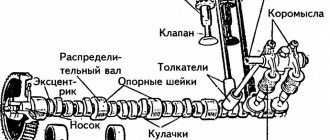
The timely opening of the valve is carried out by the camshaft, which pushes the rod at the right moment, pushing it out of the “seat”. It comes back with a spring. There is a pusher between the rod and the camshaft cam itself. And it is the gap between this pusher and the cam that is adjusted.
What does timely valve adjustment give? Ensures normal engine operation when hot, when the metal expands. The clearances affect the operation of the valves - they must ensure a tight fit when the engine is hot. They are called thermal gaps, and amount to tenths of a millimeter.
Valve adjustment is necessary to ensure that the engine provides the required power and lasts a long time.
How do engine valves work?
The valve that allows the mixture of air and fuel into the cylinder is called the intake valve. The valve through which exhaust gases leave the engine is called the exhaust valve. For the engine to operate efficiently at any speed, these valves must open at certain times.
This process is carried out by pear-shaped parts (cams) that are attached to the camshaft, which rotates under the action of a chain, belt or set of gears.
The camshaft may be located at the top of the block. In this case, small metal cylinders (pushers) are located above each shaft cam. When the end of the pushrod rests on the rocker arm, the cam acts on the valve stem, which is held in the raised (closed) position by a strong spring.
Overhead camshaft engine
In this design, a shaft located at the top of the engine is controlled by an internally toothed belt, and the contours of the cams interact directly with the tappets located above the valves.
When the tappet presses on the cam, it engages a rocker arm, which weakens the spring and opens the valve. With further rotation of the circuit, the spring returns to its original position and the valve closes. This design is typical for an engine with overhead valves in the cylinder head.
Some engines have no pushrods and use dual or single camshafts to open and close the valves.
This design is called an engine with a single camshaft and valves in the head. It has fewer moving parts, so it is more powerful and can operate at high speeds. In any case, there is a gap between the parts so that the valve can open and close freely as they expand when heated.
Clearances between the valve stem and the rocker arm or cam are essential for proper operation of the system, and their absence can cause serious damage to components.
If the clearance is too large, the valves will open too early and close too late, reducing engine power and increasing engine noise.
If the gap is small, the valves will not close normally, which will lead to weakening of compression.
In some engines, the clearances are adjusted automatically under lubricant pressure.
Camshaft with pushers
With a design in which the camshaft is located in the cylinder block, long pushrods act on rocker arms that open the valves. Engines with overhead valves in the cylinder head are considered less efficient than engines with a single camshaft and valves in the head, because the large number of moving parts limits the speed at which the engine can safely operate.
In an overhead camshaft engine with rods, the crankshaft is located in the cylinder head.
As the shaft rotates, each valve is opened using a pusher, rod and rocker arm. The valve is held closed by a spring.
The number of teeth on the drive chain sprocket is twice the number of teeth on the camshaft gear, so the shaft rotates twice as slowly as the engine.
Engine with single camshaft and valves in the head
In some models, the cams directly act on short levers called pins.
An engine with a single camshaft and valves in the head contains fewer parts to control the valves. The cams interact directly with pushrods or short levers (fingers), which in turn open and close the valves.
Such a system has less weight and technical complexity, because it lacks pushrods and rocker arms.
To control the camshaft using a sprocket on the crankshaft, a long chain is often used, which sometimes becomes slack. This problem is solved by adding intermediate sprockets and several short chains with high tension.
In addition, non-stretchable rubber oil-resistant belts with teeth can be used that engage the sprockets on the camshaft and crankshaft.
How often are adjustments made?
Of course, valve adjustment is done when a certain mileage has accumulated, but it is also different for different cars. This information can be found in the instructions. But experienced car enthusiasts advise visiting a service station after every 20-45 thousand kilometers for domestic cars, and 60-100 thousand for foreign cars.
But if you know how valve clearance affects engine performance, you will be able to identify problems yourself in time. If, when the hood is open, the engine makes noise, as if there is a sewing machine, then you need to urgently go to a service station. The second sign is a drop in power - the car does not “pull” as before. In such a situation, you don’t have to wait until the car has covered the allotted mileage; you need to take action as quickly as possible.
The adjustment work itself is very inexpensive and takes about an hour - you have to wait until the engine cools down.
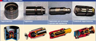
On some cars, adjustment is not made at all - if special hydraulic compensators are used. They themselves provide optimal conditions, and they may only need to be replaced, but this is rare. Hydraulic compensators can be installed on most cars, and you can forget about such adjustments forever.
Typical intake valve failures
Of course, the most common failure of valves is their bending as a result of a broken timing belt. The same thing can happen without a break if the belt was replaced by a non-professional who mistakenly placed marks on the crankshaft and camshaft (or camshafts) pulleys. Breaks are especially dangerous for modern complex engines equipped with variable valve timing and other high-tech systems.
Another common malfunction of the valve mechanism is the overgrowing of the intake and exhaust valves with carbon deposits. As a rule, the problem can be identified at a fairly early stage by a decrease in power and popping noises in the intake and exhaust pipes, a metallic knock in the cylinder head and a drop in engine power.
Number of valves in the engine
When it comes to valves, many people ask the question: “how many valves should an engine have?” There is no definite answer; a clear quantity can only be determined by studying the design features of the motor. Considering that in a four-stroke power plant the valve performs the intake and exhaust strokes, this means the minimum number per cylinder is two, one intake and one exhaust.
Modern power plants most often use a design with four valves (two intake and two exhaust) per cylinder. When the valve opens, the fuel mixture is thrown into the resulting hole, or exhaust gases escape. The larger the hole, the more efficient filling or cleaning will be. Accordingly, the efficiency of the motor will also increase.
It is impossible to enlarge the hole by enlarging the valve plate, since its size is limited by the size of the combustion chamber. Therefore, to improve the quality of mixture formation, a larger number of valves are installed per cylinder.
There are schemes in which two, three, and even five valves per cylinder are used. Considering that the filling process is more important for engine operation, the number of intake valves in odd-numbered patterns is always greater.
Valve mechanism design
A conventional engine requires a minimum of two valves per cylinder to operate. One inlet and one outlet. The valve itself consists of a rod and a plate (head). I call the place where the plate comes into contact with the cylinder head the saddle. Intake valves have a larger poppet diameter than exhaust valves. This ensures better filling of the combustion chamber with the air-fuel mixture.
Valve mechanism design
The entire valve mechanism consists of the following main elements:
Cams on the camshaft press on the valves. Their return to their original position is ensured by a spring. The spring is attached to the rod using crackers and a spring plate. To dampen resonant vibrations, not one, but two springs with versatile winding can be installed on the rod.
Valve guides
The guide bushing is a cylindrical part. It reduces friction and ensures smooth and correct movement of the rod. During operation, these parts are also subject to stress and temperature. Therefore, wear-resistant and heat-resistant alloys are used for its manufacture. The exhaust and intake valve bushings are slightly different from each other due to the difference in loads.