What is
Modern cars have an electric engine starting system. It is also often called a starter starting system. Simultaneously with the rotation of the crankshaft, the timing, ignition and fuel supply systems are switched on. The air-fuel mixture is burned in the combustion chambers and the pistons rotate the crankshaft. After reaching a certain crankshaft speed, the engine begins to work independently, by inertia.
To start the engine, you need to reach a certain crankshaft speed. This value differs for different types of engines. For a gasoline engine, the minimum required is 40-70 rpm, for a diesel engine - 100-200 rpm.
At the initial stage of the automotive industry, a mechanical starting system using a crank was actively used. It was unreliable and inconvenient. Now such solutions have been abandoned in favor of an electric starting system.
How does engine starting work?
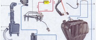
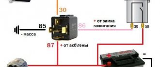
After turning the ignition key to the “start” position, the electrical circuit is closed. The current through the positive circuit from the battery is supplied to the winding of the starter traction relay. Then the current passes through the field winding to the positive brush, then through the armature winding to the negative brush. This is how the traction relay works. The movable core retracts and closes the power pins. When the core moves, the fork extends, which pushes the drive mechanism (Bendix).
After the power nickels are closed, starting current is supplied from the battery through the positive wire to the stator, brushes and rotor (armature) of the starter. A magnetic field appears around the windings, which sets the armature in motion. In this way, the electrical energy from the battery is converted into mechanical energy.
As already mentioned, the fork, during the movement of the retractor relay, pushes the bendix towards the flywheel crown. This is how engagement occurs. The armature rotates and drives the flywheel, which transmits this movement to the crankshaft. After starting the engine, the flywheel spins up to high speeds. To avoid damaging the starter, the Bendix overrunning clutch is engaged. At a certain frequency, the bendix rotates independently of the armature.
After starting the engine and turning off the ignition from the “start” position, the bendix returns to its original position, and the engine runs independently.
Electric starter
Electric car starter. Starter relay (top left, black). Traction relay (solenoid, in the top center, small diameter, golden color). The silver case contains a lever transmission and an overrunning clutch. The electric motor is large in diameter, golden in color.
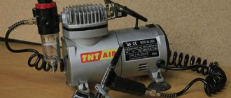
The most convenient way. When starting, the engine is spun by a brushed electric motor - a DC machine powered by a battery (after starting, the battery is recharged by a generator driven by the main engine). At low temperatures, commonly used acid batteries lose capacity (mainly due to an increase in the viscosity of the electrolyte; the electromotive force of the battery also decreases), and the viscosity of the oil in the lubrication system increases. Therefore, starting the engine in winter is difficult and sometimes impossible. If there is an electrical network, in this case it is possible to start from a network starting device (virtually unlimited power).
Electric motors of automobile starters have a special design with four brushes, which allows increasing the rotor current and the power of the electric motor.
On diesel locomotives with direct current electric transmission, the starter is a traction generator. The same scheme was used on some scooters (“Tula”, “Tourist”, “Tulitsa”, “Ant”), where the starter function is performed by a direct current generator mounted directly on the crankshaft (in the USSR such a system was called a “dynamo starter”, and later - “dynastarter”)
Operating principle of an electric starter
When the starter is turned on, electric current (through the start relay, otherwise the contacts in the ignition switch will burn out) is supplied to the traction relay (solenoid). The solenoid core retracts and, through a linkage, engages the starter motor gear with the ring gear (large gear) of the flywheel. After this, the starter relay contacts close. A very large current (tens and even hundreds of amperes) passes through this relay to the electric motor. After starting, the freewheel (Bendix) allows the engine flywheel and starter motor to rotate independently of each other. After turning off the starter, the starter parts return to their original state. On old cars (for example, GAZ-69, GAZ-63) there was no traction relay (solenoid), the driver turned on the starter with a pedal on the floor of the cab.
On cars with automatic transmissions there is a holding winding that does not allow the solenoid core to move, if the automatic transmission selector is installed in the running positions “D”, “R”, “L” or “2”, a switch is installed in the automatic transmission that supplies current to the holding winding . The engine can only be started in the “P” (park) and “N” (neutral) positions.
The magnitude of the electrical voltage at the starter
On cars with gasoline internal combustion engines, the on-board voltage is 12 volts, and the same electrical voltage is used at the starter. A number of cars produced in the first half of the 20th century used 6 volts.
On cars with powerful diesel engines, the on-board voltage is 24 volts. This is due to the fact that a diesel engine with a large displacement and a high compression ratio requires a powerful electric starter. Two 12-volt car batteries are installed, connected in series.
With equal electrical power, when the electrical voltage doubles, the current strength is correspondingly reduced by half: P=I⋅U{\displaystyle P=I\cdot U}, where I{\displaystyle I} is the current strength, and U{\ displaystyle U} — voltage.
Increasing the voltage allows you to reduce the discharge current of the battery, as well as reduce unnecessary heating of the wires.
Passenger cars, vans and light trucks with diesel engines use 12-volt starters (this is quite enough).
On old trucks with diesel engines (YAZ-200, YAZ-210), the on-board voltage was 12 volts, and the starters were designed for 24 volts. There were two 12-volt car batteries connected in parallel; when started, they switched to a serial connection. All 12-volt electrical consumers were powered by a single battery at startup.
Features of battery operation
Successful engine starting will depend on the condition and power of the battery. Many people know that such indicators as capacity and cold cranking current are important for batteries. These parameters are indicated on the marking, for example, 60/450A. Capacity is measured in Amp-hours. The battery has low internal resistance, so it can deliver large currents for a short time, several times its capacity. The specified cold cranking current is 450A, but subject to certain conditions: +18C° for no more than 10 seconds.
However, the current supplied to the starter will still be less than the specified values, since the resistance of the starter itself and the power wires is not taken into account. This current is called inrush current.
Reference. The internal resistance of the battery is on average 2-9 mOhm. The starter resistance of a gasoline engine is on average 20-30 mOhm. As you can see, for proper operation it is necessary that the resistance of the starter and wires be several times higher than the resistance of the battery, otherwise the internal voltage of the battery during startup will drop below 7-9 volts, and this should not be allowed. When current is applied, the voltage of a working battery drops to an average of 10.8V for a few seconds, and then recovers again to 12V or slightly higher.
The battery supplies starting current to the starter for 5-10 seconds. Then you need to pause for 5-10 seconds for the battery to “gain strength”.
If, after attempting to start, the voltage in the on-board network drops sharply or the starter cranks halfway, this indicates a deep discharge of the battery. If the starter makes characteristic clicks, then the battery is completely dead. Other reasons may include a broken starter.
MEMO FOR STUDENTS LEARNING TO DRIVE A CAR.
You must come to driving lessons in clothes and shoes that do not restrict movement. Sports style clothing and shoes are most preferred.
THE STUDENT IS RESPONSIBLE TO KNOW: - traffic rules and skillfully apply their requirements in practical driving lessons;
— safety measures during practical lessons on driving and vehicle maintenance and carry them out;
— rules and techniques for driving, content and objectives of the exercise.
1. SAFETY: - listen carefully and strictly follow the instructions of the instructor, do not argue or argue with him during classes! — start the engine only with the permission of the driving instructor; — before starting the engine, make sure that the gearshift lever is in neutral, the car is locked in place with the handbrake, and there is no one nearby; — carefully monitor the readings of instrumentation; — use the controls smoothly, without much effort or jerking, without weakening your monitoring of the road; — while moving, keep a distance of at least 25-30 meters, at stops and parking lots - 5 meters, maximum speed 40-50 km/h; — overtake or bypass a stationary vehicle only with the permission of the driver; — control the situation around the car using the rear-view mirrors; — when passing oncoming traffic and when passing pedestrian crossings, exercise special caution and attentiveness; — do not allow sudden braking, acceleration, or turning; — on a slippery road, brake by reducing engine speed and, if necessary, pressing the brake pedal repeatedly (stepped or intermittent braking) without disengaging the clutch, excluding wheel locking; — if the car skids, turn the steering wheel in the direction of the skid; — stop the car smoothly, in a predetermined place.
2. SCOPE AND SEQUENCE OF WORK DURING CONTROL INSPECTION BEFORE DEPARTURE: Check and eliminate detected faults: - cleanliness of the car, glass, mirrors and license plates; — level of coolant, engine oil, brake fluid, fuel. Are there any drips? — adjust the position of the driver’s seat, the tilt of the seat back; — adjust the rear view mirrors; — fasten your seat belt;
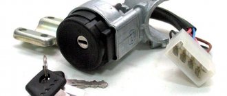
3. PROCEDURE FOR STARTING THE ENGINE: — make sure that the parking brake is on; — set the gearshift lever to neutral position; — press the clutch pedal all the way and hold it (disengage the clutch), turn on the ignition by turning the ignition key clockwise 45 degrees; - turn on the starter by turning the key another 45 degrees, holding it in this position for 1-2 seconds until the engine starts (the sound of the engine running will be heard), then release the key (turn off the starter); — once again make sure that the gearshift lever is in the neutral position and smoothly release the clutch pedal; - The engine is turned off by turning the key 45 degrees counterclockwise (turning off the ignition).
4. FEATURES OF STARTING THE ENGINE IN WINTER: — in winter, at low temperatures, before starting the engine, you must turn on the high beam headlights for a few seconds (about 5) to warm up the battery; — turn on the ignition and only turn on the starter for half a second. In principle, it is enough just to “click” the starter. Next you need to wait three to four seconds. By starting the engine in two (or three) steps, you will make it easier to start a cold engine and save the battery; — in the cold season, it is undesirable to put the car on the parking (hand) brake for long-term storage, in order to avoid freezing of the brake linings to the brake drum; — at low temperatures, a special liquid is poured into the washer reservoir, according to the ambient temperature conditions.
5. ALGORITHM FOR PUSHING AWAY: — look around, including in the rear-view mirrors; - fully depress the clutch pedal (disengage the clutch) smoothly and quickly and pause for 2-3 seconds; — engage first gear; — turn on the turn signal; - set the engine speed at 1,500 - 2,000 to ensure smooth starting by pressing the gas pedal; — release the parking brake lever; — look in the rearview mirrors; — smoothly release the clutch pedal (the gas pedal is held in one position), when the car starts moving, hold your foot on the clutch pedal (1-2 seconds), then continue to smoothly release the clutch pedal while simultaneously smoothly pressing the gas pedal.
Current strength at start
Starters for gasoline and diesel engines will differ in power. For gasoline internal combustion engines, starters with a power of 0.8-1.4 kW are used, for diesel engines - 2 kW and higher. What does it mean? This means that a starter with a diesel engine needs more power to rotate the crankshaft into compression. A 1 kW starter consumes 80A, a 2 kW starter consumes 160A. Most of the energy is spent on the initial rotation of the crankshaft.
The average starting current for a gasoline engine is 255A for successful cranking, but this takes into account a positive temperature of 18C° or higher. At sub-zero temperatures, the starter needs to turn the crankshaft in thickened oil, which increases resistance.
Features of starting the engine in winter conditions
In winter it can be difficult to start the engine. The oil thickens, which means it is more difficult to turn it. The battery also fails frequently.
At sub-zero temperatures, the internal resistance of the battery increases, the battery drains faster, and is also reluctant to deliver the required starting current. To successfully start the engine in winter, the battery must be fully charged and not frozen. Additionally, you need to monitor the contacts on the terminals.
Here are some tips to help start your engine in winter:
Thousands of drivers start their engines every day and go on business. Getting started is possible thanks to the coordinated operation of the engine starting system. Knowing its structure, you can not only start the engine in a variety of conditions, but also select the necessary components in accordance with the requirements specifically for your car.
Source
Procedure for starting a car engine indoors
The answer to this question is clear: you can’t. Maybe this is the only case? No. As practice shows, such bans are often perceived by motorists as something seasonal.
Many of them believe that the threat of poisoning from exhaust fumes is only relevant in the summer. And they are mistaken. In winter, indeed, the specific gravity of air (in an unheated garage) is greater than in summer, and this helps to “dilute” harmful gases, that is, to slightly reduce their concentration.
However, we must not forget that in winter the carburetors are adjusted to a richer mixture at idle, as a result of which the content of harmful gases in the exhaust, and therefore their concentration in the room, increases. Fatal poisoning from exhaust gases occurs much more often in winter than in summer, since prolonged idling of engines is often used to heat the cabin or interior, and finally, simply to warm up the engine. Exhaust gases enter the cabin through leaks in the body (especially in older cars). They are often helped by fan draft, wind, and tightly closed windows. Some amateur designers from car enthusiasts go even further. The editors introduced us to letters from the magazine's readers proposing to improve the winter heating of the Cossacks' cabin in a simple and "effective" way, as they consider it.
It is only necessary, according to the authors of these proposals, to embed a fan into the wall of the engine compartment, which would pump warm air from there. This is a sure way to cause poisoning from exhaust gases, the concentration of which in the warm air of the engine compartment is quite high. It is clear that motorists are not yet sufficiently aware of the toxicity of exhaust gases. Let us briefly recall why car exhaust is dangerous. The exhaust gases of internal combustion engines contain more than a hundred substances harmful to human health, primarily carbon monoxide and various hydrocarbons. nitrogen oxides. When using leaded gasoline, toxic lead compounds are added. The current maximum standards for the content of toxic components in exhaust gases in our country ensure the safety of the driver and passengers only if the exhaust is directed into the atmosphere and the car is technically sound, in particular, the exhaust pipe and all connections of the exhaust system are sufficiently sealed. Interpretation of dreams - dream book: interpretation of dreams. Dream: meaning and interpretation.
Carbon monoxide poisoning is especially dangerous
Engine starting systems
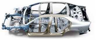
The starting system ensures the initial cranking of the crankshaft when starting the engine, since the engine itself does not create torque when stationary, and will not start without an external power source.
In order to breathe life into the engine, its crankshaft must be given a certain initial (starting) rotation speed, after which gas exchange and thermodynamic processes in the cylinders begin to occur, as well as the functioning of the main systems that ensure the operation of the engine - power, ignition, lubrication. A combustible mixture begins to flow into the engine cylinders (for diesel engines - clean air), at the right moment a spark-forming electrical impulse is supplied to the spark plugs, or a portion of fuel is injected (for diesel engines), and the lubrication system ensures a reduction in friction forces during the operation of engine mechanisms - the engine starts and starts working on its own.
In what condition must the car be left for the autostart to work?
Autostart is quite capricious and its performance directly depends on whether the driver did everything correctly when leaving the car. Owners of cars with a manual transmission will have to leave the gear selector in neutral. Otherwise it won't start. Owners of cars with automatic transmissions must leave the car in park mode.
Since there is a high probability of driver error (when he does not put the speed switch in the neutral position), many developers equip their devices with a “soft neutral”, a device thanks to which the engine cannot be turned off until the speed switch is in the neutral position. This option reduces the likelihood of error. There is another option when autostart simply cannot be turned on if the speed switch is in the wrong position.
Source
1. Engine starting system design
In a conventional engine starting system, three main mechanisms can be distinguished:
Let's look at how the brush holder works: the brush holder combines 4 brushes that are pressed against the commutator. Two of the four brushes are in insulated mandrels and connected to the armature windings and then through the commutator to the field windings. Both are grounded to the housing.
Engine starting system diagram:
Starting system drive system
This mechanism transmits torque from the electric motor to the flywheel. A drive gear is installed on the armature shaft. The action of the electromagnetic switch causes the drive lever to engage the drive gear with the toothed rim of the flywheel (in this position, rotation is transmitted to the engine shaft). When the engine is started, the window clutch disengages and the drive gear now rotates to idle. Later, when the ignition is turned on, the drive gear disengages from the toothed rim.
Now let's look at the real mechanism: the window clutch transmits rotation in only one direction and is connected to the drive gear. The starter motor coupling has screw splines. There are also screw splines on the armature shaft. The drive gear is able to slide along them while rotating. Helical splines ensure smooth engagement of the drive gear with the toothed rim. After the toothed rim engages with the drive gear, the engine spins up. The drive gear rotates the toothed rim (while the window clutch operates). When the engine is running, the engine rotates the drive gear, while the window clutch is disengaged. The drive gear rotates at idle so as not to damage the electric motor.
Electromagnetic switch
Electromagnetic switch - causes the drive arm to move the drive gear and directs current to the electric motor.
Diagram of operation of the electromagnetic switch
There is a plunger in the center of the switch. The plunger performs two functions: it moves an actuator arm connected to one end of the plunger, and also actuates the main contacts through a contact plate connected to its other end. The plunger is surrounded by a retractor winding, which pulls the plunger to the main contacts. On top of the retractor winding there is a holding winding that holds the plunger against the contacts. When you turn the ignition key, an electric current passes through the retractor and retainer windings, creating a magnetic field. This field moves the plunger to the right. As a result, the contact plate closes the main contacts. Now terminal 30 is connected to terminal C connected to the motor. A powerful current is supplied to the starting electric motor, at the same time, the drive lever engages the drive gear and it begins to spin the engine.
Starter device
The car starter is an electric motor. It converts electrical energy from the battery into mechanical work, which drives the flywheel and crankshaft to begin the process of moving the pistons. All engines are equipped with a starter.
The principle of operation of the device is based on the laws of physics, which are known from school. If you place a wire frame with two ends between the two poles of a magnet and then pass a current through it, it will begin to rotate. This is the simplest electric motor.
A simple car starter consists of a metal case containing four magnetic cores (shoes). These magnets in the housing constitute the stator of the electric motor . Previously, an excitation winding was wound on the shoes, to which electric current was supplied from the battery. That is, it was a classical electromagnet. Modern devices use conventional magnets.
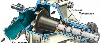
Another important part of the device is the anchor . It is a shaft with a pressed core made of electrical steel. In the grooves of the core there are the very frames that will rotate around the poles of the magnet. The ends of the frames are connected to a commutator, to which four brushes fit - two positive from the battery and two negative, which will go to ground.
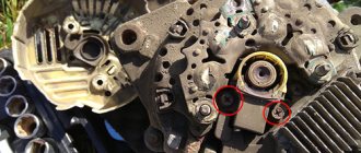
The closing rear cover contains brush holders with springs that constantly press the brushes towards the commutator to ensure contact. Also installed in the rear cover is an armature support sleeve or bearing.
There is an input contact on the metal case. The positive terminal of the battery (+) is connected to this contact. The current passes through the armature frames and exits to the negative mass brushes. Ground is connected to the negative terminal of the battery. Thus, a magnetic field is created around the armature frame and it rotates.
The positive battery wire that goes to the starter is much thicker than the others. This wire carries a starting current of approximately 400A.
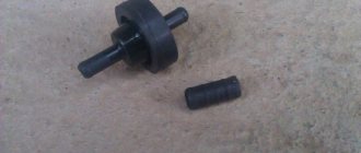
Current from the battery to the starter cannot be supplied continuously. It is only needed when the engine starts. Therefore, between the positive wire of the battery and the starter contact there is a so-called copper penny that closes the contacts.
There is also a spline connection on the armature shaft, on which there is a guide bushing and a bendix with a gear with the possibility of axial movement. This movement ensures that the gear contacts directly with the flywheel ring gear. In simple words, we can say that Bendix approaches the flywheel, turns it as much as necessary, and then moves back.
But the bendix does not move along the shaft on its own. This is done by another smaller electromagnet - solenoid relay . A fork fits from the relay to the gear, which pushes the bendix. The retractor coil is supplied with control current from the battery through the ignition switch. When the ignition is turned on, the coil is magnetized and retracts the core. This core, on the one hand, is connected to the Bendix fork, on the other, to the nickels that close the contacts of the electric motor. When the voltage from the solenoid relay coil is removed, the plug is pulled back into place and the electric motor stops working.
The armature begins to rotate only when the gear has already engaged with the flywheel.
Main components
Thus, the main components of the starter can be called:
Engine starting system
The engine starting system is designed to start the car engine. It ensures that the engine rotates at the speed at which it starts. On modern cars, the starter engine starting system is most widespread. We will talk about what components the car engine starting system consists of in this article.
Car starter
Automotive internal combustion engines require starting assistance.
Engine starting systems consist of the following components:
The starter itself must meet the following technical requirements:
Starter design features
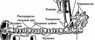
To create the required fuel-air mixture for spark-ignition engines and automatic ignition temperature for diesel engines, the starter must rotate the internal combustion engine crankshaft at a certain minimum speed. Engine speed is highly dependent on engine type, displacement, number of cylinders, compression ratio, friction losses, additional loads generated by engine operation, fuel management system, type of oil used and ambient temperature.
In general, starting torque and starting speed with decreasing temperature require a gradual increase in starting power. However, the power generated by the starting battery decreases with decreasing temperature, as its internal resistance increases. This conflicting relationship between electrical load requirements and available power means that the worst operating condition for an internal combustion engine starting system is a cold start.
Due to the large current consumed by the starter, the voltage drop on the supply wires significantly affects the characteristics of the starter.
Classification of engine starting systems
The automatic engine starting system has a rated power of up to 2.5 kW at a rated voltage of 12 V. It can start spark-ignition engines with a displacement of up to 7 liters and diesel engines with a displacement of up to 3 liters.
Starters can be classified according to the following criteria, according to their technical types:
Modern cars mainly use permanently excited starters with pre-engagement with a gearbox. They combine high starting power with compact dimensions.
Starter design and operation
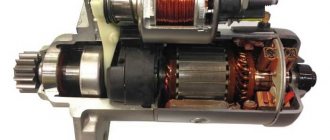
The starter (Fig. “ Starter with gearbox ”) essentially consists of an electric motor, a drive mechanism and, starting with a power of about 1 kW, a gearbox.
When starting, the starter gear engages the flywheel via a traction relay. The starter is connected to the drive gear either directly or through a gearbox that reduces the speed of the electric motor. The gear rotates the crankshaft of the internal combustion engine through the flywheel ring gear until the internal combustion engine begins to operate stably. Once the engine is started, it can quickly accelerate to high speeds. After just a few ignitions, the engine accelerates so powerfully that the starter is no longer able to match its speed. The internal combustion engine “overtakes” the starter and, as a result, can accelerate the armature to extremely high speeds if the freewheel between the gear and the armature does not cancel the unwanted blocking. As soon as the driver releases the ignition key, the traction relay is de-energized and the buffer spring disengages the drive gear from the flywheel ring gear using a spiral groove.
Starter motor
The starter motor is a conventional DC motor. Electric motors with 6 poles predominate. Magnetic materials available today have made it possible to develop starters that are resistant to demagnetization and have a highly efficient magnetic flux that provides greater starting power. Since the magnetic field is created by a permanent magnet, and the reverse effect of the armature magnetic field is very small, the excitation is practically constant throughout the entire operating range.
Starter gearbox
The standard is a plastic ring gear made from fiber reinforced polyamide. Depending on requirements, a steel ring gear with additional shock-absorbing elements can also be used.
Types of starter drives
The starter drive ensures the engagement of the starter gear with the ring gear of the internal combustion engine flywheel. The drive consists of a gear, a freewheel, a buffer spring and a traction relay.
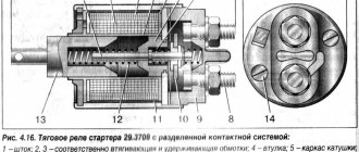
Starter traction relay
The traction relay used in the starter (Fig. “ Traction relay ”) consists of a housing, an armature, a magnetic core, a contact carrier (a plate with contacts, a contact spring), a retractor and retaining winding, a return spring and a cover with built-in contacts. The traction relay performs two functions:
In order for the relay armature to ensure movement of the gear along the entire stroke length, a current of about 30 A is required to create the necessary magnetic force.
When the relay armature is fully retracted (the air gap is zero), then significantly less magnetic excitation and, therefore, less relay current (about 8 A) is required to hold the armature in the extreme position.
The winding is divided into retracting and holding parts, primarily to limit the heating of the winding. These two parts of the winding are connected in parallel (Fig. Traction relay circuit "), which means the addition of the magnetic excitation of the two windings.
The beginning of both windings is connected to contact 50 of the traction relay. The end of the retractor winding is connected through the starter armature, and the end of the holding winding is connected directly to zero potential. When voltage is applied to contact 50 of the traction relay (the ignition is on), the armature is pulled into the housing by the magnetic force created by the retracting and holding windings. This movement pushes the gear through the drive lever forward towards the flywheel. Only when the relay armature is almost completely pulled inward will the contact bridge close and the main starter current turn on. This prevents the starter from rotating until the starter gear engages the flywheel ring gear. Since the two ends of the pull-in winding are now connected to the positive side, current flows only to the holding winding. The lower magnetic force of the holding winding is sufficient to reliably hold the relay armature until the ignition switch opens.
Kinds
According to the design, starters are:
Without gearbox
A gearbox is an intermediate mechanism whose main task is to reduce rotational forces. In such models, the crankshaft has direct engagement with the gear. Ignition occurs faster, almost instantly, due to direct contact. Among the advantages of this design is its simplicity. An additional gearbox is integrated into the structure and in the event of a breakdown, it will need to be disassembled.
Gearless starters can be easily repaired with ordinary hand tools. Due to its strong simplicity, the connection and repair diagrams are elementary. But the main disadvantage of models without a gearbox is instability. During severe frosts, they may fail and may not start the engine the first time.
With gearbox
The main difference from the previous version is the presence of a planetary gearbox. Many experts recommend geared models, as they have one distinct advantage - the ability to start a car even with a very low battery. Low electricity consumption is greatly enhanced by permanent magnets, which improve performance.
In addition, this combination solves problems with the winding that can lead to starter failure. The only drawback is the possible breakage of the gear during prolonged use. If the starter was made with a defect, which is not uncommon, their service life is greatly limited.
Device
The design and principle of operation of the starter are simple. The engine starting system directly depends on the flywheel. This is a mechanical element that, when turned, causes the motor to produce energy. And to start the engine from the battery, an intermediate unit is required.
The operating principle of a standard car starter is determined by the operation of the following elements:
- Anchor. This is an axle made of alloy steel. It rotates on a plain bearing. The core is pressed onto it and collector plates are installed. Its structure involves grooves into which the winding is placed.
- Brushes. These are graphite conductors that perform a simple function - transmitting electricity to the collector plates. This allows you to increase the overall starter power.
- Relay. Transfers voltage to the winding and pushes out the overrunning clutch.
- Electric motor. Consists of several cores with a winding. The rotor can be mounted on plain bearings or conventional bushings. The second option is considered the worst, since they tend to wear out with active use. As a result, such equipment breaks down faster.
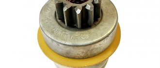
- Bendix. Element for transmitting torque and rotation to the crankshaft.
The operation of the starter is often determined by this set of elements, but there may be additions. A number of models have a special button that allows you to start the car even without a key.
More details about the starter design in the video
Turning on the starter
In a traditional start, the driver connects battery voltage (ignition key in start position) to the starter relay. The relay current (about 30 A for cars, about 70 A for trucks) creates a certain power in the relay. It pushes the starter gear against the flywheel ring gear and activates the primary starter current (200-1000 A for cars, about 2000 A for trucks).
The starter is turned off when the ignition switch is opened, interrupting the voltage supply to the starter relay.