Some time ago, I noticed that the clutch began to slip and literally a week after that the loaf almost stopped moving, it started with great difficulty, and did not accelerate beyond 70. And then I decided to change the clutch. No sooner said than done.
On Saturday morning I quickly removed the universal joints, rods, etc. First I removed the steering gear, then the gearbox,
I went to the store and bought a new Weber disk.
The next day, Sunday, I started putting it back together and installed the clutch (it’s not difficult - the kit included a thing for centering the disc). I brought together the Republic of Kazakhstan and the checkpoint. The book said check how the gears are engaged after assembly, but I didn’t do this, and as it turned out, it was in vain.
Then he began to install the gearbox and control valve in place. I lifted the gearbox and the steering wheel using belts with ratchets that secure the load; the rest is impossible to describe.
It turned out that the recipe for installing a gearbox is simple - “you climb under the car, curse loudly for three hours and the gearbox is in place.” I screwed on the gearbox and supports, and that was the end of Sunday.
Then during the week I collected the rest, filled in the oil and everything seemed to be...
Changed gears - everything was fine. I started the engine - the gears did not shift... and the downshift did not shift... The next day, I replaced the fluid in the clutch system, adjusted the free play of the clutch pedal. After this, the gears began to engage with the engine turned on. “Well, finally, everything is fine,” I thought. I threw all my things into the back and started driving. And then it turned out that the loaf only moves in low gear, neutral is not switched on in the RK.
The next day (it was Saturday again), in the evening, I quickly removed the steering gear and it turned out that when I was assembling the steering gear and gearbox, the gear for engaging direct and low gear fell out of the fork... I adjusted the fork, turned on the direct gear on the steering gear, then the gear was pressed with the fork and did not dangle. And he began to install the RK in place. It took about 3 hours, I couldn’t get the shift rod into the hole in the bracket for a long time, I had to unscrew the support. Before installation, I changed the gasket and applied sealant. After 3 hours the RK was installed. The rest is just trifles. On Saturday night we managed to start moving. Replacing the clutch took more than a week... (our motto is “dementia and courage”)
The clutch serves to briefly disconnect the engine shaft from the gearbox when changing gears and smoothly attach it when moving away.
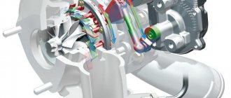
UAZ loaf cars or officially UAZ-452 are equipped by the manufacturer with a dry mechanism with one disk. This device has a torsional vibration damper.
The device ensures the transmission of torque from the power unit to the transmission with a force of 17 kg/cm.
Design
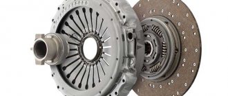
The main components of the clutch of the UAZ-452 car:
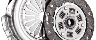
- driven disk assembly with friction linings;
- a pressure disk or basket assembled with a casing;
- release levers.
The stamped steel casing is attached to the engine flywheel with six centering bolts. It is made with three windows, where the projections of the cast iron pressure plate fit.
Six steel springs are installed between the pressure plate (basket) and the casing.
Their compression force ensures the transmission of torque from the flywheel further through the casing, pressure plate to the driven disc. In order to prevent heat transfer from the springs, washers made of heat-insulating material are installed on the pressure plate side.
Modern cars are equipped with a hydraulic drive instead of a mechanical drive . The fluid creates increased pressure, making it much easier for the driver to control the pedal.
everything useful is here
Removing the clutch pressure and driven discs SEQUENCE OF ACTIONS
We remove the gearbox.
Removing the hydraulic clutch slave cylinder
Using a 12mm wrench, unscrew the four bolts securing the lower part of the clutch housing. One of the bolts secures the end of the ground wire to the clutch housing.
Remove the lower part of the clutch housing with the gasket.
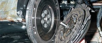
We use a chisel to mark the relative positions of the flywheel and the clutch drive plate (“basket”).
While holding the flywheel from turning with a screwdriver or a mounting spatula, use a 12mm wrench to evenly unscrew the six bolts securing the “basket” to the flywheel. Only two “basket” mounting bolts are accessible at a time. To access the remaining bolts of the flywheel, turn it, engaging the teeth of the ring with a screwdriver.
We remove the “basket” and the driven disk.
The driven disk hub protrudes more on one side than on the other. This side should be facing the gearbox. We install the driven and driving disks on the flywheel and secure them with bolts. We do not tighten the bolts to maintain the mobility of the driven disk.
Clutch functions
By pressing the pedal, the driver acts on the fluid in the line. The fluid transfers pressure from the master cylinder piston to the slave cylinder piston. The working cylinder moves the shutdown fork with its rod.
Together with it, the release bearing is pressed, transmitting force to the clutch mechanism, which disconnects the transmission from the power unit.
By releasing the pedal, the driver returns the entire mechanism to its original state. Under the influence of the return springs, all parts involved in the process of squeezing the clutch take their normal position.
Device
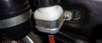
The clutch master cylinder (MCC) is a hydraulic cylinder that converts the force from the driver's foot into the pressure of the working fluid in the clutch control drive circuit.
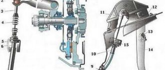
Clutch master cylinder: 1, 4 — cuffs; 2 - piston; 3 - plate; 5 — main cylinder body; 6 - spring; 7 - cover; 8 — mesh filter (or reflector); 9 — master cylinder reservoir; 10 - fitting; 11 - eye; 12 — lock nut; 13 — pusher of the working cylinder; 14 — cover; 15 — thrust washer; 16 — retaining ring; 17 — thrust ring; 18 — valve cage; 19 - valve; 20 — main cylinder fitting; 21 – fitting; 22 – gasket; A - compensation hole; B - bypass hole
Carrying out replacement
Step-by-step replacement instructions:
- Place the UAZ loaf car on high supports made of bricks and wooden blocks. Avoid falling from supports.
- Drain the operating oil from the gearbox and gearbox.
- Unscrew the rear driveshaft from the drive shaft. Place tags. When reassembling, install exactly the same as it was. Otherwise vibrations will appear.
- For the convenience of further work, unscrew the rear cardan completely - from the rear axle too. Place tags. Unscrew the front driveshaft only from the drive shaft. Place tags.
- Remove the muffler.
UAZ clutch master cylinder: operating procedure, repair, device, worker, engine
So, I was driving home after the mushrooms and suddenly there was an incomprehensible crunching sound and the clutch died, it became very soft and incomprehensible, just like that. Having slowed down on the side of the road, I inspected the pedals as best I could and did not find any springs on the clutch pedal. Having decided that it was just a spring, I moved on. However, the clutch began to work absolutely disgustingly, but nothing, the gears somehow engaged, it was possible to move. Having hobbled home the next day, I started repairing, deciding at the same time to do some tuning ^_^. Namely, to replace the standard UAZ GCS with the Zhiguli one. (As it seemed to me then, it was all the fault of the cylinder, because it had worked poorly before, did not hold the clutch depressed, and gradually released) The following were purchased: 1. GCS from the classics (VAZ 2101-07 ATE 1101.3 -760 rub.) 2. A pair of bolts with nuts and washers 3. Clutch master cylinder tube VAZ 2101-07 - 19 rubles (threads are different for UAZ and Zhiga)
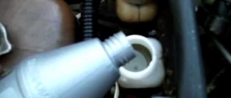
Getting to the clutch master cylinder in a loaf is not easy
View of the cylinder under the torpedo
New cylinder with bolts
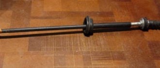
Old, with the stem already removed
Tube threads, standard UAZ at the top, Zhiguli at the bottom
Next, just like everyone else, holes were drilled in the pedal block in the buzubra
We also had to drill holes in the cylinder itself so that everything would fit, because drilling the block itself was already dangerous
Frequent malfunctions and their causes
The clutch system of a UAZ vehicle is characterized by various malfunctions: the clutch is strengthened, the mechanism does not disengage, slips or does not pump. Timely maintenance, replacement of worn parts, lubrication and monitoring of the liquid level in the tank, diagnostics of all systems and components of the mechanism help to avoid such problems.
The operating instructions provide basic information about the operation of transport units, their preparation for operation, the rules and frequency of monitoring the functionality of the units, the main malfunctions and the decoding of error codes. Following the manufacturer's recommendations will extend the life of the equipment. Simple breakdowns can be fixed yourself.
For more complex system malfunctions, it is recommended to contact a service center.
The first category of reasons relates to the problem when the system cannot start completely when the pedal is lowered. The algorithm of actions is as follows:
- Lack of free play on the pedal. Repair measures consist of adjusting the shutdown drive.
- A malfunction in the pressure plate movement design requires replacement of the part or removal of the cause of the jam.
- Defective pressure springs, reduced force. Purchasing new spare parts will help correct the situation.
- Oil getting on the friction surface of the discs. It is necessary to rinse and wipe the elements dry with gasoline.
- Prolonged slippage causes overheating. The mechanism will cool down on its own after some time.
Malfunctions
The main malfunctions of the GTZ are damage to the cuffs. If the “fungus” is damaged, the piston will not create pressure in the system and the clutch will stop squeezing. Usually these are burrs, cracks, or simply worn down. Frequent, repeated pressing will, of course, help, but not for long. It is impossible to turn on the speed and move away. It is necessary to change the cuffs or replace the entire main one.
In the second option, if the second annular cuff malfunctions, the liquid will leak out. DOT will drip onto the cab floor. It is quite possible to replace it with a ring from the repair kit.
Repair
The presence of a diagram of the internal structure of the structure allows you to carry out independent repairs in case of simple malfunctions. Increased fuel and oil consumption, coolant leakage, uncharacteristic noises and knocking in the mechanism are the first indications for repair. Maintenance and replacement of worn-out components helps prolong the functioning of parts and vehicles.
How to adjust the clutch pads
In order to adjust the clutch on a UAZ, you will need to carry out the following repair work:
- Measuring with a ruler the free radius of movement of the drive pedal that turns off the mechanism. The standard value for the spring-lever type should be within the range of 35 to 55 mm, for the diaphragm type - from 5 to 30 mm.
- Measuring the full travel of the pedal after it has been lowered to the limit. The standard value for the spring-lever type is 18.5 cm, for the diaphragm type - 16.5 cm.
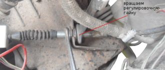
- Adjust the required position by changing the position using the key.
- Controlling the distance when the pedal is lowered between the partition of the motor part and the middle of the rod axis. It is necessary to achieve a value of 9.6 cm. The fork must have a free path of movement of at least 1.7 cm. Changing the length of the work basket pusher is an adjustment tool. To do this, you need to remove and screw back the pusher until the desired value is obtained.
Adjustment of the free play of the clutch pedal is required if the distance between the rotating part located on the release levers and the adjusting screws and elements of the device does not lie within the range of 50.75-52.25 mm. The screws can be removed and put back in until the correct size is established.
The diaphragm spring connection does not require free play adjustment and does not require adjustment of the mechanism release system. The correct dimensions of the gaps and strokes are ensured by the design features.
How to bleed the clutch
Bleeding the hydraulic drive will be required if the pedal is pressed too softly and it is not possible to completely turn off the mechanism. All this indicates the presence of air in the hydraulic drive unit. Repair measures are carried out through the bypass valve in the same way as work with a hydraulic brake drive. Having an assistant will make the task easier. Sequencing:
- Adding working fluid to the master cylinder tank to the standard limit.
- Release the bypass valve head from the protective element, connect the rubber hose.
- Preparing a container with a volume of more than 0.5 liters filled with the working mixture. Place the free end of the hose into the liquid.
- Creating pressure in the resulting system with several presses on the pedal in 1-2 seconds.
- Turn the bypass valve half a turn.
UAZ clutch device.
From the book by E.N. Orlova and E.R. Varchenko "UAZ Cars" maintenance and repair
UAZ clutch device
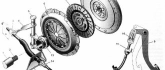
Fig.81. Clutch 1 - pull lever pin; 2 — pull lever; 3 - finger; 4 — pull-off lever roller; 5 — pull lever fork; 6 - thrust bolt; 7 — clutch release spring; 8 — clutch release; 9 — clutch release bearing; 10 — pressure spring; 11 — clutch casing; 12 — heat-insulating washer; 13 — lower part of the clutch housing; 14 - flywheel; 15 — driven disk; 16 — pressure disk; 17 — front bearing of the gearbox input shaft; 18 - crankshaft; 19 — gearbox input shaft; 20 — needle bearing; 21 — clutch housing
The clutch (Fig. 81) of UAZ vehicles is single-plate, dry, and consists of a pressure plate 16 with a casing, clutch release levers 2, support forks 5 and pressure springs 10 and a driven disk 15 with friction linings and a torsional vibration damper. Characteristics of pressure springs are given in table. 8. Table 8
| Spring catalog number | Loaded spring length, mm | Spring designation | Spring load, N | Spring color |
| 51-1601115 | 40 | A, B | 760…790, 790…820 | Red, Brown |
Fig.82. Clutch driven disc 1 - friction linings; 2 - rivets; 3 — driven disk spring; 4 — damper plate; 5 — damper spring; 6 — hub; 7 — friction rings; 8 — adjusting rings; 9 — driven disk; 10 — persistent finger; 11 — balancing weight;
The driven clutch disc (Fig. 82) has two friction linings 1, riveted to the disc independently of one another through leaf springs 3, and is connected to the damper plate 4 using pins 10. Cylindrical damper springs are located simultaneously in the windows of the hub flange, driven disk and damper plate. When transmitting torque from the friction linings to the hub, the springs are compressed and ensure smooth transmission of torque from the engine to the transmission. The rotation of the friction linings with discs relative to the hub is limited by the pins resting on the edges of the U-shaped cutouts made in the hub flange. The friction vibration damper of the driven disk consists of two friction washers installed on both sides of the hub flange and adjusting rings. The outer diameter of the friction lining of the driven disk is 254 mm, the inner diameter is 150 mm, and the thickness of the lining is 3.5 mm. The dimension of the hub splines is 5.4 x 28.5 x 35, the number of splines is 10. The clutch is engaged using a fork mounted on the clutch housing, which moves the clutch with a thrust ball bearing. The bearing presses on the heads of the adjusting screws of the clutch release levers. The levers, turning on the axles, retract the pressure plate and disengage the clutch. After removing the force from the fork, the release springs retract the clutch with the bearing to its original position. The characteristics of the release springs are given in table. 9. Table 9
| Spring catalog number | Name | Loaded spring length, mm | Spring load, N |
| M-2472 | Pedal release spring | 160 | 140…160 |
| 11-7547 | Same thing, forks | 150 | 75…95 |
| 11-7562 | Same thing, couplings | 36 | 27.5 |
Fig.83. Hydraulic clutch release for utility vehicles: 1 - cover; 2 — pedal axis; 3 - fork; 4 and 12 — tension springs; 5 — clutch release pedal; 6 - coupling; 7 - spring; 8 — ball joint; 9 — clutch release fork; 10 - hydraulic hose; 11 - working cylinder; 13 and 18 — caps; 14 — bleeding valve; 15 - cuff; 16 - piston; 17 — pusher; 79 — lock nut; 20 — screw part of the pusher; 21 — master cylinder pusher; 22 — protective cap; 23 — outer cuff; 24 - piston; 25 — return spring; 26 - fitting; 27 — inner cuff; 28 — washer; 29 — compensation hole; 30 - bypass hole; 31 — clutch master cylinder; 32 — hydraulic tube; 33 - tank; 34 - mesh filter
The clutch release drive is hydraulic (Fig: 83 and 84). The drive consists of a suspended pedal, a master cylinder, a pipeline and a working cylinder. On wagon-type cars, the fuel tank is located under the instrument panel to improve access to it, and the instrument panel has an easily removable cover. On utility vehicles, the reservoir is installed directly on the master cylinder body. When you press the clutch pedal, the piston moves and the compensation hole 29 closes (see Fig. 83), after which the working fluid is forced out of the master cylinder and moves the piston and pusher of the working cylinder, transmitting the force from the pedal to the clutch release fork. When the clutch pedal is smoothly released, the pressure in the system drops and the displaced fluid returns to the master cylinder. When the pedal is abruptly released, the liquid forced out of the system into the main cylinder does not have time to fill the space vacated by the piston and a vacuum is created in the main cylinder in front of the piston head. Under its action, the liquid from the nutrient tank passes through the bypass hole in the piston head into the cavity in front of the piston head, pushing back the spring plate and compressing the edges of the sealing collar. Subsequently, this excess liquid is forced out through the compensation hole back into the nutrient tank. The spring constantly presses the piston to its rearmost position until it hits the washer.
There is a constant gap of 0.3...0.9 mm between the pusher head and the spherical cavity on the piston, which ensures guaranteed free play of the clutch pedal. The full travel “B” of the pedal, which ensures disengagement of the clutch, is 200 mm. For normal operation of the clutch, it is required that the gap between the bolt heads of the clutch release levers and the bearing be within 2.5...3.5 mm. This corresponds to a stroke of the outer end of the clutch release fork of 3.5…5.0 mm and a free stroke “A” of the clutch pedal within the range of 35…55 mm, measured along the pedal platform. The free play of the pedals is adjusted by changing the length of the working cylinder pusher Fig. 84. Clutch release drive for carriage-type vehicles: 1 - reservoir; 2 — clutch release; 3 — clutch release fork; 4 - pusher; 5 — tension spring; 6 - lock nut; 7 - working cylinder; 8 — bleeding valve; 9 - cap; 10 - hydraulic hose; 11 - pedal; 12 and 13 — hydraulic tubes; 14 - main cylinder up
Leveling up
After successful installation and assembly of the element, it is necessary to fill in new hydraulic fluid. The same one is used as for the brake system. After this, unscrew the air valve of the working cylinder several turns and press the clutch pedal 5-7 times. To avoid running to the salon several times, call an assistant who will bleed the system. Be careful - when you press the pedal, hydraulic fluid will flow out of the valve. Therefore, prepare the container first. This could be an ordinary mineral water bottle. To avoid leaks, use a rubber hose. Place one end on the air valve and lower the other end into the neck of the bottle. The liquid will splash at first - this is normal. With subsequent presses, the amount of air will decrease. Press the pedal until clean, bubble-free liquid comes out of the hose. This will mean that there is no more air left in the system. Screw the valve back on and put on the protective rubber cap. Due to its location, the part is constantly exposed to water, dirt and dust. To protect the valve from clogging, this rubber cap is provided. Check the level under the hood. If necessary, top up to the maximum level. During operation, maintain the level at maximum. At this stage, bleeding of the UAZ clutch slave cylinder is completed. The pedal will return to its factory stroke.
DIY replacement
First you need to drain the remaining liquid in the system. This can be done using a syringe. This operation is necessary to flush out dirt from the hydraulic drive system. On some models, access may be blocked by the cooling system expansion tank. For convenience, remove the container’s fastening nuts and remove the hose. It should be unscrewed with a 10mm wrench. Next, we dismantle the metal tube that comes from the clutch master cylinder. It can be copper or aluminum. After this, we remove the main cylinder, having previously unscrewed the two fastening nuts with a 13mm wrench. Using a 17 socket, you need to remove the hose that comes from the working cylinder. Next, we will again need a 13mm wrench. Using it, we unscrew the two bolts that secure the clutch slave cylinder. The UAZ is in neutral gear. The working cylinder itself on this car is mounted on the gearbox housing. To avoid damaging other elements, carefully disconnect the pushrod from the fork. If the hoses are removed “in weight” (that is, on the removed element), the cylinder can be secured with an adjustable wrench on one side, and on the other, unscrew the tube with a cape. But be careful, as mechanical stress may cause the rubber to crack.
DIY repair
So, the part has been removed and is ready for disassembly. First, unscrew the air bleed valve and remove the retaining ring. After disassembling the part, we inspect the condition of all elements - spring, piston, pusher and sealing rubber bands. They must not show any signs of mechanical damage. Next, we wash the insides of the element. There is no need to do this with aggressive liquids like gasoline and diesel fuel. Fill a medical syringe with hydraulic fluid and use pressure to clean out the dirt inside it. If the damage is only local, we need a repair kit to restore it. It is worth noting that even with one damaged part, all the entire elements are replaced, be it an elastic band, boot or spring. This will increase the service life of the working cylinder.