The research and production company Ural Equipment offers production of crankshafts, quickly and inexpensively. We produce metal parts of any complexity and shape from any type of material. The main focus of the research and production company is shaft production. Unlike other similar organizations, we take on the most complex orders, which only real professionals can do.
Design and purpose of the crankshaft.
As a rule, the crankshaft consists of several metal elements (elbows), they are located on one main axis. The knees are of complex shape, with large protrusions. They are cast in one piece along with the shaft. The shaft elbows are necessary to fix the connecting rods on which the pistons are attached. On the shaft, in addition to the knee, there are also other elements - cylindrical support spacers (necks), they are located between the knees, making it possible to fix the shaft inside the cylinder block.
Or call 8-800-250-88-72. Delivery across Russia
A poorly fixed shaft cannot rotate quickly, so cylindrical support spacers are located along the entire length of the shaft, creating a good fulcrum. Support spacers allow the shaft to rotate inside the cylinder block. The support spacers also have special bearings, but they do not have rollers. Such bearings are called main bearings. The role of rollers and balls is performed by lubricant, which flows continuously into the area of the support spacers. The crankshaft is a complex metal part that must be made in strict technical proportions by a professional specialist and only using modern equipment. We have all this and much more, so order the production of crankshafts from the research and production company Ural Equipment.
During production, our specialists comply with the highest precision conditions, even to such a level that there is no minimum runout when starting the crankshaft.
During manufacturing, the crankshaft itself has special channels and voids through which oil flows to the connecting rod bearings. There are also closed plugs, which in turn serve to trap particles and dirt that may be in the filled oil.
Due to the voids and channels, the shaft rotates gently and slides smoothly at the fixation points, generously lubricating the motor with clean oil. When manufacturing shafts of any complexity , at the very front end (toe) of the crankshaft, using special milling equipment, keyways are cut out, which serve for attaching special sprockets, a drive pulley, as well as auxiliary elements of the timing drive.
On the other side of the crankshaft, using turning and milling equipment, our specialists grind a flange using a special technology, where a central hole is drilled in advance for the bearing; it will form the primary support for the gearbox shaft. The flange also has a threaded hole for fixing the flywheel.
At the back and front of the crankshaft there are sealing seals that prevent oil from leaking at the ends of the flywheel that come out of the cylinder block.
Material and methods for producing blanks for crankshafts
Crankshafts are made from carbon, chromium-manganese, chromium-nickel-molybdenum, and other steels, as well as from special high-strength cast irons.
The most widely used steel grades are 45, 45Х, 45Г2, 50Г, and for heavily loaded diesel crankshafts - 40ХНМА, 18ХНВА, etc. The advantage of steel shafts is the highest strength, the possibility of obtaining high hardness of journals by nitriding, cast iron shafts are cheaper. Medium-sized steel crankshaft blanks in large-scale and mass production are produced by forging in closed dies on hammers or presses, and the process of obtaining the blank goes through several operations. After preliminary and final forging of the crankshaft in dies, the flash is trimmed on a trimming press and hot straightened in a die under a hammer.
Due to the high requirements for the mechanical strength of the shaft, the location of the material fibers when receiving the workpiece is of great importance in order to avoid their cutting during subsequent machining. For this purpose, stamps with special bending grooves are used. After stamping, before machining, the shaft blanks are subjected to heat treatment - normalization - and then cleaned from scale by pickling or processing on a shot blasting machine.
Crankshaft castings are usually made from ductile iron modified with magnesium. Shafts produced by precision casting (in shell molds) have a number of advantages over “stamped” ones, including a high metal utilization rate and good damping of torsional vibrations, which often makes it possible to dispense with an external damper on the front toe of the shaft. In cast billets, a number of internal cavities can also be obtained during casting.
The allowance for machining journals of cast iron shafts is no more than 2.5 mm per side with deviations according to the 5-7th accuracy classes. Less stock fluctuation and less initial unbalance have a beneficial effect on the operation of tools and equipment, especially in automated production.
The straightening of the shafts is carried out after normalization in a hot state in a die on a press after removing the workpiece from the furnace without additional heating.
Oil holes in crankshafts usually connect adjacent main and connecting rod journals and are made by drilling. The holes in the cheeks are caulked or closed with plugs on the threads.
Large crankshafts such as marine crankshafts and tunnel crankcase engine crankshafts are dismountable and bolted together. Crankshafts can be installed not only on plain bearings, but also on roller bearings (connecting rod and main bearings) and ball bearings (main bearings in low-power engines). In these cases, higher demands are placed on both manufacturing accuracy and hardness. Such shafts are always made of steel.
Using the crankshaft.
The crankshaft can be used almost anywhere. Most often it is used in piston engines, as well as press units, pumps, compressors, crank mechanisms and other types of devices where a rotation mechanism is used.
The crankshaft is used in engines. The operation of an engine (car, etc.) cannot be imagined without a crankshaft. On each device, especially in car engines, the crankshaft is located differently. As a rule, its location depends on the number of working cylinders, the size and stroke length of the piston, and a host of other different parameters.
What is a crankshaft? Device, purpose, principle of operation
The crankshaft is one of the main elements of the engine. It is part of the crank mechanism. It has a complex structure. What is this mechanism? Let's consider.
Device and purpose
The crankshaft receives the forces from the piston and converts them into mechanical energy. This mechanism is affected by rotational forces. It works constantly under high load. Therefore, to prevent the part from failing prematurely, crankshafts are made of high-quality, high-strength cast iron alloys. Then all parts are hardened with high frequency current. There are shafts with double counterweight or no counterweight at all. The engine cam is located directly in the motor housing. As for the design, it generally depends on the engine.
Support mechanisms
So, knowing what the engine crankshaft is designed for and what forces act on it during operation, you can understand why the joints between the cheeks and the crankpins are slightly rounded. This helps prevent premature destruction. There is a connecting rod between the cheeks. Mechanics who service engines call it a “knee”. It is designed to ensure uniform ignition, so that engine operation is as balanced as possible, so that minimal torsional and bending forces act on the shaft. The crankshaft is a part that operates at high speeds. The rotation of the connecting rods and the shaft itself on supports is ensured by plain bearings. Thrust elements are installed on the extreme or middle main journal. The purpose of this bearing is to prevent axial displacement and movement of the mechanism.
Working of the crankshaft from the inside
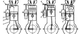
The operating principle is generally simple. When the piston is removed as far as possible, the crankshaft jaws and connecting rod are aligned. At this moment, fuel ignites in the combustion chambers and gases are released, which move the piston towards the crankshaft. The connecting rod also moves with the piston, the head of which turns the crankshaft. When the latter turns, the connecting rod journal moves upward and the piston moves with it.
Lubrication system
Lubrication plays an important role. The crankshaft is a rotating part, which means it will experience friction. A lubricant supply is provided from the common lubrication line to the journal supports. Then, through the channels in the cheeks, the oil will reach the connecting rod journals. Lubrication significantly increases the wear resistance of all shaft parts.
Malfunctions
Due to high loads, this mechanism fails. Among the typical malfunctions is accelerated wear of the journals. It is associated with problems in the cylinder block. Scratches on the surfaces of the journals also often occur. This happens due to poor circulation or lack of lubrication, or due to a violation of temperature conditions. Scratches on the surfaces of the necks can be seen especially often. It is necessary to distinguish between simply scratches and cracks that form due to metal fatigue. Beating and deflection of the part often occur. This is especially true for engines of high-speed cars.
How to make a replacement?
Of course, for some types of faults, you can get by with repairs - grinding or grooving. But sometimes it is not possible to restore the shaft. In this case, you can replace the old mechanism with a new one. By the way, this is the most expensive component in the engine. Especially in diesel power units. Before the crankshaft is replaced, axial play is checked. This will simplify the selection of axial liners. It is necessary to find the marks on the liner and the cylinder block. They indicate the direction in which the main bearing caps should be installed. All parts that interfere with dismantling the shaft must also be removed. In repair manuals, the dismantling process is described differently, since there are 8 and 16 valve engines, with an in-line or V-shaped cylinder arrangement. Then you need to install a new crankshaft in place of the old one - you must strictly follow the instructions of the car manufacturer and do not confuse the position of the crankshaft. Due to the high responsibility, all work must be carried out in a specialized service.
So, we have found out the structure, purpose and principle of operation of the car crankshaft.
Or from high-strength perlite cast iron:
- grade HF 45-0;
- grade HF 50-1.5;
- grade VCh60-2;
- grade VCh40-0;
- grade VCh40-6.
During the production process, the crankshaft must be subjected to thorough heat treatment with a hardness of up to 229-269 HB. To increase wear resistance during operation, all crankshafts are hardened at high temperatures by our engineers. The depth of the hardening layer is approximately 2-4 mm, the hardness of hardening with these parameters is about 52-62 HRC.
To make the shaft stronger for bending, when manufacturing crankshafts, due attention must be paid to the correct execution of the transition elements (fillets). To avoid rapid premature wear, to increase the fatigue strength of the part (crankshaft), it is necessary that a real specialist undertake the manufacturing. Such specialists work with us. The most popular, durable steel today is grade 42 HMFA steel. The service life of such a part is ten years. When manufacturing gear shafts, it is necessary not only to take into account all the technical parameters of the shaft, but also to strictly adhere to the chemical composition of the workpiece. To determine exactly what material (cast iron or steel) the shaft needs to be made from, you need to know the environment in which the part will be used and, based on these parameters, select the appropriate workpiece.
Material and manufacturing technology of crankshaft blanks
Material and manufacturing technology are often closely linked. In this case, steel shafts (in order to achieve the highest strength and toughness) are produced by forging, cast iron (the material cannot be forged) - by casting.
Steel crankshafts
Crankshafts are made from carbon, chromium-manganese, chromium-nickel-molybdenum and other steels, as well as from special high-strength cast irons. The most widely used steel grades are 45, 45Х, 45Г2, 50Г, and for heavily loaded diesel crankshafts - 40ХНМА, 18ХНВА, etc. The advantage of steel shafts is the highest strength, the possibility of obtaining high hardness of the journals by nitriding, cast iron shafts are cheaper [ source not specified 204 day
].
The choice of steel is determined by the surface hardness of the journals that needs to be obtained. A hardness of about 60 HRC (necessary for the use of roller bearings) can, as a rule, only be obtained by chemical-thermal treatment (cementation, nitriding, cyanidation). For these purposes, as a rule, low-carbon chromium-nickel or chromium-nickel-molybdenum steels (12ХН3А, 18ХНВА, 20ХНМА) are suitable, and for medium and large-sized shafts more alloying with expensive molybdenum is required. However, recently for this they began to use cheap steels of regulated hardenability, which make it possible to obtain high hardness while maintaining the viscosity of the core. Less hardness, sufficient for reliable operation of sliding bearings, can be obtained by high-frequency hardening of both medium-carbon steels and gray or high-strength cast iron (45..55 HRC) [ source not specified 204 days
].
Medium-sized steel crankshaft blanks in large-scale and mass production are produced by forging in closed dies on hammers or presses, and the process of obtaining the blank goes through several operations. After preliminary and final forging of the crankshaft in dies, the flash is trimmed on a trimming press and hot straightened in a die under a hammer [ source not specified 204 days
].
Due to the high requirements for the mechanical strength of the shaft, the location of the material fibers when receiving the workpiece is of great importance in order to avoid their cutting during subsequent machining. For this purpose, stamps with special bending grooves are used. After stamping, before machining, the shaft blanks are subjected to heat treatment - normalization - and then descaled by pickling or processing on a shot blasting machine [ source not specified 204 days
].
Large crankshafts such as marine crankshafts and tunnel crankcase engine crankshafts are dismountable and bolted together. Crankshafts can be installed not only on plain bearings, but also on roller bearings (connecting rod and main bearings), and ball bearings (main bearings in low-power engines). In these cases, higher demands are placed on both manufacturing accuracy and hardness. Therefore, such shafts are always made of steel [ source not specified 204 days
].
Cast iron crankshafts
Cast crankshafts are usually made from ductile iron modified with magnesium. Shafts produced by precision casting (in shell molds) have a number of advantages over “stamped” ones, including a high metal utilization rate and good damping of torsional vibrations, which often makes it possible to dispense with an external damper on the front toe of the shaft. In cast billets, a number of internal cavities can also be obtained during casting.
The allowance for machining journals of cast iron shafts is no more than 2.5 mm per side with deviations according to the 5-7th accuracy classes. Less stock fluctuation and less initial unbalance have a beneficial effect on the operation of tools and “equipment”, especially in automated production [ source not specified 204 days
].
The straightening of the shafts is carried out after normalization in a hot state in a die on a press after removing the workpiece from the furnace without additional heating.
Oil holes in crankshafts usually connect adjacent main and connecting rod journals and are made by drilling. The holes in the cheeks are caulked or closed with plugs on the threads.
High quality crankshafts.
For manufacturing, we use new forging technology, which helps us achieve high quality crankshafts. Today we have introduced another new production technology - casting from high-strength cast iron with the addition of modified magnesium and alloyed nickel-molybdenum cast iron.
For the casting method of manufacturing crankshafts, we use high-quality perlite cast iron grades 50-1.5 and HB 187-255. This type of shaft has a lot of good advantages over others (forged):
- lowest consumption of materials;
- reduction in the number of machining operations;
- the ability to give the required shape in relation to the fatigue strength of the material and the distribution of the metal.
Cast crankshafts, unlike forged ones, have the best ability to dampen the torsional vibration process. As for cast iron shafts, they have slightly less strength than forged ones, especially in bending.
That's why we use high-quality materials when manufacturing custom crankshafts from cast iron. Our specialists manufacture custom-made full-support shafts. The journals of shafts manufactured in our workshops have a high level of wear resistance, which allows customers to use bearings made of lead bronze.
The mass of the manufactured crankshaft is somewhere 8-15% less than the mass of the forged crankshaft. After crankshafts are manufactured, they undergo a hardening, annealing, and normalization procedure, where the internal stress in the shaft is relieved. All this is done in order to facilitate machining of the part and increase the quality level of the metal device.
Machining crankpins
The processing of connecting rod journals differs in the method of cutting in the milling head. According to the first scheme, cutting is made into the opening between the cheeks by an amount until the specified diameter of the neck is reached. And the subsequent removal of the allowance is carried out using a circular feed. According to the second scheme, cutting occurs directly into the neck, and the rest of it and the opening between the cheeks are processed using a circular feed. In this case, by reducing the plunge length, processing productivity increases. According to the first scheme, the shafts of twelve cylinder engines are processed simultaneously with two cutters from independent drives of sequential processing in a combination of the 1st-6th, 2nd-5th and 3rd-4th journals. The contours of the neck and cheeks are formed on separate machines. The necks and cheeks of the shafts of six- and eight-cylinder engines are processed according to the second scheme on one machine. The machine has independent positions with independent drives for processing two shafts simultaneously.
The main journals are milled at the same time, while maintaining the dimensions. The connecting rod journals are milled sequentially (1st, 2nd, 3rd and 4th) with the journal diameter and thickness of the cheek flanges on both sides, fillet radii, and crank radius maintained. The axes of the cranks of the 2nd, 3rd and 4th journals relative to the 1st journal are maintained with an accuracy of ±15′. Linear dimensions to the ends of the cheeks are maintained with an accuracy of 0.2 mm. The width of the necks and radii of the fillets according to the given dimensions are determined by the tool used. The shaft is supplied to round milling machines with machined shanks for mounting in the chuck beds and with a groove of diameter and width on the middle neck for installing a steady rest. When milling the main journals, the middle support is located in a rigid steady rest, and the 2nd and 4th journals are installed in a follower hydraulic steady rest. Thanks to this, the part has a reliable fastening and is not subject to deformation during processing. The allowance is removed in two sets, consisting of two and three cutters located on opposite sides of the part. This arrangement of the tool makes it possible to reduce the magnitude of the forces twisting the shaft during processing. When milling connecting rod journals, the 2nd, 3rd and 4th main journals are located in hydraulic rests, and the 1st and 5th journals are placed in the base liners of the clamping chucks. In the process of milling the connecting rod journal, the milling cutter performs a reciprocating movement in the horizontal plane, synchronous with the crank shaft. As can be seen from the above diagrams, the cutting forces are perceived by the shaft shanks, secured in the chucks of rigid spindles. Double shaft drive, rigid and precise rests mounted on the journals ensure minimal twisting and deflection of the shaft. Shaft deformation using the new technology is 0.1-0.2 mm (versus 1.5-2 mm using the old one). This made it possible to avoid the first re-centering and, after high-frequency quenching and tempering, obtain crankshafts with runout on the main journals in the range of 0.3-0.4 mm.
Thanks to the high precision achieved on circular milling machines, the grinding allowances for machined main and connecting rod journals are kept to a minimum. With this method, an envelope curve in the form of a polygon with a large number of edges is formed on the treated surface. This profile is the result of specific processing conditions with this tool. When examining the processing surface, it seems at first glance that subsequent final grinding can only be carried out with increased wear of the grinding wheel. However, in practice, the opposite picture occurs when the edges cause self-regulating wear and cleaning of the grinding wheel grains. This feature of the process allows in some cases to abandon the preliminary grinding operation. The milling heads are equipped with carbide turning plates, which are installed in precisely made grooves and secured with hardened wedges.
Depending on the profile, the blades have up to eight cutting edges. When rotating or replacing the plates, the accuracy of circular rotation and the width of the tool are maintained within the tolerance of the plates, which is according to GOST 19086-73. The material of the plates for processing shafts made of steel 50G-SSh and 60HFA is T14K8 hard alloy; plate shapes 07141—270660 according to GOST 19061—73, 09141—180600 according to GOST 19058—73, etc. Changing and checking the plates of the milling head is carried out outside the machine, therefore, when replacing a cutter, there is no need to set up the machine, which reduces the downtime of equipment associated with maintenance, and ensures consistent quality. Currently, the method of circular milling of crankshaft journals is the most progressive, as it provides high productivity and accuracy in obtaining the geometric parameters of the part, as well as reducing internal stresses in the metal fibers. The designs of machine tools for this type of processing are being improved. In particular, circular milling machines with an external tool arrangement are being replaced by machines where processing is carried out with a cutter with an internal tooth arrangement. The new processing principle allows, on the one hand, to create a more rigid working body of the milling head, which ensures quiet operation when the operating modes are increased by more than 2 times, on the other hand, the machine has become smaller in size. An example of such machines is mod. RFK-250, RFK400.
Or call 8-800-250-88-72. Delivery across Russia
When the process of machining (grinding) of crankshafts is completed, the next technological stage of manufacturing begins - heat treatment (tempering), which once again improves the technical characteristics of the part and increases its mechanical properties. As a rule, in our research and production company Ural Equipment, when manufacturing crankshafts, heat treatment is carried out several times, so we achieve the highest quality of metal products. Secondary processing of the part (thermal technology) is carried out by heating with current at a very high frequency.
Additional processing of metal parts.
In order to somehow alleviate the mechanical impact on steel (increasing the quality of the part) during the manufacturing process, we use a unique processing technology - reducing the hardness of the material due to the annealing procedure. The complete annealing procedure is that the part is heated to a very high temperature of 1000°C, and the material remains in this state for some time, and then cools to the required temperature (room temperature 23-25°C).
How are we different from the rest?
- In our production shops, we produce metal parts of any complexity, and also perform a number of different welding and assembly works, milling, turning, boring, metalworking, drilling.
- All finished products, if necessary and at the request of the customer, are additionally processed and painted, as well as tightly packaged and delivered to their destination.
- Our research and production company also provides individual services, which include all work cycles, from design (drawings) to delivery of finished products.
- We strive to develop our technologies every day. We are open to long-term and effective cooperation - and this once again indicates that we are ready to make compromises in order to offer you the most favorable terms of cooperation. For these and many other reasons, to manufacture crankshafts .